COMINOX Sterilclave 6 B Speedy User manual

SERVICE MANUAL
-Steam Sterilizer-
FOREWORD
This manual IS NOT an integral part of the sterilizer.
The manual is addressed to qualified, specialized technicians for routine maintenance
and repairs.
Technicians or operators must be authorised in writing by COMINOX.
Technicians must read this manual and follow the instructions herein contained. COMINOX
is not liable for any injury and/or damage to people or property or to the sterilizer itself
should the conditions herein illustrated be disregarded.
This manual contains industrial secrets which must not be disclosed. The manual and its
annexes must not be edited, modified, copied or given to third parties unless authorised
by COMINOX.

2

3
CONTENTS
CONTENTS........................................................................................................................................ 3
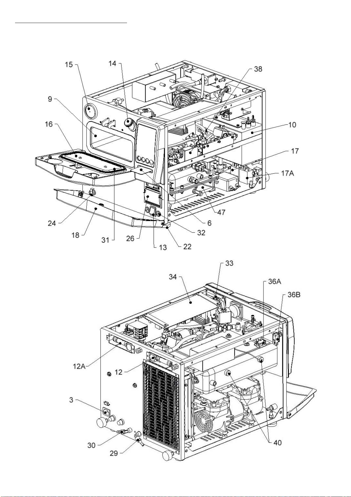
Reference list .................................................................................................................................... 5
Graphical reference representation Mod. 6 B SPEEDY............................................................. 6
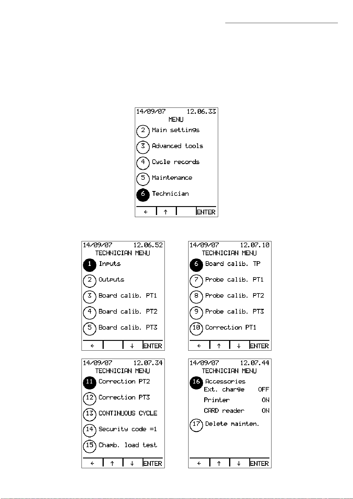
TECHNICIAN MENU ......................................................................................................................... 9
Inputs ............................................................................................................................................... 10
Outputs............................................................................................................................................ 11
PT1 / PT2 / PT3 board calibration ................................................................................................ 12
Temperature selector ................................................................................................................... 12
TP board calibration...................................................................................................................... 16
PT1 / PT2 / PT3 probe calibration ................................................................................................ 18
PT1 / PT2 / PT3 correction ............................................................................................................. 18
Continuous cycle........................................................................................................................... 19
Security code ................................................................................................................................. 19
Accessories ..................................................................................................................................... 20
Delete maintenance .................................................................................................................... 20
Simplified version of the Technician Menu (PUCK)................................................................... 21
Main Settings Menu...................................................................................................................... 21
MAINTENANCE .............................................................................................................................. 22
Items................................................................................................................................................. 22
Save maintenance ....................................................................................................................... 23
Scheduled maintenance table................................................................................................... 24
MESSAGES...................................................................................................................................... 25
Scheduled maintenance............................................................................................................. 25
Check water quality ..................................................................................................................... 25
Cooling pause................................................................................................................................ 25
Generator warm up ...................................................................................................................... 26
ALARMS.......................................................................................................................................... 27
Insufficient water quality alarm................................................................................................... 27
Insufficient water level alarm....................................................................................................... 27
Insufficient steam alarm ............................................................................................................... 28
Pressurisation alarm ....................................................................................................................... 29
PT1 overtemperature alarm......................................................................................................... 29
Insufficient vacuum alarm ........................................................................................................... 29
Fractioned vacuum alarm........................................................................................................... 30
Sterilization temperature band alarm: overtemperature / undertemperature ................. 30
Level probe alarm ......................................................................................................................... 31
Coil alarm........................................................................................................................................ 32
Self-filling alarm .............................................................................................................................. 32
Door alarm...................................................................................................................................... 32
PT1 temperature probe alarm..................................................................................................... 34
Drain alarm ..................................................................................................................................... 34
Misalignment alarm....................................................................................................................... 34
Pressure transducer alarm............................................................................................................ 34
Manual stop alarm ........................................................................................................................ 35
ContentsContents

4
Power missing alarm...................................................................................................................... 35
PT2 overtemperature alarm......................................................................................................... 35
PT2 temperature probe alarm..................................................................................................... 35
Generator insufficient vacuum alarm........................................................................................ 36
Generator warm up alarm .......................................................................................................... 36
Generator level alarm .................................................................................................................. 36
Generator insufficient water level alarm................................................................................... 36
PT3 overtemperature alarm......................................................................................................... 37
PT3 temperature probe alarm..................................................................................................... 37
Events alarm ................................................................................................................................... 37
Alarm code list.............................................................................................................................. 38
ADDITIONAL CHECKS AND SETTINGS........................................................................................... 39
Display off or not clear.................................................................................................................. 39
Level probe check ........................................................................................................................ 39
Safety valve check ....................................................................................................................... 40
Door adjustment ............................................................................................................................ 40
Pressure rises too slowly................................................................................................................. 41
Poor drying...................................................................................................................................... 41
Steam leakage from the safety valve ....................................................................................... 41
Vacuum pump servicing procedure ......................................................................................... 42
Automatic water inlet does not work correctly ....................................................................... 43
Printer does not print ..................................................................................................................... 43
AUTOMATIC WATER INLET AND DIRECT DRAIN SYSTEM INSTALLATION ..................................... 44
INSTALLATION OF THE SPEEDY WATER DEMINERALIZATION SYSTEM .......................................... 46
STERILCARD READER INSTALLATION............................................................................................. 49
PRINTER INSTALLATION.................................................................................................................. 51
FIRMWARE UPGRADE..................................................................................................................... 53
DIAGRAMS AND WIRINGS............................................................................................................ 54
Electronic logic board .................................................................................................................. 54
Electronic power board ............................................................................................................... 55
Wiring diagram 6 B SPEEDY .......................................................................................................... 58
Hydraulic diagram 6 B SPEEDY .................................................................................................... 59
STEAM PEAK diagram.................................................................................................................... 60
VACUUM PULSE diagram (p>1,2 bar) ........................................................................................ 61
VACUUM PULSE diagram (p<=1,2 bar) ...................................................................................... 62
DRYING diagram ........................................................................................................................... 63
Contents

5
Reference list
01, tray handle
02, waste pipe
03, power cable
04, trays
05, funnel
06, SterilCard
08, tray support
09, chamber
10, clean water tank
12, chamber safety valve
12A, generator safety valve
13, main switch
14, filler
15, air sterilization filter
16, door
17, chamber safety thermostat
17A, generator safety thermostat
18, lower panel
20, drain filter
24, clean water drain tap
26, printer
29, automatic water inlet
30, direct drain
31, chamber gasket
32, fuses
33, logic board
34, power board
35, water inlet pump
36A, micro-switch M1
36B, micro-switch M2
38, transducer
39, chamber temperature probe PT1
39A, generator temperature probe PT1
39B, temperature probe of the coil PT3
40, inspection plugs
41, vacuum pump
42, fans
43A, generator minimum level probe
43B, generator maximum level probe
46, automatic water inlet pump
47, steam generator
Contents

6
Graphical reference representation Mod. 6 B SPEEDY
Contents

7
Contents

8
Contents

9
TECHNICIAN MENU
Insert the Technician SterilCard to access the Technician Menu.
If the sterilizer is not equipped with a SterilCard reader, a Technician SterilCard kit may be
employed. The kit includes a reader, a Technician SterilCard and a cable for connecting
the reader to the logic board 33 (connector J5).
In STAND BY mode, press MENU and use the ↑↓ arrows to select the Technician Menu
(option 6):
Press ENTER to open the Technician Menu:
Technician Menu

10
Use the ↑↓ arrows to scroll the list and highlight the required option. Press ENTER to access
the selected option.
Press Åto go back to the MENU page.
Inputs
The status of the sterilizer inputs can be displayed:
•S1 is the clean water tank 10 safety probe
•S2 is the clean water tank 10 minimum level probe
•S3 is the clean water tank 10 maximum level probe
•S4 is not used in 6 B SPEEDY model
•S5 is the maximum level probe 43B of the steam generator 47
•S6 is the minimum level probe 43A of the steam generator 47
•S7 is not used
•PT1 is the temperature probe 39 in the chamber 09
•PT2 is the temperature probe 39A in the steam generator 47
•PT3 is the temperature probe 39B on the external coil
•Pressure Transducer 38
•Conductivity meter
•Micro-switch M1 36A: door locked
•Micro-switch M2 36B: door pre-closure
Use the ↑↓ arrows to scroll the list and press Åto go back to the Technician Menu.
Technician Menu

11
Outputs
The status of the sterilizer outputs can be displayed and modified:
•EV1 charge to which the water inlet pump 35 is connected in parallel
•EV2 drain
•EV3 3-way
•EV4 steam
•EV5 drying
•EV6 by-pass
•Water pump is the automatic water inlet pump 46 (optional). If the sterilizer is
provided with connections to the SPEEDY WATER demineralization system,
the pump is replaced by the solenoid valve EV7.
•Vacuum pump is the vacuum pump 41.
•Door lock
•Fan(s) is the fan 42
•Aux 1 is not used
•Aux 2 is not used
•External coil for pre-heating and drying chamber 09
•Internal coil for steam generation
Note: The external coil is the series of lower and upper coils external to the chamber 09.
The internal coil is the coil internal to the steam generator 47.
Use the ↑↓ arrows to scroll the list and highlight the required option. Press ENTER to change
the output state (ON/OFF).
Press Åto go back to the Technician Menu.
Technician Menu

12
PT1 / PT2 / PT3 board calibration
This procedure is used to calibrate temperature probe PT1, PT2 and PT3.
A specific calibration kit is needed for calibration:
To calibrate PT1, PT2 or PT3 select option 3, 4 or 5 in the Technician Menu respectively.
To connector CN12,
CN13 or CN14
0-5V switch
To connector CN11
Temperature selector
Technician Menu

13
Disconnect the connector corresponding to the temperature probe you want to calibrate
from the electronic power board 34. Disconnect connector CN12 for sensor PT1,
connector CN13 for sensor PT2 or connector CN14 for sensor PT3.
Connect the calibration tool 2-pin cable to the connector CN12, CN13 or CN14 of the
power cable 34. Switch pole number 1 of the temperature selector to ON, which
corresponds to a 1000 Ohm sample coil (0°C).
Wait for at least 10 seconds and press ENTER.
Technician Menu

14
To calibrate sensor PT1, switch the pole number 1 of the temperature selector to OFF
and switch pole number 2 of the temperature selector to ON, which corresponds to
a 1573 Ohm sample coil (150°C).
Wait for at least 10 seconds and press ENTER.
Technician Menu

15
To calibrate sensor PT2 or PT3, switch pole number 1 of the temperature selector to OFF
and switch pole number 3 of the temperature selector to ON, which corresponds to
a 1832 Ohm sample coil (220°C).
Wait for at least 10 seconds and press ENTER.
Press Åto go back to the Technician Menu without changing the calibration.
Technician Menu

16
TP board calibration
This procedure is used to calibrate the pressure transducer.
Disconnect the connector CN11 corresponding to the pressure transducer from the
electronic power board 34.
Technician Menu

17
Connect the calibration tool 4-pin cable to the connector CN11 of the power cable 34.
Set the calibration tool switch to 0 V (position 2).
Wait for at least 10 seconds and press ENTER.
Now set the calibration tool switch to 5 V (position 1).
Wait for at least 10 seconds and press ENTER.
Press Åto go back to the Technician Menu without changing the calibration.
Technician Menu

18
PT1 / PT2 / PT3 probe calibration
This procedure is used to complete the calibration of the temperature probes PT1, PT2
and PT3.
This operation must be performed whenever a temperature probe is replaced.
Press +/- to enter the value 0°C for the temperature probe shown on the label or on the
wire sheath (e.g.: if a value of 1000.2 is shown on the PT1 sensor label, press + twice to
display 1000.2). Press ENTER to confirm.
Press Åto go back to the Technician Menu without changing the calibration.
PT1 / PT2 / PT3 correction
This procedure is used to correct the temperature value displayed during the sterilization
process. For example, if using an external sampling tool a temperature lower than the one
displayed is measured in the chamber during the sterilization process, the temperature
may be corrected as follows:
Press +/- to enter the correction which will change the temperature shown on the display.
Press ENTER to confirm.
Press Åto go back to the Technician Menu without changing the value.
Technician Menu

19
Continuous cycle
A CONTINUOUS CYCLE is a test cycle which includes pre-vacuum, 2 fractioned vacuum
pulses, pressurisation, sterilization (2 minutes) and drying (3 minutes). Minimum pressure
values higher than standard cycles are reached during the vacuum phases. The purpose
of the test cycle is to run the sterilizer continuously, for instance at night, to test efficacy of
the performed maintenance operations.
Press +/- to enter the number of cycles and press ENTER to confirm.
Press Åto go back to the Technician Menu without making changes.
CONTINUOUS CYCLE will be available in STAND BY mode if a number higher than zero is
set; press ENTER to repeat the cycle for the set number of times.
Security code
Press ENTER to set the security code to 1.
Technician Menu

20
Accessories
Select Accessories (option 16) and press ENTER. The external charge value (ON/OFF) will
appear. Press ↑↓ to change the value, press ENTER to confirm and move to the next
option.
Press Åto go back to the Technician Menu without making changes to the accessory
settings.
Delete maintenance
Press YES to delete all maintenance interventions performed on the sterilizer from the
machine memory and reset the remaining day and cycle counters for all components.
Press NO to keep the maintenance log and go back to the Technician Menu.
Note: After installing the sterilizer, delete the maintenance log to reset the remaining days
and cycles for all components.
Technician Menu
Other manuals for Sterilclave 6 B Speedy
1
Table of contents
Other COMINOX Laboratory Equipment manuals
Popular Laboratory Equipment manuals by other brands

illumina
illumina NeoPrep Library Prep System Safety and compliance guide

Thermo Scientific
Thermo Scientific MaxQ Mini 4450 series manual

Miele
Miele A 203 operating instructions

VWR
VWR VAPOUR-Line lite instruction manual

Dynisco
Dynisco LMM instruction manual

Specac
Specac Golden Gate GS10500 Series user manual