Command Light
2
USER-GUIDE_Traffic_Flow_Board.doc
Please take the time to read this manual before installing or operating the Traffic Flow Board.
Save this guide for future reference.
CONTENTS
COMMAND LIGHT........................................................................................................................................................................ 1
1. BREAKAGE OR DAMAGE DURING SHIPMENT................................................................................................................ 3
2. GENERAL DESCRIPTION AND SPECIFICATIONS............................................................................................................ 4
3. PRODUCT SAFETY PRECAUTIONS...................................................................................................................................... 4
4. OPERATION................................................................................................................................................................................ 5
RAISING THE LIFT FROM THE NESTED POSITION .............................................................................................................................. 5
RETURNING THE LIFT TO THE NESTED POSITION .............................................................................................................................. 5
AUTO-PARK SEQUENCE .................................................................................................................................................................. 5
5. INSTALLATION.......................................................................................................................................................................... 6
INSTALLATION KIT ......................................................................................................................................................................... 6
TOOLS REQUIRED ........................................................................................................................................................................... 6
LOCATION REQUIREMENTS ............................................................................................................................................................. 6
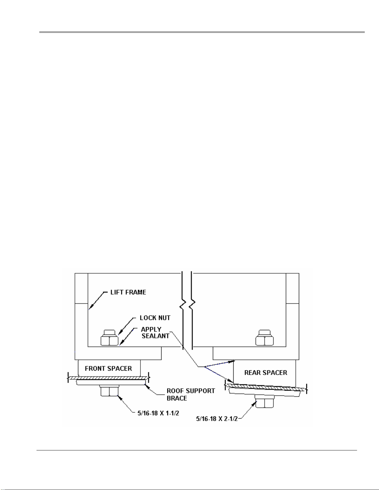
MOUNTING ..................................................................................................................................................................................... 7
CONTROL BOX POCKET MOUNTING ............................................................................................................................................... 8
6. ELECTRICAL WIRING............................................................................................................................................................. 8
7. MAINTENANCE.......................................................................................................................................................................... 8
8. POWER FAILURE...................................................................................................................................................................... 8
REMOVE THE ARROW BOARD ACTUATOR FIRST. ............................................................................................................................. 8
RETRACT THE LIFT ARM.................................................................................................................................................................. 9
9. PARTS BREAKDOWN............................................................................................................................................................. 10
10. TECHNICAL SPECIFICATIONS ......................................................................................................................................... 11
11. WIRING SCHEMATIC........................................................................................................................................................... 13
12. LIMITED WARRANTY.......................................................................................................................................................... 15
1/3/2006