LS-378 User’s Manual
-7-
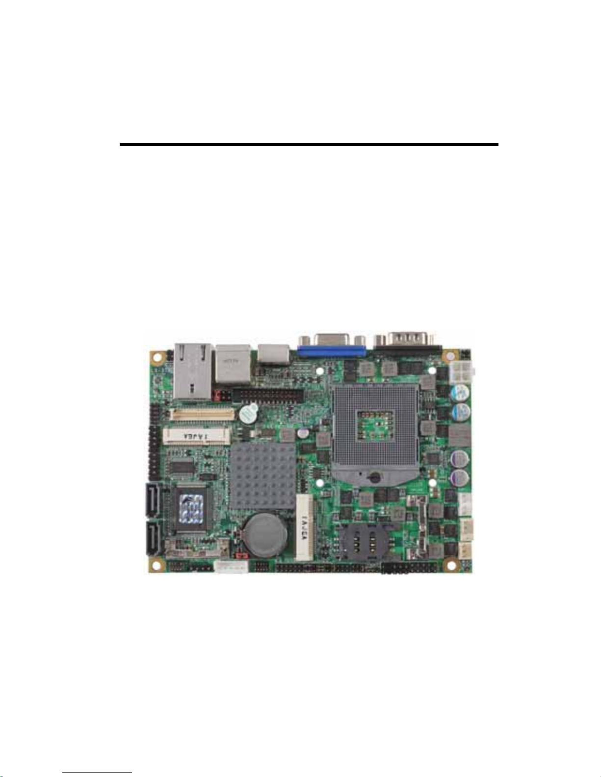
1.2 <Product Specification>
General Specification
Form Factor 3.5 inch motherboard
CPU 2nd Generation Intel® Core™ i7, Core™ i5, Core™ i3 and Celeron®
Mobile Processor
Package type: rPGA988B
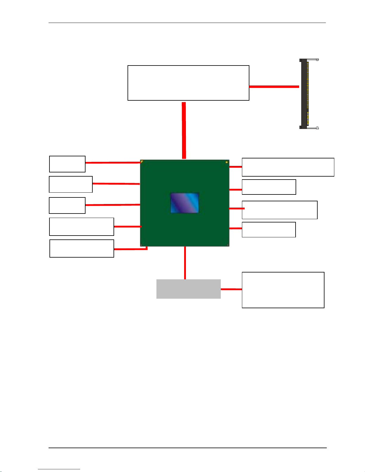
Memory 1 x DDRIII SO-DIMM 1066/1333/1600 MHz up to 8GB
Non-ECC, unbuffered memory supported only
Chipset Intel QM67
Real Time Clock Chipset integrated RTC with onboard lithium battery
Watchdog Timer Generates a system reset with internal timer for 1min/s ~255min/s
Power Management Supports ACPI 2.0 compliant,
Serial ATA Interface 2 x serial ATAIII interface with 600MB/s transfer rate
Support RAID 0, 1and Intel Rapid Storage Technology
VGA Interface Onboard DSUB15 connector for VGA interface
LVDS Interface Onboard 24-bit dual channel LVDS connector with +3.3V/+5V/+12V
supply
DVI Interface Chrontel CH7318 Transmitter with 26-pin DVI connector
Audio Interface Realtek ALC888 HD Audio
LAN Interface Intel 82579LM Gigabit LAN
GPIO interface Onboard programmable 8-bit Digital I/O interface
Extended Interface 2 x PCIE mini card socket,1 x SIM socket
Internal I/O Port 1 x RS232/422/485, 1 x SMBUS, 1 x GPIO, 4 x USB2.0 ports, 1 x IrDA,
1 x DVI ,1 x LVDS, 2 x Serial ATAIII, 1 x Front panel Audio and 1 x CDIN
External I/O Port 1 x PS/2, 1 x LAN port, 1 x VGA port, 2 x USB2.0 ports and 1 x RS232
Power Requirement 9~24V full range DC Input
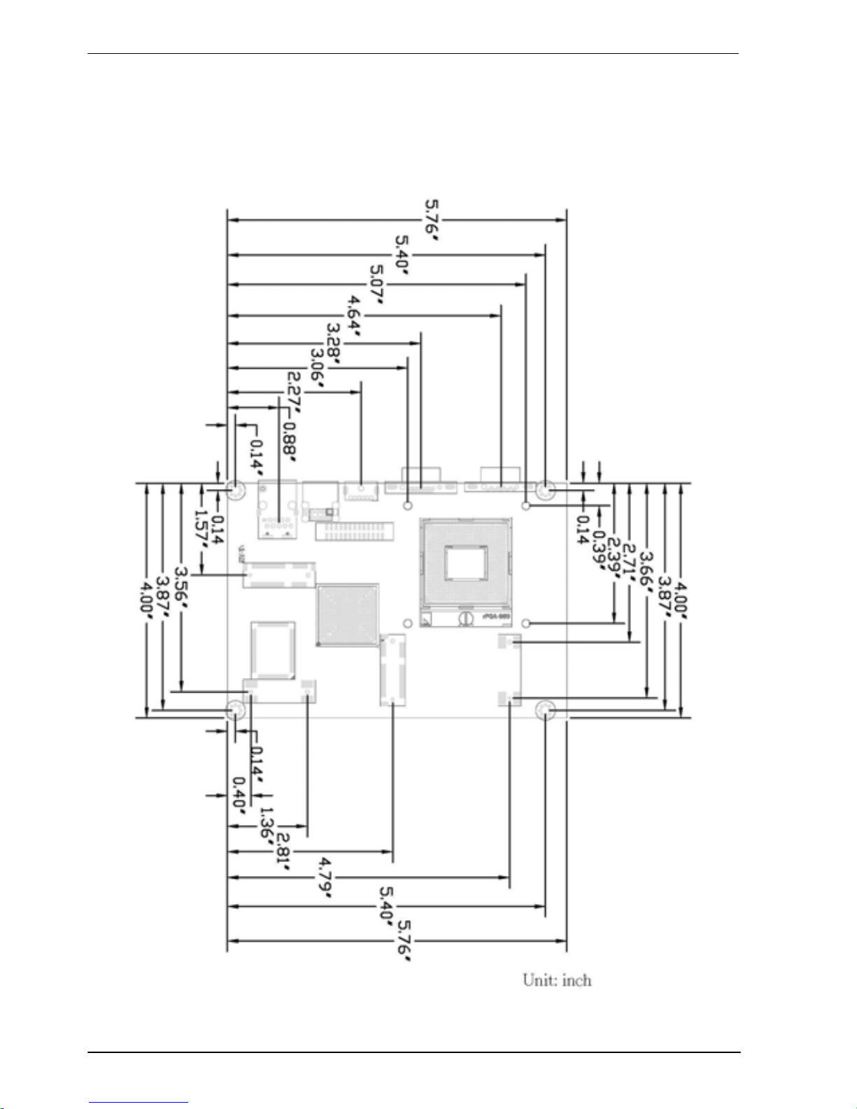
Dimension 146mm x 101mm
Temperature Operating within 0~60 centigrade
Storage within –20~85 centigrade
Ordering Code
LS-378DXT Intel PGA988B+ QM67 Onboard VGA, LVDS, DVI, LAN, USB2.0,
HD Audio, SATAIII, SMBUS, LPC, SIM, GPIO, PCI Express mini card.
The specifications may be different as the actual production.
For further product information please visit the website at TUhttp://www.commell.com.twUT