Commell FS-977PRO User manual

FS-977PRO
User’s Manual
Edition 1.0
Copyright
Copyright©2002, 2003. All rights reserved. This document is copyrighted and
all rights are reserved. The information in this document is subject to change
without prior notice to make improvements to the products.
This document contains proprietary information and protected by copyright.
No part of this document may be reproduced, copied, or translated in any
form or any means without prior written permission of the manufacturer.
All trademarks and/or registered trademarks contains in this document are
property of their respective owners.
Disclaimer
Taiwan Commate Computer Inc. shall not be liable for any incidental or
consequential damages resulting from the performance or use of this product.
Taiwan Commate Computer Inc. does not issue a warranty of any kind,
express or implied, including without limitation implied warranties of
merchantability or fitness for a particular purpose.
The company has the right to revise the manual or include changes in the
specifications of the product described within it at any time without notice and
without obligation to notify any person of such revision or changes.
Trademark
All trademarks are the property of their respective holders.
Any question please visit our website at http://www.commell.com.tw.
FS-977PRO User’s Manual 1

Packing List
Hardware
FS-977 Single Board Computer........................................ X 1
Cable Kit
34-pin FDD Cable ............................................................. X 1
TV-out Cable with bracket................................................. X 1
1 x COM / 1 x LPT Port DB9 / DB25 Cable (VL only)........ X 1
2 x COM Port DB9 Cable (VL2 only)................................. X 1
1 x LPT Port DB25 Cable (VL2 only) ................................ X 1
Dual-USB Port Cable with Bracket.................................... X 2
PS/2 Keyboard and Mouse Cable..................................... X 1
40-pin UltraATA/100 IDE Cable........................................ X 2
Audio Cable ...................................................................... X 1
3-pin to 4-pin ATX cable.................................................... X 1
Printed Matter and Software
User’s Manual................................................................... X 1
Driver CD.......................................................................... X 1
FS-977PRO User’s Manual
2

Table of Content
Chapter 1. Introduction ......................................................................5
1.1 Product Overview..................................................................................5
1.2 Specification..........................................................................................6
1.3 Component Placement .........................................................................9
1.4 Block Diagram.....................................................................................10
Chapter 2. Hardware Setup.................................................................11
2.1 Jumper and Connector Location ................................................................. 11
2.1.1 Jumper Reference.............................................................................12
2.1.2 Connector Reference........................................................................13
2.2 CPU and DRAM Setting......................................................................14
2.3 CMOS Setting.....................................................................................14
2.4 Watchdog Timer Setting......................................................................15
2.5 Embedded Solid State Disk ................................................................16
2.6 Power and Fan Connector..................................................................17
2.7 VGA Interface .....................................................................................18
2.7.1 Standard Analog VGA Interface.......................................................18
2.7.2 Digital VGA Interface.........................................................................19
2.7.3 TV-out Interface.................................................................................21
2.8 Ethernet Interface ...............................................................................22
2.9 Audio Interface....................................................................................23
2.10 Switch and Indicator............................................................................24
Chapter 3. BIOS Setup......................................................................25
Chapter 4. Driver Installation...........................................................27
FS-977PRO User’s Manual 3

Appendix. A I/O Port Pin Assignment.............................................29
A.1 IDE Port.............................................................................................. 29
A.2 Floppy Port......................................................................................... 30
A.3 Parallel Port........................................................................................ 31
A.4 Serial Port........................................................................................... 32
A.4.1 Onboard RS-232C Serial Port ..........................................................32
A.4.2 On Bracket RS-232C Serial Port......................................................32
A.5 USB Port ............................................................................................ 33
A.6 IrDA Port............................................................................................. 33
A.7 VGA Port ............................................................................................ 34
A.8 LAN Port............................................................................................. 34
A.9 AT Keyboard Port ............................................................................... 35
A.10 PS/2 Keyboard and Mouse Port......................................................... 35
Appendix B.Flash the BIOS................................................................37
B.1 BIOS Auto Flash Tool ......................................................................... 37
B.2 Flash Method...................................................................................... 37
Appendix C. System Resource........................................................39
C.1 I/O Port Address Map......................................................................... 39
C.2 Memory Address Map......................................................................... 40
C.3 IRQ and DMA Resource..................................................................... 41
Contact Information.............................................................................44
FS-977PRO User’s Manual
4

Chapter 1. Introduction
1.1 Product Overview
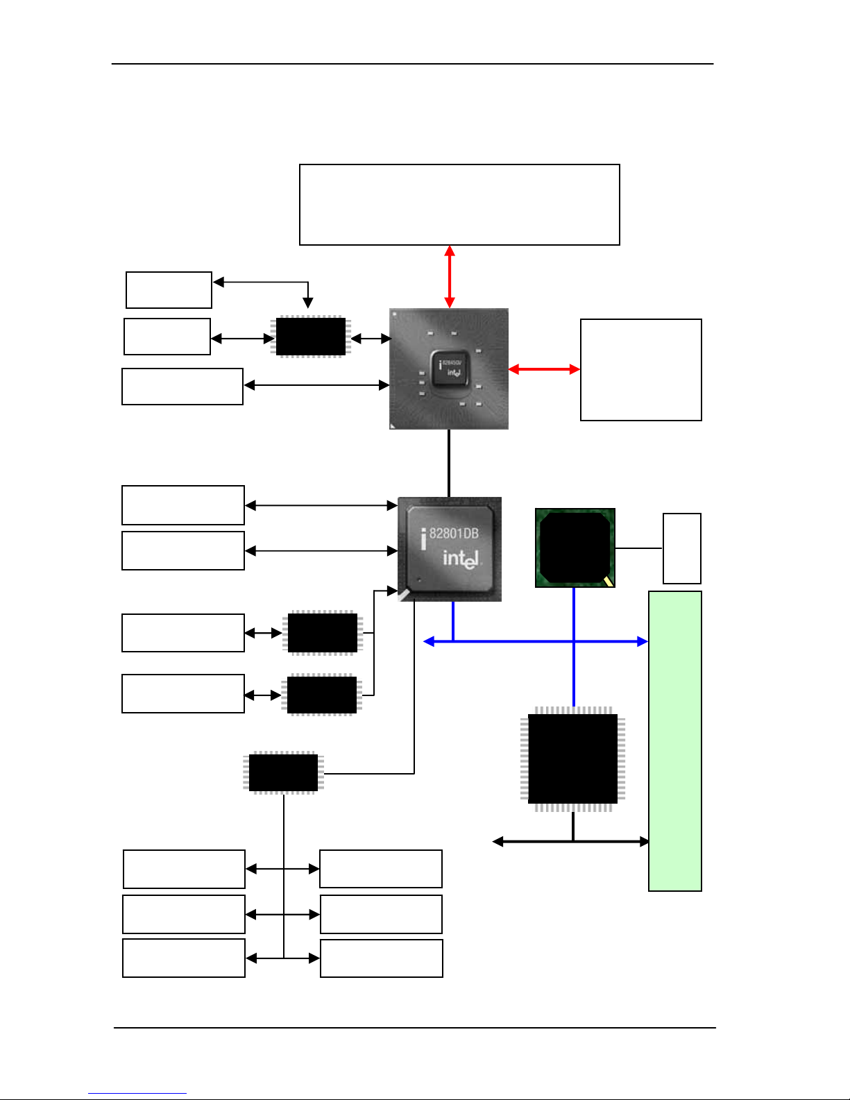
The FS-977PRO SBC (Single Board Computer) is an all-in-one industrial
full-size PICMG (PCI/ISA)-bus CPU card based on Intel Socket 478 Pentium
4 architecture. With Intel Brookdale-GV chipset, Intel 845GV GMCH and ICH4,
FS-977PRO offers the value computing solution including Intel NetBurst
micro-architecture, 533/400 MHz of FSB, 2GB DDR SDRAM, Intel Extreme
Graphics with 266 MHz VGA core, 256-bit 3D engine, Intel Dynamic Video
Memory up to 64 MBytes, LVDS interface, TV-out, one Intel PRO/100+ LAN
and one Intel PRO/1000+ LAN, Hi-Speed USB 2.0 and M-systems
DiskOnChip solid state flash disk interfaces.
Based on the Intel's long term supply chipset in the EIA (Embedded Intel
Architecture) division’s product roadmap, FS-977PRO should be the ideal
solution for the industrial applied computing platform with high computing
capacity, cost effect and long life cycle. With Intel’s latest technology, the
FS-977PRO should be the leading edge of computing capacity for the
advanced industrial computing platform with the features as below.
Intel Hyper-Threading Technology
The FS-977PRO supports Intel Hyper-Threading Technology to offer the
better computing capacity for the industrial applied computing application.
Based on Intel's latest technology, "the Intel Pentium 4 Processor with
Hyper-Threading technology allows software programs to "see" two
processors and work more efficiently. Improves performance and system
responsiveness in today's multitasking environments by enabling the
processor to execute instruction threads in parallel."
Powerful Computing Capacity
With Intel’s latest CPU technology, FS-977PRO supports Intel Socket 478
Pentium 4 CPU up to 3.06 GHz at 533 MHz of FSB and low cost Intel Socket
478 Celeron CPU up to 2.4 GHz at 400 MHz of FSB. The FS-977PRO also
provides two GBytes of DDR200/266/333 of system memory capacity.
Hi-Speed USB 2.0 Interface:
Intel ICH4 built-in Hi-Speed USB 2.0 controller offers the Hi-Speed USB 2.0
interface with up to 480 Mbps of data transfer bandwidth with the USB
bootable setting in the BIOS.
FS-977PRO User’s Manual 5

1.2 Specification
General Specification
Form Factor Full-size PICMG-bus CPU Card / Slot PC
PICMG version 1.0 (Rev. 2.0), PCI version 2.0 compliant
CPU Intel Socket 478 Pentium 4 / Celeron CPU
at 400/533 MHz FSB (100/133MHz x 4)
Intel 0.13-/0.18-micron Northwood / Willamette CPU
Support Intel Hyper-Threading Technology
Memory Two 184-pin DIMM sockets support up to 2 GBytes
DDR200/266/333 SDRAM.
(No ECC/register DIMM support)
Chipset Intel 82845GV GMCH and 82801DB ICH4
BIOS Phoenix-Award 2Mb PnP flash BIOS
Green Function Power saving mode supported in BIOS with DOZE,
STANDBY and SUSPEND modes. ACPI version 1.0 and
APM version 1.2 compliant
Watchdog Timer Generates NMI or system reset programmable watchdog
timer with 1 to 255 sec./min. of time out value
Real Time Clock Intel ICH4 built-in RTC with onboard lithium battery
Enhanced IDE PCI enhanced IDE interface supports dual ports up to 4
ATAPI devices with UltraATA/100 supported
Jumper selectable Vcc power output on IDE2 for power
cable free DOM (DiskOnModule) flash disk
ISA High Drive ISA 64mA high Drive capacity with TI 245 buffer on both
of ISA address and data bus
Solid State Disk Interface
Flash Type M-systems DiskOnChip 2000, DiskOnChip Millennium,
IDE Pro and DiskOnModule (DOM) solid state flash disk
Package 32-pin DIP JEDEC (DiskOnChip)
40-pin IDE port (DOC IDE Pro, DiskOnModule)
Capacity 1GB of DiskOnChip and 512 MB of DiskOnModule
FS-977PRO User’s Manual
6

Multi-I/O Port
Chipset Intel 82801DB ICH4 and Winbond W83627HF-AW LPC
super-I/O controller
Serial Port Two RS-232 serial ports. Both with 16C550 compatible
UART and 16 bytes FIFO.
USB 2.0 Port Four Hi-Speed USB 2.0 ports with Intel ICH4
Support 480 Mbps of data transfer rate
Parallel Port One bi-direction parallel port with SPP/ECP/EPP mode
Floppy Port One floppy port supports up to two FDD
IrDA Port One IrDA compliant Infrared interface supports SIR
K/B & Mouse PS/2 keyboard and mouse ports, AT keyboard port
VGA Display Interface
Chipset Intel 845GV GMCH built-in Intel Extreme Graphics with
266 MHz VGA core
Video Memory Intel Dynamic Video Memory with auto detect video
memory up to 64 MBytes shared with system memory
Display Type CRT and LCD monitor
LVDS Color LCD
LCD Interface 24-bit single/dual channel LVDS interface
Connector External DB15 female connector on bracket for CRT
Dual Internal 20-pin header for LVDS interface
Internal 16-pin header for analog VGA display
TV-out Interface
Chipset Intel 845GV GMCH built-in Intel Extreme Graphics with
Chrontel CH7017A-T TV-out encoder
TV Mode Support both of NTSC and PAL mode
Connector Internal 8-pin header for TV-out interface
FS-977PRO User’s Manual 7

Ethernet Interface
Chipset One Intel PRO/100+ LAN interface and one Intel
PRO/1000+ LAN interface
Primary LAN (LAN1): Intel ICH4 with Intel 82562ET PHY
Secondary LAN (LAN2): PCI Intel 82540EM
Type LAN1:10Base-T / 100Base-TX,
auto-switching Fast Ethernet
Full duplex, IEEE802.3U compliant
LAN2: 10Base-T / 100Base-TX/1000Base-T
auto-switching Fast Ethernet
Full duplex, IEEE802.3, 802.3u, 802.3ab compliant
Audio Interface
Chipset Intel ICH4 built-in AC97 3D audio controller with codec
Interface Line-in, line-out, CD-in, Mic-in
Power and Environment
Power Req. +5V, +12V, -12V DC input from PICMG backplane
Additional +12V on 4-pin connector for Pentium 4 PSU
ATX Function 3-pin ATX interface with 5V standby and power-on
Dimension 338 (L) x 122 (H) mm, standard PICMG form factor
Temperature Operating within 0 ~ 60oC (32 ~ 140oF)
Storage within -20 ~ 85oC (-4 ~ 185oF)
EMI
Ordering Code
FS-977PROVXL Full-size PICMG Socket 478 Pentium 4 DDR CPU Card
with 533/400 MHz FSB, Intel Extreme Graphics, Intel
PRO/100+ LAN , LVDS interface, TV-out, Audio,
Hi-Speed USB 2.0, DOC Socket and ISA 64mA High Drive
Capacity
FS-977PROVXL2 Same as FS-977PROVL but
with Intel PRO/100+ LAN and Intel PRO/1000+ LAN
FS-977PRO User’s Manual
8

1.3 Component Placement
ITE8888 ISA Bridge
Winbond 83627HF-AW
LPC Su
p
er-I
/
O
2 x 184-pin DIMM Sockets
System Memory
2 GB DDR200/266/333
Intel 845GV GMCH
Built-in Intel
Extreme Graphics
mPGA478 CPU Socket
Intel Pentium 4 / Celeron
533/400 MHz FSB
Intel 82801DB ICH4
Built-in Hi-Speed
USB 2.0 Interface
Intel PRO/100+ LAN
Intel ICH4 with 82562ET
Intel PRO/1000+ LAN
with 82540EM
FS-977PRO User’s Manual 9

1.4 Block Diagram
Intel Socket 478 Pentium 4 / Celeron CPU
Intel 0.13-/0.18-micron Northwood / Willamette
Support Intel Hyper-Threading Technology
FSB 400 / 533 MHz
100 / 133 MHz x 4
TV
LVDS
Encoder
LCD
LAN2
Two 184-pin
DIMM Sockets
up to 2 GBytes
DDR SDRAM
UltraATA100 IDE
100 MBps
DDR266
DDR333
ATAPI Device
ISA Bus Interface
Intel
266 Mbps
Hub
-
Link
Intel 845GV
GMCH
CRT
AT Keyboard
PS/2 Mouse Floppy
Serial Device Parallel Device
LPC
SIO
PS/2 Keyboard
Hi-Speed USB 2.0
480 Mbps Intel ICH4
PCI Bus Interface
Intel
82540EM
iTE 8888
PCI-ISA
Bridge
PICMG Backplane
LAN1 PHY
Codec
Audio Devices
USB Devices
LVDS
FS-977PRO User’s Manual
10

Chapter 2. Hardware Setup
This chapter contains the information for installation of hardware. The install
procedure includes jumper settings, CPU and memory installation, fan, I/O
and panel connections.
2.1 Jumper and Connector Location
USB2 USB1 SYSFAN CRT LAN1 LAN2(COM1 for VXL)
FDD
LPT
JIR
DOC
IDE2
IDE1
JDOM
JRTC
CN_TV
JLVDS2
JLVDS1
DIMM2
DIMM1
CPU
JPS
JFRNT
PS2
JATKB
JCOM2
JCOM1
JLAN2
JDOC
JWDT
JAUDIOJ
JWOL
CDIN
CN_INV
JVLCD
CPUFAN
ATXREG
FS-977PRO User’s Manual 11

2.1.1 Jumper Reference
Jumper Function Section
JRTC COMS Operate / Clear Setting 2.3
JWDT Watchdog Timer NMI / Reset Setting 2.4
JDOC DiskOnChip SSD Address Setting 2.5
JDOM DiskOnModule SSD Power Setting 2.5
JVLCD Flat Panel’s Voltage Setting 2.7.2
JLAN2 Secondary LAN Enable/Disable Setting 2.8
FS-977PRO User’s Manual
12

2.1.2 Connector Reference
Internal Onboard Connector
Connector Function Remark
CPU MicroPGA478 CPU Socket Standard
DIMM1/2 184-pin DIMM Socket Standard
IDE1/2 40-pin Primary / Secondary IDE Port Standard
FDD 34-pin Floppy Port Standard
LPT 26-pin Parallel Port Standard
JCOM1/2 10-pin COM1/2 Serial Port Standard
USB1/2 10-pin 1st / 2nd (3rd / 4th) USB Port Standard
JIR 5-pin SIR IrDA Port Standard
DOC 32-pin DIP DiskOnChip Socket Standard
JATKB 5-pin AT Keyboard Connector Standard
ATXREG 4-pin Additional +12V Power Connector Standard
JPS 3-pin ATX Signal Connector Standard
JFRNT 14-pin Switch and Indicator Connector Standard
CPUFAN 3-pin +12V CPU Fan Connector Standard
SYSFAN 3-pin +12V System Fan Connector Standard
JVGA 16-pin Internal VGA Port Standard
JAUDIO 10-pin Audio Port Standard
CDIN 4-pin CD-in Interface Standard
WOL 3-pin Wake-On-LAN Interface Standard
JLVDS1 20-pin LVDS interface Standard
JLVDS2 20-pin LVDS interface Standard
CN_INV 5-pin Backlight Inverter power connector Standard
CN_TV TV-out interface Standard
External Connector on Bracket
Connector Function Remark
VGA DB15 Female VGA Connector Standard
LAN1 RJ45 LAN1 Connector Standard
LAN2 RJ45 LAN2 Connector VXL2 only
COM1 DB9 Male COM1 Connector VXL only
PS2 6-pin MiniDIN PS/2 Keyboard & Mouse Standard
FS-977PRO User’s Manual 13

FS-977PRO User’s Manual
14
2.2 CPU and DRAM Setting
The board is based on Intel Socket 478 architecture with Intel 845GV
chipset, supports Intel Socket 478 Pentium 4 / Celeron CPU at 533/400
MHz FSB.
System memory of this board supports up to 2 GBytes DDR200/266/333
SDRAM on two 184-pin DIMM sockets. Please notices that Intel 845GV
GMCH DOESN’T support ECC and register DIMM.
2.3 CMOS Setting
The board’s data of CMOS can be setting in BIOS. If the board refuses to
boot due to inappropriate CMOS settings, here is how to proceed to clear
(reset) the CMOS to its default values.
Jumper: JRTC
Type: onboard 3-pin header
JRTC Mode
1-2 Clear CMOS
2-3 Normal Operation
Default setting
JRTC
13

2.4 Watchdog Timer Setting
The watchdog timer makes the systems auto-reset while it stop to work for
a period. The onboard watchdog timer can be setup as system reset or
active NMI mode by jumper JWDT.
Jumper: JWDT
Type: onboard 3-pin header
JWDT Watchdog Timer
1-2 Active NMI
2-3 Reset
Default setting
JWDT
1
2
3
Program Sample
Watchdog timer setup as system reset with 5 second of timeout
2E, 87
2E, 87
2E, 07
2F, 08 Logical Device 8
2E, 30 Activate
2F, 01
2E, F5 Set as Second*
2F, 00
2E, F6 Set as 5
2F, 05
* Minute: bit 3 = 0; Second: bit 3 = 1
FS-977PRO User’s Manual 15

977PRO User’s Manual
16 S-
2.5 Embedded Solid State Disk
The board supports both 32-pin M-systems DiskOnChip 2000 and IDE-based
DiskOnChip IDE Pro and DiskOnModule (DOM) embedded flash disk. The
onboard 32-pin socket, DOC, supports DiskOnChip 2000 single chip flash
disk in 32-pin DIP JEDEC with jumper selectable address on jumper JDOC;
onboard 40-pin IDE2 box header supports normal DOM (DiskOnModule) or
M-systems DiskOnChip IDE Pro flash disk with jumper selectable +5V Vcc
power for cable free applications on jumper JDOM.
123
JDOC
JDOM
12
DiskOnChip 2000 Address Setting
Jumper: JDOC
Type: onboard 3-pin header
JDOC DiskOnChip Address
1-2 D000h
2-3 D800h
Default setting
DOM or DiskOnChip 2000 IDE Pro Power Setting
Jumper: JDOM
Type: onboard 2-pin header
JDOM +5V on Pin-20 of IDE2
OFF (Open) Disable
ON (Close) Enable
Default setting
F

2.6 Power and Fan Connector
JPS
13
123
SYSFAN
CPUFAN
ATXREG
31
42
Connector: ATXREG
Type: 4-pin standard Pentium 4 additional +12V power connector
Pin Description Pin Description
1 Ground 2 Ground
3 +12V 4 +12V
Connector: JPS
Type: 3-pin ATX wafer connector
Pin Description Pin Description Pin Description
1 5V_Standby 2 Ground 3 Power_on
Connector: CPUFAN, SYSFAN
Type: 3-pin fan wafer connector
Pin Description Pin Description Pin Description
1 Ground 2 +12V 3 Fan Control
FS-977PRO User’s Manual 17

2.7 VGA Interface
2.7.1 Standard Analog VGA Interface
The board is integrated with Intel 845GV GMCH chipset built-in Intel
Extreme Graphics with 266 MHz VGA core, 256-bit 3D engine and Intel
Dynamic Video Memory up to 64 MBytes shared with system memory. The
CRT / analog VGA interface includes one external DB15 female connector
on bracket and one internal 16-pin header on board.
JVGA
19
8 16
Connector: JVGA
Type: 16-pin (2 x 8) 2.54-pitch header
Pin Description Pin Description
1 Red 9 Green
2 Blue 10 N/C
3 Ground 11 Ground
4 Ground 12 Ground
5 N/C 13 Ground
6 N/C 14 Data
7 HSYNC 15 VSYNC
8 Clock 16 N/C
FS-977PRO User’s Manual
18

2.7.2 Digital VGA Interface
The board provides an LVDS Interface, with Intel 845GV GMCH built-in
Intel Extreme Graphics with CHRONTEL CH7017A-T encoder.
JLVDS1
JLVDS2
CN_INV
15
2
20
1
19
JVLCD
13
Jumper: JVLCD
Type: onboard 3-pin header
JVOLT1 LCD Voltage Setting
1-2 +5V
2-3 +3.3V
Default setting
FS-977PRO User’s Manual 19

LVDS TFT/DSTN LCD Interface
Connector: JLVDS1,
Type: onboard 20-pin Hirose DF13-20DP-1.25V
Pin Signal Pin Signal
1 VCCLCD 2 VCCLCD
3 GND 4 GND
5 A0- 6 A0+
7 GND 8 A1-
9 A1+ 10 GND
11 A2- 12 A2+
13 GND 14 CLK1-
15 CLK1+ 16 GND
17 A3- 18 A3+
19 GND 20 GND
Connector: JLVDS2
Type: onboard 20-pin Hirose DF13-20DP-1.25V
Pin Signal Pin Signal
1 VCCLCD 2 VCCLCD
3 GND 4 GND
5 A4- 6 A4+
7 GND 8 A5-
9 A5+ 10 GND
11 A6- 12 A6+
13 GND 14 CLK2-
15 CLK2+ 16 GND
17 A7- 18 A7+
19 GND 20 GND
LCD Backlight Inverter Power Connector
Connector: CN_INV
Type: 5-pin wafer connector
Pin Description
1 +12V
2 Ground
3 Ground
4 Ground
5 ENABKL
FS-977PRO User’s Manual
20
Table of contents
Other Commell Motherboard manuals

Commell
Commell LE-37G User manual

Commell
Commell LV-67T User manual

Commell
Commell LP-172 User manual

Commell
Commell LP-170 User manual

Commell
Commell LE-37N7 User manual

Commell
Commell FS-A71 User manual

Commell
Commell LS-377 User manual

Commell
Commell LV-67TK7 User manual

Commell
Commell LE-565 User manual

Commell
Commell HS-770 User manual

Commell
Commell LV-667 User manual

Commell
Commell LV-67M User manual

Commell
Commell LE-370 User manual

Commell
Commell LV-67O User manual

Commell
Commell LV-668 User manual

Commell
Commell HS-873P User manual

Commell
Commell MX-7794 User manual

Commell
Commell LE-37A User manual

Commell
Commell ETB-ITX1 User manual

Commell
Commell LP-173 User manual