Commell LS-37B User manual

-1-
LS-37B
3.5 inch Motherboard
User’s Manual
Edition 1.0
2012/09/20

-2-
Copyright
Copyright 2012, all rights reserved. This document is copyrighted and all rights are
reserved. The information in this document is subject to change without prior notice to
make improvements to the products.
This document contains proprietary information and protected by copyright. No part of
this document may be reproduced, copied, or translated in any form or any means
without prior written permission of the manufacturer.
All trademarks and/or registered trademarks contains in this document are property of
their respective owners. Disclaimer
The company shall not be liable for any incidental or consequential damages resulting
from the performance or use of this product.
The company does not issue a warranty of any kind, express or implied, including
without limitation implied warranties of merchantability or fitness for a particular purpose.
The company has the right to revise the manual or include changes in the specifications
of the product described within it at any time without notice and without obligation to
notify any person of such revision or changes.
Trademark
All trademarks are the property of their respective holders.
Any questions please visit our website at TUhttp://www.commell.com.twUT

LS-37B User’s Manual
-3-
Packing List:
Please check the package content before you starting using the board.
Hardware:
LS-37B 3.5“ Miniboard x 1
Cable Kit:
SATA Cable x 1
(OALSATA-L)
Printed Matters:
Driver CD (Including User’s Manual) x 1
CPU Cooler x 1
(OHS-P-M-H)
DC Power Cable x 1
(OALDC-A)
USB2.0 Cable x 1
(OALUSBA-3)
PS/2 Keyboard & Mouse Cable x 1
(OALPS2/MK)
COM Port Cable x 1
(OALES-BKU1NB)
Audio Cable x 1
(OALPJ-HDUNB)
1 to 3 power output cable x 1
(OAL4P-2)
SATA Power Cable x 1
(OAL4P-S2)
DVI module with bracket x 1
(ADPDVI & OALDVI-DF13)

LS-37B User’s Manual
-4-
Optional Cable:
USB3.0 Cable
(OALUSB3NB)

LS-37B User’s Manual
-5-
Index
Chapter 1 <Introduction>..............................................................................8
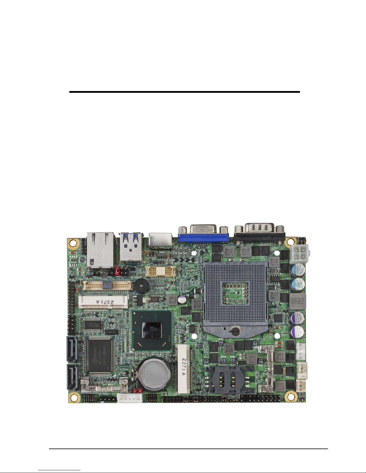
1.1 <Product Overview>.....................................................................................8
1.2 <Product Specification>................................................................................9
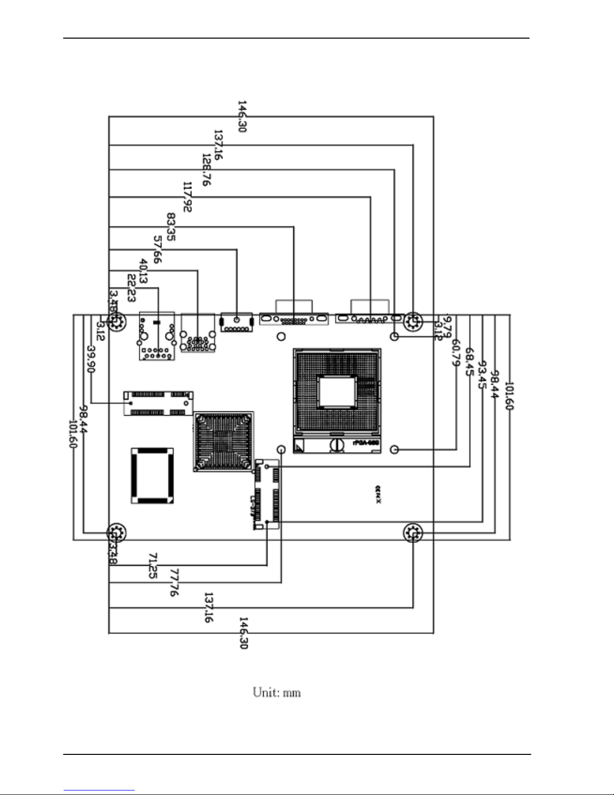
1.3 <Mechanical Drawing>...............................................................................10
1.4 <Block Diagram>........................................................................................ 11
Chapter 2 <Hardware Setup>......................................................................12
2.1 <Connector Location>................................................................................12
2.2 <Jumper Location & Reference>................................................................14
2.3 <Connector Reference>.............................................................................15
2.3.1 <Internal Connectors> ...................................................................15
2.3.2 <External Connectors>..................................................................15
2.4 <CPU and Memory Setup> ........................................................................16
2.4.1 <CPU Setup>.................................................................................16
2.4.2 <Memory Setup> ...........................................................................17
2.5 <CMOS & ATX Setup>...............................................................................18
2.6 <Serial ATA Interface>................................................................................19
2.7 <Ethernet Interface>...................................................................................19
2.8 <Onboard Display Interface> .....................................................................20
2.8.1 <Analog Display>...........................................................................20
2.8.2 <Digital Display>............................................................................21
2.8.3 <DVI Interface>..............................................................................25
2.9 <Integrated Audio Interface>......................................................................26
2.10 <USB Interface>.......................................................................................27
2.11 <Serial Port>.............................................................................................29
2.12 <PCIE Mini Card and SIM Interface>.......................................................31
2.12.1 <SIM Setup>................................................................................33
2.13 <GPIO and SMBUS Interface>.................................................................35
2.14 <Power Supply and Fan Interface >.........................................................36
2.14.1 <Power Input> .............................................................................36
44-pin

LS-37B User’s Manual
-6-
2.14.2 <Power Output>...........................................................................36
2.14.3 <Fan connector>..........................................................................37
2.15 <Switch and Indicator> .............................................................................38
Chapter 3 <System Setup> .........................................................................39
3.1 <Audio Configuration>................................................................................39
3.2 <Display Properties Setting> ......................................................................40
Chapter 4 <BIOS Setup> .............................................................................42
Appendix A <I/O Port Pin Assignment>.....................................................44
A.1 <Serial ATA Port> .......................................................................................44
A.2 <IrDA Port>.................................................................................................44
A.3 <VGA Port>................................................................................................44
A.4 <LAN Port>.................................................................................................44
A.5 <LAN LED Port>.........................................................................................45
A.6 <LPC Port>.................................................................................................45
Appendix B <Flash BIOS>...........................................................................46
B.1 <Flash Tool>...............................................................................................46
B.2 <Flash BIOS Procedure> ...........................................................................46
Appendix C <Programming GPIO’s> .........................................................47
Appendix D <Programming Watchdog Timer > ........................................48
Contact Information.....................................................................................49

LS-37B User’s Manual
-7-
(This page is left for blank)

LS-37B User’s Manual
-8-
Chapter 1 <Introduction>
1.1 <Product Overview>
LS-37Bthe 3rd Generation Intel of the 3.5 inch miniboard, supports 3rd Generation Intel®
Core™ i7, Core™ i5, Core™ i3 Mobile Processor and features Intel QM77 chipset,
integrated HD Graphics, DDR3 memory, REALTEK High Definition Audio, Serial ATA
and Intel Gigabit LAN.
Intel Ivy Bridge Processor
The 3rd Generation Intel® Core™ processor family mobile is the next generation of
64-bit, multi-core mobile processor built on 22- nanometer process technology. Based
on a new micro-architecture.
New features for Intel QM77 chipset
The board integrates Intel QM77 chipset, supports integrated HD Graphics, built-in high
speed mass storage interface of serial ATA, High Definition Audio with 2 channels
surrounding sound.
All in One multimedia solution
Based on Intel QM77 chipset, the board provides high performance onboard graphics,
24-bit dual channel LVDS interface, DVI and 2 channels High Definition Audio, to meet
the very requirement of the multimedia application.
Flexible Extension Interface
The board provides two PCIE mini card socket.

LS-37B User’s Manual
-9-
1.2 <Product Specification>
General Specification
Form Factor
3.5 inch motherboard
CPU
3rd Generation Intel® Core™ i7, Core™ i5, Core™ i3 Mobile Processor
Package type: rPGA988B
Memory
1 x DDRIII SO-DIMM 1066/1333/1600 MHz up to 8GB
Non-ECC, unbuffered memory supported only
Chipset
Intel QM77
Real Time Clock
Chipset integrated RTC with onboard lithium battery
Watchdog Timer
Generates a system reset with internal timer for 1min/s ~255min/s
Power Management
Supports ACPI 3.0 compliant,
Serial ATA Interface
2 x serial ATAIII interface with 600MB/s transfer rate
VGA Interface
Onboard DSUB15 connector for VGA interface
LVDS Interface
Onboard 24-bit dual channel LVDS connector with +3.3V/+5V/+12V
supply
DVI Interface
Onboard DVI with 20-pin connector
Audio Interface
Realtek ALC888 HD Audio
LAN Interface
Intel 82579LM Gigabit LAN
GPIO interface
Onboard programmable 8-bit Digital I/O interface
Extended Interface
2 x PCIE mini card socket,1 x SIM socket
(Optional support mSATA(SATAII) for Mini_Card2)
Internal I/O Port
1 x RS232/422/485, 1 x SMBUS, 1 x GPIO, 2 x USB3.0 ports, 2 x USB2.0
ports,1 xIrDA, 1 x DVI ,1 x LVDS, 2 x Serial ATAIII, 1 x Front panel Audio and
1 xCDIN
External I/O Port
1 x PS/2, 1 x LAN port, 1 x VGA port, 2 x USB3.0 ports and 1 x RS232
Power Requirement
9~24V full range DC Input
Dimension
146mm x 101mm
Temperature
Operating within 0~60 centigrade
Storage within –20~85 centigrade
Ordering Code
LS-37B
Intel PGA988B + QM77 Onboard VGA, DVI, LVDS, LAN, USB3.0,
USB2.0, HD Audio, SATAIII, SMBUS, GPIO, SIM
and PCI Express mini card.
LS-37BS
Intel PGA988B + QM77 Onboard VGA, DVI, LVDS, LAN, USB3.0,
USB2.0, HD Audio, SATAIII, SMBUS, GPIO, SIM,
PCI Express mini card and mSATA.
The specifications may be different as the actual production.
For further product information please visit the website at TUhttp://www.commell.com.twUT

LS-37B User’s Manual
-10-
1.3 <Mechanical Drawing>

LS-37B User’s Manual
-11-
1.4 <Block Diagram>
QM77
1 x Intel 82579LM
1 x RS232/422/485
1 x COM & GPIO & IrDA
1 x PS/2
3rd Generation Intel® Core™ i7,
Core™ i5, Core™ i3
Mobile Processor
1 x 204-pin DDR3
SO-DIMM
1066/1333/1600 MHz
up to 8GB
IO W83627DHG-P
1 x LVDS
2 x PCI Express mini card
1 x DVI
1 x CRT
2 x Serial ATAIII
ALC888 HDAudio
4 x USB3.0
2 x USB2.0

LS-37B User’s Manual
-12-
Chapter 2 <Hardware Setup>
2.1 <Connector Location>
SATA1
SATA2
CN_AUDIO
CD_IN
CN_INV
CN_COM2
CN_DIO
CN_SMBUS
CN_IR
JFRNT
SYSFAN
CPUFAN
DC_OUT
DC_IN
CN_USB1
CN_USB3-0
CN_LPC
CN_LVDS
CN_DVI
SIMM
MINI_CARD2
MINI_CARD1
JACT
JSPD
CN_LVDS

LS-37B User’s Manual
-13-
PS2
RJ45
CRT
COM1
SO-DIMM
USB

LS-37B User’s Manual
-14-
2.2 <Jumper Location & Reference>
Jumper
Function
JRTC
CMOS Operating/Clear Setting
JVLCD
Panel Voltage Setting
JAT
Power mode select
JP1
Com1 Voltage Setting (For Pin 9)
JP2
Com2 Voltage Setting (For Pin 9)
JCSEL1
JCSEL2
CN_COM2 RS-232 RS422 RS485 Setting
CN_IR IrDA Setting
JP1
JVLCD
JRTC
JCSEL1
JCSEL2
JP2
JAT

LS-37B User’s Manual
-15-
2.3 <Connector Reference>
2.3.1 <Internal Connectors>
Connector
Function
Remark
CPU
Socket rPGA988B for PGA988 CPU
SO-DIMM
204 -pin DDR3 SO-DIMM socket
SATA 1/2
7-pin Serial ATAIII connector
DC_IN
DC 9~24V input connector
DC_OUT
4-pin DC output connector
CN_AUDIO
5 x 2-pin audio connector
CD_IN
4-pin CD-ROM audio input connector
CN_DIO
6 x 2-pin digital I/O connector
CN_USB 1/2
5 x 2-pin USB connector
CPUFAN
4-pin CPU cooler fan connector
SYSFAN
3-pin system cooler fan connector
CN_DVI
10 x 2-pin DVI connector
CN_LVDS
20 x 2-pin LVDS connector
CN_INV
5-pin LCD inverter connector
CN_IR
5-pin IrDA connector
CN_COM2
9-pin RS232/485/422
CN_LPC
5 x 2-pin LPC connector
JFRNT
10-pin front panel switch/indicator
connector
Mini-PCIE1/2
52-pin Mini-PCIE socket
JAT
Power mode select
JSPD
LAN Speed LED connector
JACT
LAN Activity LED connector
2.3.2 <External Connectors>
Connector
Function
Remark
COM1
DB9 Serial port connector
CRT
DB15 VGA connector
PS2
PS/2 keyboard and mouse connector
USB
Dual USB 3.0 connector
RJ45
RJ45 LAN connector

LS-37B User’s Manual
-16-
2.4 <CPU and Memory Setup>
2.4.1 <CPU Setup>
The board comes with the socket rPGA988 for Intel Ivy Bridge Processor, Please
follow the instruction to install the CPU properly.
1. Use the flat-type screw drive
to unlock the CPU socket
Unlock way
Check point
2. Follow the pin direction to install
the processor on the socket
3. Lock the socket
Socket CPU
Check point

LS-37B User’s Manual
-17-
2.4.2 <Memory Setup>
The board provides 204-pin DDR3 SO-DIMM to support 1066/1333/1600MHz DDR3
memory module up to 8GB.
SO-DIMM

LS-37B User’s Manual
-18-
2.5 <CMOS & ATX Setup>
The board‟s data of CMOS can be setting in BIOS. If the board refuses to boot due
to inappropriate CMOS settings, here is how to proceed to clear (reset) the CMOS
to its default values.
Jumper: JRTC
Type: Onboard 3-pin jumper
JRTC
Mode
1-2
Clear CMOS
2-3
Normal Operation
Default setting: 2-3
Jumper: JAT
Type: onboard 3-pin jumper
JAT
Mode
1-2
AT Mode
2-3
ATX Mode
Default setting:2-3
JRTC
JAT
1 3
1 3

LS-37B User’s Manual
-19-
2.6 <Serial ATA Interface>
Based on Intel PCH, the board provides two Serial ATAIII (SATA Port1/2) interfaces with
up to 600MB/s of transfer rate .
2.7 <Ethernet Interface>
The board integrates with one Intel 82579LM controllers, The Intel Gigabit Ethernet
supports triple speed of 10/100/1000Base-T, with IEEE802.3 compliance.
RJ45 LAN connector
SATA1
SATA2

LS-37B User’s Manual
-20-
2.8 <Onboard Display Interface>
Based on Intel Ivy Bridge CPU with built-in HD Graphic, the board provides one DB15
connector on real external I/O port, one 40-pin LVDS interface with 5-pin LCD backlight
inverter connector and provides 20-pin DVI interface.
The board provides dual display function with clone mode and extended desktop mode
for CRT, LCD and DVI.
2.8.1 <Analog Display>
Please connect your CRT or LCD monitor with DB15 male connector to the onboard
DB15 female connector on rear I/O port.
CRT
Other manuals for LS-37B
1
Table of contents
Other Commell Motherboard manuals

Commell
Commell LE-37E User manual

Commell
Commell LS-372 User manual

Commell
Commell LV-677 User manual

Commell
Commell LE-37N User manual

Commell
Commell LV-67B User manual

Commell
Commell LV-676 User manual

Commell
Commell LP-180 User manual

Commell
Commell P3WA Series User manual

Commell
Commell LS-371 User manual

Commell
Commell LE-578 User manual

Commell
Commell ME-C79 User manual

Commell
Commell LV-602 User manual

Commell
Commell LP-177 User manual

Commell
Commell FE-97G User manual

Commell
Commell LE-37DJIP User manual

Commell
Commell ETB-ITX1 User manual

Commell
Commell LV-67E User manual

Commell
Commell LV-67M User manual

Commell
Commell LE-37R User manual

Commell
Commell LE-37C-G User manual