Commell LV-67S User manual

LV-67S
Mini-ITX Desktop Motherboard
User’s Manual
Edition 2.0
2016/06/27

LV-67S User’s Manual
-1-
Copyright
Copyright 2015, all rights reserved. This document is copyrighted and all rights are reserved.
The information in this document is subject to change without prior notice to make
improvements to the products.
This document contains proprietary information and protected by copyright. No part of this
document may be reproduced, copied, or translated in any form or any means without prior
written permission of the manufacturer.
All trademarks and/or registered trademarks contains in this document are property of their
respective owners.
Disclaimer
The company shall not be liable for any incidental or consequential damages resulting from
the performance or use of this product.
The company does not issue a warranty of any kind, express or implied, including without
limitation implied warranties of merchantability or fitness for a particular purpose.
The company has the right to revise the manual or include changes in the specifications of
the product described within it at any time without notice and without obligation to notify any
person of such revision or changes.
Trademark
All trademarks are the property of their respective holders.
Any questions please visit our website at TUhttp://www.commell.com.twUT

LV-67S User’s Manual
-2-
Packing List:
Please check the package content before you starting using the board.
Printed Matters:
Driver CD (Including User’s Manual) x 1
1 x LV-67S Mini-ITX Motherboard
1 x PS/2 Keyboard & Mouse cable
(OALPS2/KMB) / (1040610)
1 x Audio cable
(OALPJ-HD) / (1040120)
1 x USB2.0 Cable
(OALUSBA-1) / (1040172)
1 x Dual COM PORT Cable
(OALES-BKU2) / (1040087)
1 x USB3.0 Cable
(OALUSB3) / (1040531)
2 x SATA Cable
(OALSATA3-L) / (1040529)
OPTIONAL:
1 x VGA Cable
(OALVGA-SNB-7) / (1040557)
1 x I/O Shield
(OPLATE-CDILAT) / (1270067)

LV-67S User’s Manual
-3-
Index
Chapter 1 <Introduction>............................................................... 4
1.1 <Product Overview>............................................................4
1.2 <Product Specification> ......................................................5
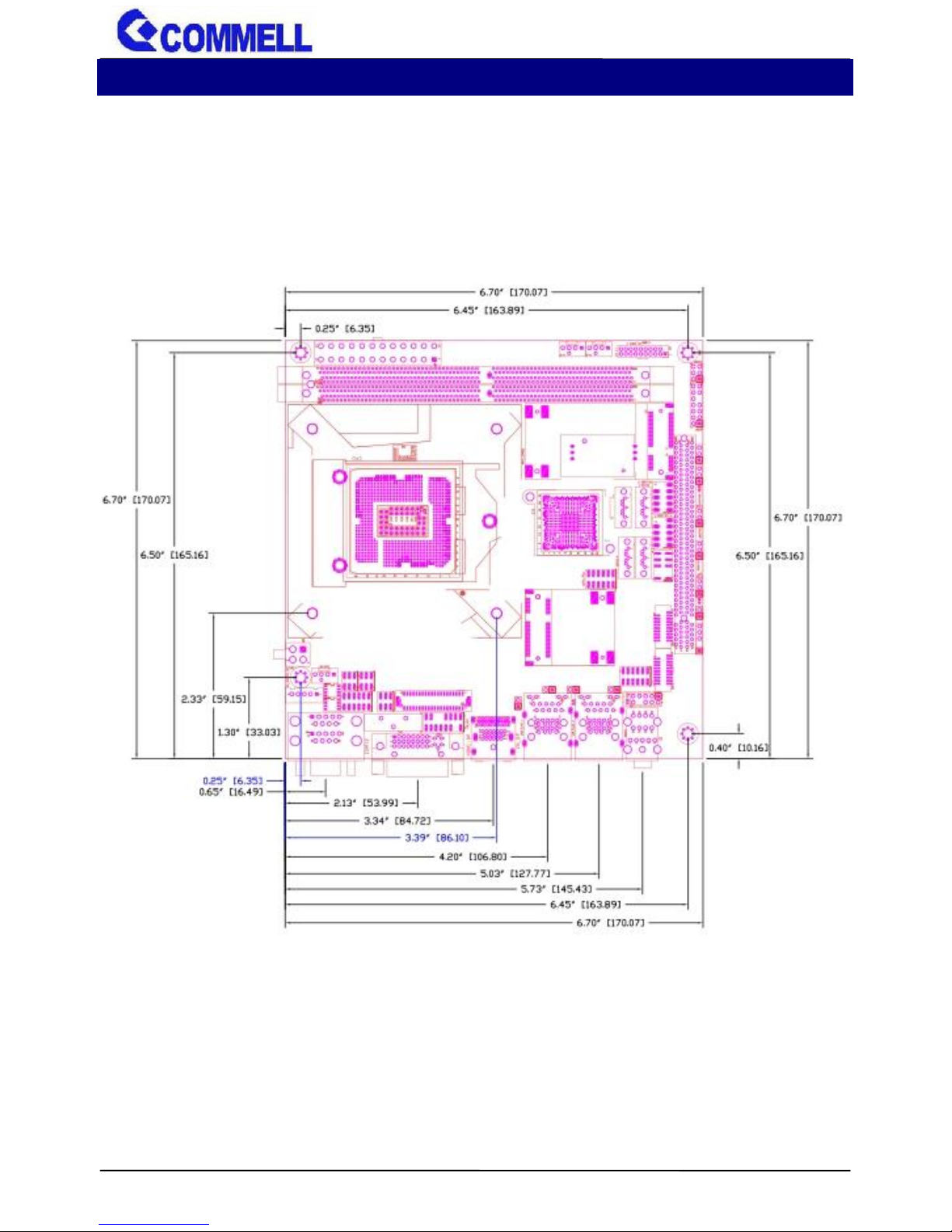
1.3 <Mechanical Drawing>........................................................6
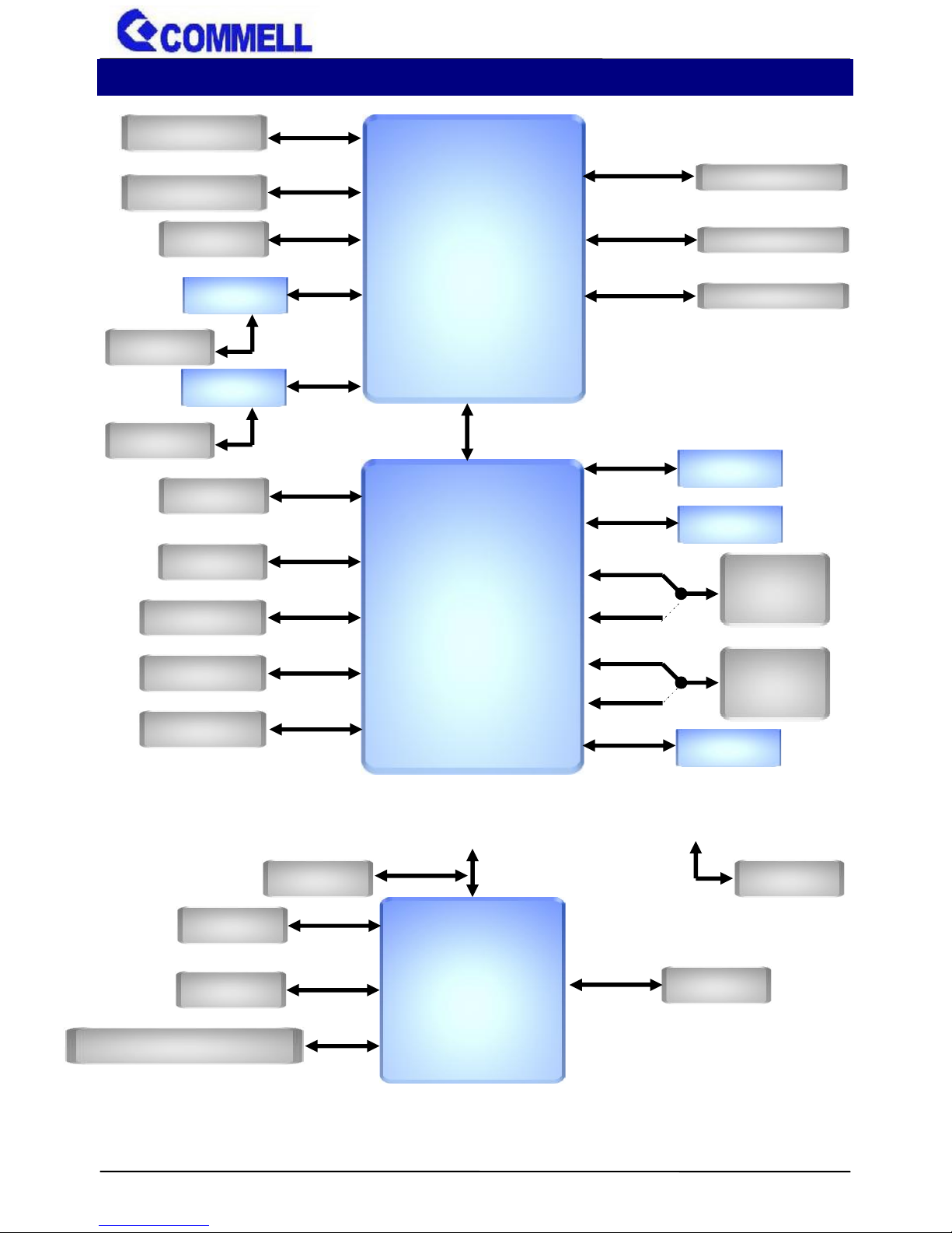
1.4 <Block Diagram>.................................................................7
Chapter 2 <Hardware setup>.........................................................8
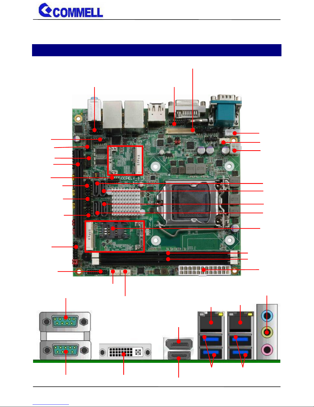
2.1 <Connector Location and Reference> ................................8
2.1.1 <Internal connectors list> ..........................................9
2.1.2 <External connectors list>.........................................9
2.2 <CPU and Memory Setup> ...............................................10
2.2.1 <CPU installation> ..................................................10
2.2.2 <Memory Setup> .................................................... 11
2.3 <Jumper Location and Reference> ...................................12
2.3.1 <Jumper list> ..........................................................12
2.3.2 <Clear CMOS and Power on type selection>..........13
2.4 <I/O interface> ..................................................................13
2.4.1 <Serial ATA interface>.............................................13
2.4.2 <Ethernet interface>................................................14
2.4.3 <Display interface> .................................................14
2.4.4 <Serial Port interface> ............................................17
2.4.5 <USB interface>......................................................19
2.4.6 <Audio interface>....................................................21
2.4.7 <Expansion slot>.....................................................22
2.4.8 <Front panel switch and indicator> ......................... 23
2.4.9 <GPIO and Other interface> ...................................24
2.5 <Power supply> ................................................................ 26
2.5.1 <Power input>.........................................................26
Appendix A <Flash BIOS> ........................................................... 27
Appendix B <LCD Panel Type select> ........................................27
Appendix C <Programmable Watch Dog Timer>....................... 29
Appendix D <Hardware monitor > .............................................. 30
Appendix E <Programmable GPIO > ..........................................31
Appendix F <RAID Setting>......................................................... 32
Contact information ..................................................................... 33

LV-67S User’s Manual
-4-
Chapter 1 <Introduction>
1.1 <Product Overview>
LV-67S is Mini-ITX Motherboard which supports 6th Generation Intel® Core™ i7, i5, i3,
S-series and Xeon® Processor with Intel® C236 Chipset, integrated HD Graphics 530,
DDR4 memory, Realtek High Definition Audio, Intel Gigabit LAN, Serial ATA3
Intel Skylake-S Processor with Intel® C236 Chipset PCH-H
The 6th Generation Intel® Core™ S-series and Xeon® processor family is new generation
and multi-core processor built on 14 nanometer process.
Skylake provide new HD Graphics 530 support triple displays at the same time, maximum
supported is up to 32GB of DDR4, better performance, flexibility and more enhanced
security that is suitable for a variety of intelligent systems the ideal choice.
All in One multimedia solution
LV-67S provides high performance onboard graphics, 18/24-bit single/dual channel LVDS
interface, DisplayPort, DVI-I, CRT and High Definition Audio, to meet the requirement of the
multimedia application.
Flexible Expansion Interface
It includes two minicard slot, PCIEX16 slot, 6 com port, 6 USB3.0, and 4 USB2.0.
Skylake remove EHCI
When you install WIN7 with USB device(CDROM, Keyboard, Mouse...), Windows7 can not
identify your usb device. You can use SATA CD-ROM and PS/2 to install Windows7.

LV-67S User’s Manual
-5-
1.2 <Product Specification>
System
Processor
Intel® Skylake Core™ i7, i5, i3 S-series and Xeon® E3-1200 v5 Product
Family Processor, FCLGA1151 package
Chipset
Intel® C236 PCH-H
Memory
2 x DDR4 DIMM 1866/2133 MHz up to 32GB, Support Non-ECC,
unbuffered memory only
Watchdog Timer
Generates a system reset with internal timer for 1min/s ~ 255min/s
Real Time Clock
Chipset integrated RTC with onboard lithium battery
Expansion
1 x MiniPCIe (support mSATA)
1 x Half Size MiniPCie (support mSATA)
1 x Sim slot
1 x PCIE X16 slot
Graphics
Chipset
Intel® 9th Gen integrated HD Graphics
(Some Xeon® E3-1200 v5 Product don’t have)
Display Interface
1 x DVI-I, 1 x DisplayPort(optional),
1 x LVDS, 1 x HDMI, 1 x CRT
LAN
Chip
1 x Intel® I219-LM Gigabit PHY LAN
(Support iAMT11.0)
1 x Intel® I210-AT Gigabit LAN
I/O
Serial ATA
4 x SATA3
Audio
Realtek ALC262 HD Audio
Internal I/O
4 x SATA3, 4 x RS232, 4 x USB2.0, 2 x USB3.0, 1 x LVDS, 1 x LPC
1 x LCD inverter, 1 x GPIO , 1 x Audio, 1 x PS/2, 1 x SMBUS, 1 x CRT
Rear I/O
1 x DisplayPort(optional), 1 x DVI-I, 1 x HDMI, 4 x USB3.0,
2 x LAN, 1 x RS232/422/485, 1 x RS232, 1 x Audio.
Mechanical & Environmental
Power Requirement
Standard 24-pin ATX power supply and 4-pin 12V
Size & Thickness
170mm x 170mm (L x W)
Temperature
Operating within 0°C~60°C (32°F~140°F)
Storage within -20°C~80°C (-4°F~176°F)
Relative Humidity
10%~90%, non-condensing

LV-67S User’s Manual
-6-
1.3 <Mechanical Drawing>

LV-67S User’s Manual
-7-
1.4 <Block Diagram>
CPU
6th
Gen Processor
C236
PCH-H
1 x DisplayPort
1 x DVI-I
PTN3460
1 x LVDS
SIO
NCT6106D
DDI
Channel A
eDP
eDP
4 x SATA3
SATA3
6 x USB3.0
4 x USB2.0
USB3.0
USB2.0
SPI Flash
SPI
PCIe x1
I219-LM
HDA
HD Audio
PCIe x1
SATA3
LPC
1 x LPC
ALC262
5 x RS232
1 x SMBUS
MiniPCIe
/ mSATA
1 x RS232/RS422/RS485
SMBus
1 x CRT
1 x HDMI
DDI
DDI
DDR4 DIMM 1.2V
Channel B
1 x GPIO
MiniPCIe
/ mSATA
1 x PS/2
SATA3
PCIe x1
PTN3355
DMI GEN3
DDR4 DIMM 1.2V
PCIe x1
I210-AT
PCI Express X16
PEG

LV-67S User’s Manual
-8-
Chapter 2 <Hardware setup>
2.1 <Connector Location and Reference>
CN_LVDS
CN_LPC
CN_AUDIO
SATA3-1
CN_PS2
JFRNT
I219-LM
COM2
CN_CRT
I210-AT
COM1
DVI-I
HDMI
Display Port
AUDIO
USB3.0
USB3.0
CN_USB2-2
CN_USB2-1
PCI_E16X
CN_COM3/4
CN_COM5/6
CN_DIO
SATA3-2
SATA3-3
SATA3-4
CN _INV
MINI_CARD1
CPUFAN
CN_12V
ATX
MINI_CARD2
DDR4_A
CN_USB 3-1
DDR4_B
SYSFAN
AUXFAN
SIMM

LV-67S User’s Manual
-9-
2.1.1 <Internal connectors list>
Connector
Function
DDR4_A/B
288-pin DDR4 DIMM slot
SATA3-1/2/3/4
7-pin Serial ATA3 connector
CN_AUDIO
5 x 2-pin audio pin header
CN_LPC
6 x 2-pin LPC pin header
CN_LVDS
20 x 2-pin LVDS connector
CN_INV
5-pin LCD inverter connector
CN_SMBUS
5-pin SMBus connector
CN_COM 3/4/5/6
20-pin RS232 connector
CN_USB 2-1/2-2
5 x 2-pin USB2.0 pin header
CN_USB 3-1
10 x 2-pin USB3.0 pin header
CN_PS2
5 x 2-pin PS/2 pin header
CN_DIO
6 x 2-pin digital I/O connector
CN_CRT
16-pin VGA connector
CPUFAN
4-pin CPU fan connector
SYSFAN
4-pin system fan connector
AUXFAN
4-pin system fan connector
JFRNT
14-pin front panel switch/indicator connector
PCI_E16X
164-pin x16 PCIE slot
MINI_CARD1
52-pin Half-MiniPCIe card slot
MINI_CARD2
52-pin MiniPCIe card slot
ATX
24-pin power supply connector
CN_12V
4-pin power input Terminal Block
SIMM
6-pin socket
2.1.2 <External connectors list>
Connector
Function
DisplayPort
DisplayPort connector
DVI-I
DVI connector
HDMI
HDMI connector
USB3.0
4 x USB3.0 connector
LAN
2 x RJ45 connector
AUDIO
Audio connector
COM1/2
DB9 Serial port connector

LV-67S User’s Manual
-10-
2.2 <CPU and Memory Setup>
2.2.1 <CPU installation>
LV-67S has a LGA1151 CPU socket onboard; please check following steps to install the
processor properly.
Attention If LV-67S need RMA please Keep CPU socket cover on the CPU Socket.
Warning If CPU Socket internal Pin damage We could not provide warranty.
1. Lift this bar
2. Uncover this plate
Intel® Skylake Core™ i7, i5, i3 S-series and Xeon®
E3-1200 v5 Processor, FCLGA1151 package
Checked point
3. Place the CPU on the top of the pins
4. Cover this plate
5. Lock this bar

LV-67S User’s Manual
-11-
2.2.2 <Memory Setup>
LV-67S has two 288-pin DDR4 DIMM support up to 32GB of memory capacity and 1.2
Voltage. The memory frequency supports 1866/2133 MHz. Only Non-ECC memory is
supported.
Please check the pin number to match the socket side well
before installing memory module.

LV-67S User’s Manual
-12-
2.3 <Jumper Location and Reference>
2.3.1 <Jumper list>
Jumper
Function
JAT
Power mode select
JRTC
CMOS Normal/Clear Setting
JVLCD
Panel Voltage Setting
JMSATA1
MiniCard 1 MSATA Setting
JMSATA2
MiniCard 2 MSATA Setting
JP1
COM1 Voltage Setting (For Pin 9)
JP2
COM2 Voltage Setting (For Pin 9)
JCSEL1
COM2 RS-232 RS422 RS485 Setting
JCSEL2
COM2 RS-232 RS422 RS485 Setting
JVSATA3-2
Set 5V to SATA3-2 pin 7 (For SATADOM)
JVUSB
USB Voltage Setting
JAT
JVLCD
JMSATA2
JMSATA1
JRTC
JAUXTIN
JVUSB
CN_SMBUS
JP2
JCSEL2
JCSEL1
JP1
JVSATA3-2

LV-67S User’s Manual
-13-
2.3.2 <Clear CMOS and Power on type selection>
The board’s data of CMOS can be setting in BIOS. If the board refuses to boot due to
inappropriate CMOS settings, here is how to proceed to clear (reset) the CMOS to its
default values.
JAT: AT/ATX mode select jumper
Jumper settings
Function
1-2
AT mode
2-3
ATX mode (Default)
JRTC: Clear CMOS data jumper
Jumper settings
Function
1-2
Clear CMOS
2-3
Normal (Default)
2.4 <I/O interface>
2.4.1 <Serial ATA interface>
SATA 1/2/3/4: SATA3 7-pin connector
JVSATA3-2: SATA3/SATADOM mode select jumper (change pin7 to 5V)
Jumper settings
Function
1-2
SATA3-2 SATADOM
2-3
SATA3-2 SATA3 (Default)
Pin
Signal
1
GND
2
TX+
3
TX-
4
GND
5
RX-
6
RX+
7
GND
7
1
SATA3-1
SATA3-2
SATA3-3
SATA3-4
JVSATA3-2
JRTC
1
3
JAT
1
3
1
3

LV-67S User’s Manual
-14-
2.4.2 <Ethernet interface>
The board provide I219-LM PHY Gigabit Ethernet and I210-AT Gigabit Ethernet on
rear I/O.Intel I219-LM and I210 supports operation at 10/100/1000 Mb/s data rates,
with IEEE802.3 compliance and Wake-On-LAN supported.
2.4.3 <Display interface>
Based on the 6th Gen CPU with built-in HD Graphics 530, CRT and DVI up to
1920x1080@60Hz, DisplayPort up to 4096x2304@60Hz , HDMI up to
4096x2304@24Hz on rear IO. About the internal Display, LVDS (PTN3460) up to
1920x1200@60Hz support 18/24-bit color depth and single/dual channel. About
select LCD Panel Type in BIOS, please refer Appendix B.
The built-in HD Graphics support triple display function with clone mode and
extended mode.
I219-LM
I210-AT
DISPLAY PORT
HDMI
DVI-I

LV-67S User’s Manual
-15-
CN_CRT: CRT 16-pin connector (Pitch 2.00 mm)
Pin
Signal
Pin
Signal
1
BR
2
BG
3
BB
4
NC
5
IOGND1
6
IOGND1
7
IOGND1
8
IOGND1
9
NC
10
IOGND1
11
NC
12
5VCDA
13
5HSYNC
14
5VSYNC
15
5VCLK
16
NC
CN_LVDS: LVDS 40-pin connector (Model: HIROSE DF13-40DP-1.25V compatible)
Pin
Signal
Pin
Signal
2
Set by JVLCD
1
Set by JVLCD
4
Detect (Active low)
3
GND
6
A_LVDS_0-
5
B_LVDS_0-
8
A_LVDS_0+
7
B_LVDS_0+
10
GND
9
GND
12
A_LVDS_1-
11
B_LVDS_1-
14
A_LVDS_1+
13
B_LVDS_1+
16
GND
15
GND
18
A_LVDS_2-
17
B_LVDS_2-
20
A_LVDS_2+
19
B_LVDS_2+
22
GND
21
GND
24
A_LVDS_CLK-
23
B_LVDS_3-
CN_LVDS
JVLCD
1
39
2
40
6
5
2
1
5
1
CN_INV
CN_CRT
15
16
2
1

LV-67S User’s Manual
-16-
26
A_LVDS_CLK+
25
B_LVDS_3+
28
GND
27
GND
30
A_LVDS_3-
29
B_LVDS_CLK-
32
A_LVDS_3+
31
B_LVDS_CLK+
34
GND
33
GND
36
LVDS_DDCSCL
35
NC
38
LVDS_DDCSDA
37
NC
40
NC
39
NC
Note: Pin4 only need to be connected to GND
CN_INV: LVDS 5-pin Backlight power connector
Pin
Signal
1
12V
2
Backlight Control
3
GND
4
GND
5
Enable Backlight
JVLCD: LVDS panel power select jumper
Jumper settings
Function
1-2
3.3V (Default)
2-3
5V
5-6
12V

LV-67S User’s Manual
-17-
2.4.4 <Serial Port interface>
COM2
COM1
20
19
2
1
CN_COM3/4
CN_COM5/6
20
19
2
1
JP2
1
6
2
5
1
12
2
11
JCSEL2
JCSEL1
1
6
2
5
JP1
1
6
2
5

LV-67S User’s Manual
-18-
COM1: RS232 DB9 connector
Pin
Signal
Pin
Signal
1
DCD
2
RXD
3
TXD
4
DTR
5
GND
6
DSR
7
RTS
8
CTS
9
Set by JP1
COM2: RS232/422/485 DB9 connector
Pin
Signal
Pin
Signal
1
DCD/ 422TX-/ 485-
2
RXD/ 422TX+/ 485+
3
TXD/ 422RX+
4
DTR/ 422RX-
5
GND
6
DSR
7
RTS
8
CTS
9
Set by JP2
Use JCSEL1 and JCSEL2 to select communication mode
COM3/4: COM 20-pin header (Pitch 2.54 x 1.27mm)
Pin
Signal
Pin
Signal
1
DCD1
2
RXD1
3
TXD1
4
DTR1
5
GND
6
DSR1
7
RTS1
8
CTS1
9
RI1
10
NC
11
DCD2
12
RXD2
13
TXD2
14
DTR2
15
GND
16
DSR2
17
RTS2
18
CTS2
19
RI2
20
Key
COM5/6: COM 20-pin header (Pitch 2.54 x 1.27mm)
Pin
Signal
Pin
Signal
1
DCD1
2
RXD1
3
TXD1
4
DTR1
5
GND
6
DSR1
7
RTS1
8
CTS1
9
RI1
10
NC
11
DCD2
12
RXD2
13
TXD2
14
DTR2
15
GND
16
DSR2

LV-67S User’s Manual
-19-
17
RTS2
18
CTS2
19
RI2
20
Key
JP1, JP2: COM1, COM2 pin-9 setting
Jumper settings
Function
1-2
5V
3-4
12V
5-6
RI (Default)
Effective patterns of connection: 1-2 / 3-4 / 5-6
Other may cause damage
JCSEL1, JCSEL2: For configure COM2 communication mode
Function
JCSEL1
JCSEL2
RS232
RS485
RS422
2.4.5 <USB interface>
USB3.0
(LEFT)
1
12
2
11
2
6
1
5
2
6
1
5
1
12
2
11
USB3.0
(RIGHT)
1
12
2
11
2
1
5
6
Other manuals for LV-67S
1
Table of contents
Other Commell Motherboard manuals

Commell
Commell LV-679 User manual

Commell
Commell LV-67W User manual

Commell
Commell FS-A70 User manual

Commell
Commell MS-C75 User manual

Commell
Commell LV-67M User manual

Commell
Commell LS-372 User manual

Commell
Commell AS-C7A User manual

Commell
Commell LE-37C User manual

Commell
Commell LV-674 User manual

Commell
Commell LE-37A User manual

Commell
Commell LP-174 User manual

Commell
Commell PMCA User manual

Commell
Commell LE-37G User manual

Commell
Commell LV-67F User manual

Commell
Commell LV-672 User manual

Commell
Commell LV-67Z User manual

Commell
Commell LE-380 User manual

Commell
Commell HE-B72 User manual

Commell
Commell LS-371 User manual

Commell
Commell LE-370 User manual