Commell LP-173 User manual

LP-173
Pico-ITX
User’s Manual
2017/09/11
Version:1.60

LP-173 User’s Manual
-2-
Copyright
Copyright 2012. All rights reserved. This document is copyrighted and all rights are
reserved. The information in this document is subject to change without prior notice to
make improvements to the products.
This document contains proprietary information and protected by copyright. No part of
this document may be reproduced, copied, or translated in any form or any means
without prior written permission of the manufacturer.
All trademarks and/or registered trademarks contains in this document are property of
their respective owners.
Disclaimer
The company shall not be liable for any incidental or consequential damages resulting
from the performance or use of this product.
The company does not issue a warranty of any kind, express or implied, including
without limitation implied warranties of merchantability or fitness for a particular purpose.
The company has the right to revise the manual or include changes in the specifications
of the product described within it at any time without notice and without obligation to
notify any person of such revision or changes.
Trademark
All trademarks are the property of their respective holders.
Any questions please visit our website at TUhttp://www.commell.com.twUT

LP-173 User’s Manual
-3-
Packing List:
Please check the package content before you starting using the board.
Hardware:
LP-173 Pico-ITX Miniboard x 1
Cable Kit:
Printed Matters:
Driver CD x 1 (Including User’s Manual)
Audio Cable x 1
(OALPJ-HDUNB) / (1040123)
USB Cable x 1
(OALUSBA-3) / (1040173)
SATA Cable x 1
(OALSATA22B-PM15SH15) / (1040512)
DC_IN Power Cable x 1
(OALDC-B) / (1040513)
PS/2 Keyboard & Mouse Cable x 1
(OALPS2/KM) / (1040131)
CRT cable without bracket x 1
(OALVGA-SNB-7) / (1040557)
RS232 Cable x 1
(OALES-BKU2-H14NB) / (1040379)
Cooler
(OHSF-173) / (2181010017)
+
_

LP-173 User’s Manual
-4-
Index
Chapter 1 <Introduction> .................................................................................... 6
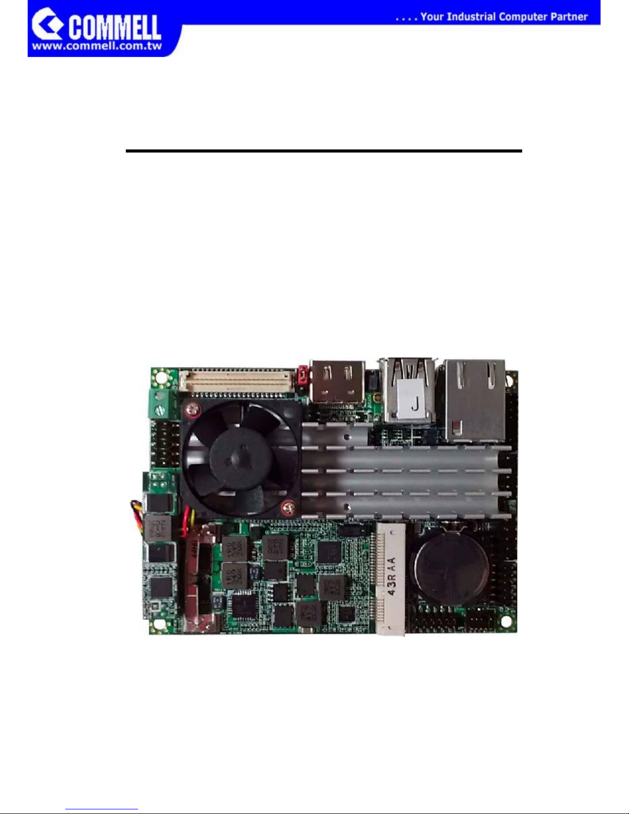
1.1 <Product Overview> .................................................................................. 6
1.2 <Product Specification>............................................................................. 7
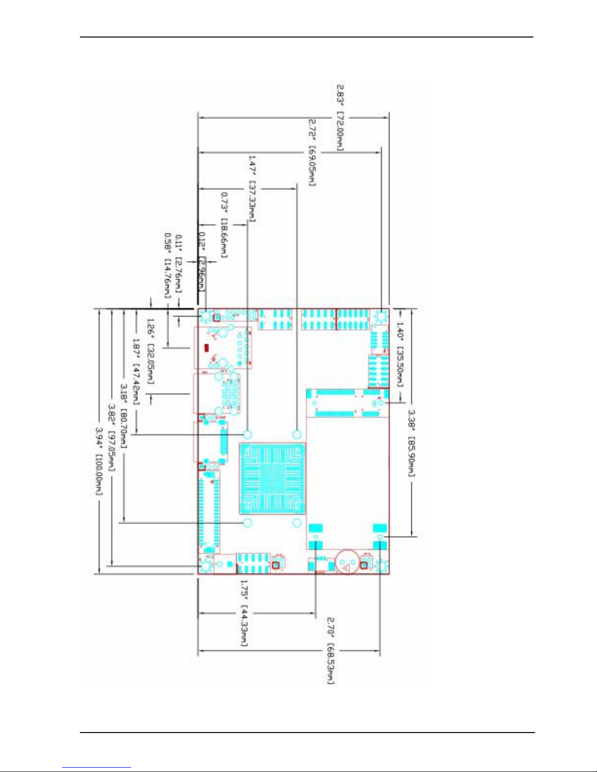
1.3 <Mechanical Drawing> .............................................................................. 8
1.4 <Block Diagram> ....................................................................................... 9
Chapter 2 <Hardware Setup>............................................................................ 10
2.1 <Connector Location> ........................................................................... ..10
2.2 <Jumper Reference>............................................................................... 11
2.3 <Connector Reference> .......................................................................... 11
2.3.1 <Internal Connector>.............................................................. 11
2.3.2 <External Connector> ............................................................ 11
2.4 <Memory Setup> ..................................................................................... 12
2.5 <CMOS & ATX Setup>............................................................................ 12
2.6 <SATA Interface> .................................................................................... 13
2.7 <LAN Interface> ...................................................................................... 13
2.8 <Onboard Display Interface> .................................................................. 13
2.8.1 <Analog VGA Interface> ........................................................ 13
2.8.2 <CN_LVDS> ........................................................................... 14
2.9 <Onboard Audio Interface> ..................................................................... 19
2.10 <USB 3.0 and USB 2.0Interface> ......................................................... 19
2.11 <Serial Port Jumper Setting > ............................................................... 23
2.12 <Power & FAN Connector >.................................................................. 24
2.12.1 <Power Input> ...................................................................... 24
2.12.2 <Power Output> ................................................................... 24
2.12.3 <Fan Connector> ................................................................. 25
2.13 <Indicator and Switch> .......................................................................... 26
2.14 < PCIE Mini Card >................................................................................ 27
Chapter 3 <BIOS Setup> ................................................................................... 28
44-pin

LP-173 User’s Manual
-5-
Appendix A <I/O Port Pin Assignment> .......................................................... 29
A.1 <SATA Port> ........................................................................................... 29
A.2 <LAN Port> ............................................................................................. 29
A.3 <LPC Port> ............................................................................................. 29
A.4 <GPIO Port> ........................................................................................... 30
Appendix B <Flash BIOS> ................................................................................ 31
B.1 BIOS Auto Flash Tool .............................................................................. 31
B.2 Flash Method .......................................................................................... 31
Appendix C <Programming GPIO’s> ............................................................... 32
Appendix D <Programming Watchdog Timer > .............................................. 33
Contact Information........................................................................................... 34

LP-173 User’s Manual
-6-
Chapter 1 <Introduction>
1.1 <Product Overview>
The LP-173 motherboard is design based on Intel® Celeron® Processor J1900 / N2930
and Intel® Atom Processor E3845, delivering outstanding compute, graphical, and
media performance while operating in an extended range of thermal conditions. The
SoC bases on the Silvermont microarchitecture, utilizing Intel’s industry-leading 22nm
process technology with 3-D Tri-Gate transistors, which deliver significant improvements
in computational performance and energy efficiency.
New features for Intel® Celeron® and Atom Processor
The Intel® Celeron® Processor J1900 / N2930 and Intel® Atom E3845 Processor
supports graphics, media performance, flexibility and more enhanced security that is
suitable for a variety of intelligent systems the ideal choice.
Outstanding integration of I/O interfaces
Supports display interfaces with graphics processing, camera interfaces with image
processing, audio with digital signal processing, multiple storage types, and legacy
embedded I/O. Provides interface expansion capabilities through industry-standard
high-bandwidth interfaces such as PCI Express* Gen 2.0, Hi-speed USB 2.0, and USB
3.0 connectivity.
All in One multimedia solution
Based on Intel® J1900 / N2920 /E3845 SoC, the board provides high performance
onboard graphics, CRT, 24-bit dual channel LVDS interface, HDMI and 2 channels High
Definition Audio, to meet the very requirement of the multimedia application.
Flexible Extension Interface
The board provides one PCIe mini slot

LP-173 User’s Manual
-7-
1.2 <Product Specification>
General Specification
Form Factor
PICO-ITX miniboard
CPU
Intel® Processor J1900/N2930/E3845, package type FCBGA1170
Memory
1 x DDR3L (support 1.35V) 1066/1333 SO-DIMM up to 8GB
Watchdog Timer
System reset programmable watchdog timer with 1 ~ 255 sec./min. of
timeout value
Real Time Clock
Chipset integrated RTC with onboard lithium battery
Serial ATA
1 x serial ATA interface with 300MB/s(3Gb/s) transfer rate
VGA Interface
Intel® Clear Video integrated HD Graphics Technology
LVDS Interface
1 x Onboard 24-bit dual channel LVDS connector with +3.3V/+5V
supply
Audio Interface
Realtek ALC262 High Definition Audio Codec
LAN Interface
1 x Intel® I210 Gigabit LAN
GPIO interface
Onboard programmable 8-bit Digital I/O interface.
Extended Interface
1 x PCIE Mini card or mSATA
Internal I/O Port
2 x RS232, 1 x GPIO, 1 x Audio connector, 1 x CRT, 1 x LVDS,
1 x LPC, 2 x USB 2.0(EHCI) and 1 x SATAII
External I/O Port
1 x HDMI port, 1 x RJ45 LAN port, 1 x USB 3.0(XHCI)/2.0(EHCI)
port,1 x USB 2.0(EHCI) port.
Power Requirement
6~27V DC Input
Dimension
100mm x 72mm
Temperature
Operating within 0~60 centigrade(for LP-173J and LP-173N serial)
Storage within -20~85 centigrade.(for LP-173J and LP-173N serial)
Operating within -40~85 centigrade(for LP-173E serial)
Storage within -40~85 centigrade.(for LP-173E serial)
Ordering Code
LP-173J
CPU J1900 (2M Cache, 2.42GHz), HDMI, LVDS, CRT
LP-173N
CPU N2930 (2M Cache, 2.16GHz), HDMI, LVDS, CRT
LP-173E
CPU E3845 (2M Cache, 1.91GHz), HDMI, LVDS, CRT

LP-173 User’s Manual
-8-
1.3 <Mechanical Drawing>

LP-173 User’s Manual
-9-
1.4 <Block Diagram>

LP-173 User’s Manual
-10-
Chapter 2 <Hardware Setup>
2.1 <Connector Location>

LP-173 User’s Manual
-11-
2.2 <Jumper Reference>
Jumper
Function
JRTC
CMOS Operating/Clear Setting
JAT
AT/ATX Mode Setting
JVLCD
LCD Panel Voltage Setting
JMSATA
Mini Card1 mSATA Setting
2.3 <Connector Reference>
2.3.1 <Internal Connector>
Connector
Function
SO-DIMM
204 -pin DDR3L SO-DIMM SDRAM slot
CN_SATA
10-pin SATA Cable connector
MINI_CARD
PCIE mini card socket
LVDS
20 x 2-pin LVDS connector
CN_INV
5-pin LCD inverter connector
CN_USB1/2
5 x 2-pin USB connector
CN_AUDIO
5 x 2-pin audio connector
CN_LPC
5 x 2-pin header for LPC Port
CN_COM1/2
10 x 2-pin com connector
JFRNT
10-pin switch/indicator connector
CPUFAN
3-pin CPU cooler fan connector
SYSFAN
3-pin system cooler fan connector
DC_OUT
6-pin power output connector
DC_IN
DC input connector
2.3.2 <External Connector>
Connector
Function
HDMI
19-pin HDMI connector
USB 1/2
USB 2.0 and USB 3.0 connector
RJ45
RJ45 LAN connector

LP-173 User’s Manual
-12-
2.4 <Memory Setup>
The board provide 204-pin DDR3L SO-DIMM to support 1066/1333MHz up to 8GB.
Support Non-ECC, unbuffered memory only
2.5 <CMOS & ATX Setup>
The board’s data of CMOS can be setting in BIOS. If the board refuses to boot due to
inappropriate CMOS settings, please remove battery to clear (reset) the CMOS to its
default values.
Jumper: JAT
Type: onboard 3-pin jumper
JAT
Mode
1-2
AT Mode
2-3
ATX Mode
Default setting
Jumper: JRTC
Type: onboard 3-pin jumper
JRTC
Mode
1-2
Clear CMOS
2-3
Normal Operation
Default setting

LP-173 User’s Manual
-13-
2.6 <SATA Interface>
Based on SOC, the board provides one Serial ATAII interfaces with up to 300MB/s of
transfer rate.
2.7 <LAN Interface>
The board integrates with one Intel® I210-AT controller, The Intel Gigabit Ethernet
supports triple speed of 10/100/1000Base-T, with IEEE802.3 compliance.
2.8 <Onboard Display Interface>
Based on Intel Processor with built-in I HD Graphic, the board provides one HDMI
connector on real external I/O port, and LVDS interface with 5-pin LCD backlight inverter
connector. The board provides dual display function with clone mode and extended
desktop mode for CRT, HDMI and LVDS.
2.8.1 <Analog VGA Interface>
Please connect your CRT or LCD monitor to the onboard CRT connector .

LP-173 User’s Manual
-14-
Connector: CN_CRT
Type: onboard 16-pin connector for CN_CRT connector pitch 2.00mm
Pin
Signal
Pin
Signal
1
BR
2
BG
3
BB
4
NC
5
-CRTATCH
6
IOGND1
7
IOGND1
8
IOGND1
9
NC
10
-CRTATCH
11
NC
12
5VCDA
13
5HSYNC
14
5VSYNC
15
5VCLK
16
NC
2.8.2 <CN_LVDS>
The board provides one 40-pin LVDS connector for 18 bit or 24bit single channel panel,
with one LCD backlight inverter connector and one jumper for panel voltage setting.
Please install LVDS cable before boot up.

LP-173 User’s Manual
-15-
Connector: CN_INV
Type: 5-pin Inverter power connector
Connector model: molex_53261-5pin or compatible
Pin
Description
1
+12V
2
PWM
3
+5V
4
GND
5
Enable
Jumper: JVLCD
Type: 3-pin Power select jumper
Pin
Description
1-2
+3.3V
2-3
+5V
Default setting
Connector: CN_LVDS Type: onboard 20-pin connector for LVDS connector
Type: onboard 40-pin connector for LVDS connector
Connector model: HIROSE DF13-40DP-1.25V or compatible
Pin
Signal
Pin
Signal
2
LCDVCC
1
LCDVCC
4
LVDS Detect (Note)
3
GND
6
ATX0-
5
BTX0-
8
ATX0+
7
BTX0+
10
GND
9
GND
12
ATX1-
11
BTX1-
14
ATX1+
13
BTX1+
16
GND
15
GND

LP-173 User’s Manual
-16-
18
ATX2-
17
BTX2-
20
ATX2+
19
BTX2+
22
GND
21
GND
24
ACLK-
23
BTX3-
26
ACLK+
25
BTX3+
28
GND
27
GND
30
ATX3-
29
BCLK-
32
ATX3+
31
BCLK+
34
GND
33
GND
36
DDCPCLK
35
N/C
38
DDCPDATA
37
N/C
40
N/C
39
N/C
Note: The LVDS Detect Pin please contact to the Panel GND.
To setup the LCD, you need the component below:
1. A panel with LVDS interfaces.
2. An inverter for panel’s backlight power.
3. A LCD cable and an inverter cable.
For the cables, please follow the pin assignment of the connector to make a cable, because
every panel has its own pin assignment, so we do not provide a standard cable; please find
a local cable manufacture to make cables.
LCD Installation Guide:
1. Preparing the LP-173, LCD panel and the backlight inverter
2. You would need a LVDS type cable.
For sample illustrator only
Panel side
Board side

LP-173 User’s Manual
-17-
3. To connect all of the devices well.After setup the devices well, you need to select
the LCD panel type in the BIOS.
The panel type mapping is list below:
If you want to used the LCD panel display when the boot , please go to the BIOS
setup.
Step1. Configure default BIOS, click Advanced > Uncore Configuration

LP-173 User’s Manual
-18-
Step2. click IGD Boot Type > LVDS2
Step3. push “F10” to save configuration. Restart your computer.
BIOS panel type selection form (BIOS Version:1.0)
Single / Dual channel
NO.
Output format
NO.
Output format
1
640 x 480
9
1680 x 1050
2
800 x 600
10
1920 x 1200
3
1024 x 768
11
1440 x 900
4
1280 x 1024
12
1600 x 900
5
1400 x 1050
13
1024 x 768
6
1400 x 1050
14
1280 x 800
7
1600 x 1200
15
1920 x 1080
8
1366 x 768

LP-173 User’s Manual
-19-
2.9 <Onboard Audio Interface>
The board provides the onboard high definition audio with Realtek ALC262
Connector: CN_AUDIO
Type: 10-pin (2 x 5) 1.27mm x 2.54mm-pitch header
Pin
Description
Pin
Description
1
MIC2_L
2
AGND
3
MIC2_R
4
AVCC
5
FP_OUT_R
6
MIC2_JD
7
SENSE_B
8
N/C
9
FP_OUT_L
10
LINE2_JD
2.10 <USB 3.0 and USB 2.0Interface>
LP-173 integrates 1 x USB3.0 and 3 x USB2.0, The specifications are listed below:
Interface
USB3.0
USB2.0
Transfer Rate
Up to 5Gb/s
Up to 480Mb/s
Voltage
5V
5V

LP-173 User’s Manual
-20-
Connector: CN_USB
Type: 10-pin (5 x 2) header for USB Port (USB2.0)
Pin
Description
Pin
Description
1
VCC
2
VCC
3
Data0-
4
Data1-
5
Data0+
6
Data1+
7
Ground
8
Ground
9
Ground
10
N/C
The USB3.0 port need to Install USB 3.0 eXtensible Host Controller Driver and
enable xHCI Mode.
USB 3.0 eXtensible Host Controller Driver install
Step1. Copy the USB 3.0 driver from “Driver CD” to the local hard driver directory,
Step2. Configure default BIOS, click Advanced > South Cluster Configuration > USB
Configuration, disable “EHCI Mode”.
Other manuals for LP-173
1
Table of contents
Other Commell Motherboard manuals

Commell
Commell LV-67X User manual

Commell
Commell ETB-ITX1 User manual

Commell
Commell LV-67R User manual

Commell
Commell FS-A72 User manual

Commell
Commell LV-67F User manual

Commell
Commell LV-682 User manual

Commell
Commell P2LXB User manual

Commell
Commell LP-172 User manual

Commell
Commell LV-67P User manual

Commell
Commell LP-177 User manual

Commell
Commell LE-37D User manual

Commell
Commell LE-578 User manual

Commell
Commell LP-174 User manual

Commell
Commell LV-602 User manual

Commell
Commell LE-379 User manual

Commell
Commell LV-679 User manual

Commell
Commell LV-67B User manual

Commell
Commell LV-681 User manual

Commell
Commell FS-A70 User manual

Commell
Commell LV-67S User manual