CommFront DVS-232-2 User manual

USER MANUAL
Model: DVS-232-2
COMPACT INDUSTRIAL
RS-232 DEVICE SERVER
(RS-232 TO ETHERNET / MODBUS RTU
TO MODBUS TCP CONVERTER)
CommFront
Revision: 1.0

CommFront User Manual 1
Contents
1.0 INTRODUCTION .......................................................................................................................... 3
1.1 Features ................................................................................................................................. 3
1.2 Factory Settings ................................................................................................................ 4
1.3 Hardware ............................................................................................................................... 4
1.3.1 Specifications ..............................................................................................................................................4
1.3.2 Connections ...........................................................................................................................................5
1.3.3 LED Indicators............................................................................................................................................5
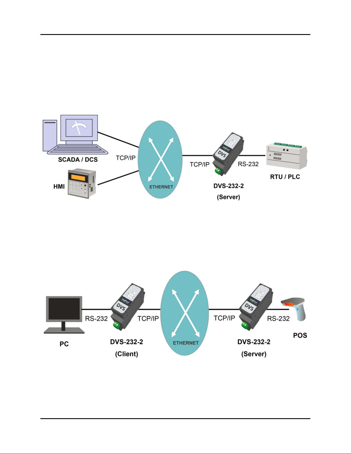
1.4 Typical Applications ........................................................................................................ 5
1.4.1 Device Server..............................................................................................................................................6
1.4.2 Serial over Ethernet.....................................................................................................................................6
1.4.3 Modbus Gateway ........................................................................................................................................7
1.4.4 Modbus Protocol Converter ........................................................................................................................7
1.4.5 Converting RS-232 Network into TCP/IP...................................................................................................8
1.4.6 Remote Control and Monitor ......................................................................................................................9
2.0 SETTING UP THE DEVICE SERVER ................................................................................. 10
2.1 AT Commands (optional) ........................................................................................... 10
2.2 Web Management........................................................................................................... 11
3.0 WEB MANAGEMENT ................................................................................................................ 12
3.1 Logging On.......................................................................................................................... 12
3.2 Current Status .................................................................................................................. 12
3.3 Local IP Settings ............................................................................................................. 13
3.4 Serial Port Settings........................................................................................................ 14
3.4.1 COM Port Settings ....................................................................................................................................14
3.4.2 Operating Mode ........................................................................................................................................15
3.4.3 Reset..........................................................................................................................................................21
3.4.4 Link ...........................................................................................................................................................21
3.4.5 Index .........................................................................................................................................................21
3.4.6 RFC2217 ...................................................................................................................................................22
3.5 Advanced Settings ......................................................................................................... 24
3.5.1 Modbus RTU to Modbus TCP ..................................................................................................................24
3.5.2 Heartbeat Packet .......................................................................................................................................24
3.5.3 Registry Packet .........................................................................................................................................25
3.5.4 Short Connection.......................................................................................................................................26
3.5.5 Disable Old Connections (TCP Server) ....................................................................................................26
3.5.6 Clear Cached Serial Data upon TCP/IP Connection .................................................................................27
3.5.7 Allow Settings via Serial Port ...................................................................................................................27
3.6 Preferences............................................................................................................................. 27
3.6.1 Device Name and Web Server Port...........................................................................................................27
3.6.2 User Name and Password..........................................................................................................................28
3.6.3 Maximum Number of Client Connections ................................................................................................28
3.6.4 Auto-Restart Timeout................................................................................................................................29
4.0 TROUBLESHOOTING .......................................................................................................... 30

CommFront User Manual 2
4.1 Software Tools ...................................................................................................................... 30
4.1.1 The 232Analyzer Protocol Analyzer Software..........................................................................................30
4.1.2 The Serial-TCP software...........................................................................................................................30
4.2 Self Tests.................................................................................................................................. 31
4.2.1 Connecting the Power and Host PC ..........................................................................................................31
4.2.2 Ping Test ...................................................................................................................................................32
4.2.3 Setting up a device server with AT Commands ........................................................................................33
4.2.4 Setting Up Device Sever with Web Management Tools...........................................................................34
4.2.5 Test with the Serial-TCP software ............................................................................................................36
4.2.6 Test with the 232Analyzer software..........................................................................................................37
Appendix: AT COMMANDS SET ................................................................................................. 39
1. Introduction .............................................................................................................................. 39
2. Syntax ........................................................................................................................................... 39
Command syntax................................................................................................................................................39
Response syntax.................................................................................................................................................39
3. Software Tools and Examples ........................................................................................ 40
4. AT Commands Set.................................................................................................................. 41

1.0 Introduction
CommFront User Manual 3
1.0 INTRODUCTION
The DVS-232-2 is a compact, rugged, industrial-grade RS-232 device server that supports
one channel bi-directional RS-232 to Ethernet conversion which can be used to transmit
serial data over Ethernet and TCP/IP network. The applications of the DVS-232-2 include
acting as an RS-232 to Ethernet converter or a Modbus RTU to Modbus TCP protocol
converter; controlling RS-232 serial devices from remote Modbus TCP software or Modbus
RTU master via Ethernet network; making a wide variety of M2M communication
applications possible by enabling client access independent of any operating system or
proprietary protocol; extending RS-232 serial communication distance over Ethernet
network; and converting conventional serial data network to TCP/IP network. The DVS-
232-2 was designed for harsh industrial environments and withstands a wide temperature
range of -40ºF to 185ºF (-40ºC to 85ºC) and is equipped with 15kV ESD and 600W surge
protection. The unit supports TCP and UDP for both server and client modes, and it
features static IP and DHCP for minimizing configuration errors caused by manual entries.
The DVS-232-2 features auto-negotiation for 10 or 100M data rates, and it also supports
MDI and MDI-X (auto-crossover); no DIP switch or jumper settings are required.
1.1 Features
−Compact, rugged, industrial-grade RS-232 device server
−RS-232 to Ethernet converter
−Modbus RTU to Modbus TCP protocol converter
−Modbus gateway for master and slaves
−Designed for harsh industrial environments
−Direct 35mm DIN-Rail mounting
−Easy configuration via AT commands (RS-232) or built-in web server
−Supports static IP and DHCP
−Supports TCP and UDP for both server and client modes
−Supports Httpd client mode
−Supports serial baud rates from 600 bps to 460 Kbps; RFC2217 compliant
−Supports up to 8 simultaneous client connections
−Supports auto-connection (TCP client mode) and auto-restart for smooth operation
−Supports short-connection, index, and other advanced features
−Supports MAC address and user-defined registry packets
−Supports heartbeat packets for maintaining effective network connections
−Auto-negotiation for 10/100M data rates; MDI and MDI-X auto-crossover
−15kV ESD and 600W surge protection
−Operating temperature: -40ºF to 185ºF (-40ºC to 85ºC)
−Compliance: CE, FCC
−Surface Mount Technology manufactured to RoHS and ISO-9001 standards
−5-year manufacturer’s warranty

1.0 Introduction
CommFront User Manual 4
1.2 Factory Settings
IP Settings:
Static IP
IP Address:
192.168.1.200
Subnet Mask:
255.255.255.0
Gateway:
192.168.1.254
DNS:
8.8.8.8
COM Port Settings:
115.2Kbps, 8, N, 1
Local Port:
502
Remote IP:
192.168.1.211
Remote Port:
20000
Modbus:
Modbus RTU <-> Modbus TCP (OFF)
User Name:
admin
Password:
superuser
Note: To restore factory settings, press the “reset” button for 5 to 15 seconds.
1.3 Hardware
1.3.1 Specifications
Compatibility:
EIA/TIA RS-232C; IEEE802.3
Power Source:
5 to 36 VDC
Power Consumption:
Less than 1W
Configuration:
AT commands (RS-232) or built-in web server
Ethernet Network:
10/100M Auto-Negotiation; MDI-X auto-crossover
Network Protocols:
IPv4; TCP/UDP/HTTP; ARP; ICMP
Network Buffer Size:
TX: 6KB; RX: 4KB
IP Settings:
Static IP or DHCP
Operating Modes:
TCP Server & Client; UDP Server & Client; Httpd
Client
Max. No. of Client Connections:
8
Serial Port:
600 bps to 460 Kbps; RFC 2217 compliant
Serial Port Buffer Size:
RX: 2KB
Communication Protocols:
RS-232C; Modbus RTU; Modbus TCP
Protection:
Up to 15kV ESD; 600W Surge Protection
Distance (Ethernet):
328ft (100m)
Distance (RS-232):
16ft (5m)
Connectors (Ethernet):
1x RJ45
Connectors (RS-232):
1x 3-Way Terminal Block (TX, RX, GND)
Connectors (Power):
2-way terminal block
Dimensions (L x W x H):
4.3x1.1x2.6 in (110x28x65 mm)
Weight:
0.2 lb (90 g)
Operating Temperature:
-40ºF to 185ºF (-40ºC to 85ºC)
Operating Humidity:
5% to 95% Non-condensing

1.0 Introduction
CommFront User Manual 5
1.3.2 Connections
FIGURE 1: DVS-232-2 CONNECTION DIAGRAM
1.3.3 LED Indicators
PWR Indicator
ON: Power supply is on
OFF: Power supply is off
ACT Indicator
Flashing: The unit is in working condition
OFF: The unit is not working
TX Indicator
Flashing: Serial port is transmitting data
OFF: Serial port is idle
RX Indicator
Flashing: Serial port is receiving data
OFF: Serial port is idle
10/100M Indicator
ON: The unit is connected to a
100M network
OFF: The unit is connected to a
10M network or is disconnected
Link/Act Indicator
Flashing: Sending/receiving data
OFF: No network connection
1.4 Typical Applications
CommFront device servers are designed for harsh industrial applications and provide
a simple yet reliable solution for the following applications:
−M2M
−IIoT
−Data Acquisition
−Mass Transit
−Point of Sale
−Traffic Signals
−Security Systems
−Energy Plants
−Water and Sewage
−Medical Applications
−Factory/Industrial/Building Automation

1.0 Introduction
CommFront User Manual 6
1.4.1 Device Server
The device server makes a wide variety of M2M communication applications possible
by enabling client access independent of any operating system or proprietary
protocol. In addition, because conventional serial protocol are converted into TCP/IP
protocol, the device server can be accessed by remote TCP/IP software and/or control
stations. This makes the remote control, management, monitoring, and diagnose
possible and, in turn, adds an unprecedented level of intelligence and efficiency to
the operation.
APPLICATION 1: DEVICE SERVER
1.4.2 Serial over Ethernet
The DVS-232-2 supports one channel bi-directional RS-232 to Ethernet conversion
which can be used to transmit serial data over Ethernet and TCP/IP network. “Serial
over Ethernet” allows you to make use of an existing Ethernet network and extend
the distance across a facility or to other facilities all over the globe.
APPLICATION 2: SERIAL OVER ETHERNET

1.0 Introduction
CommFront User Manual 7
1.4.3 Modbus Gateway
Modbus RTU is the most widely used industrial protocol. A typical Modbus system
consists of one master and multiple slaves that run over the same single twisted pair
cable. The DVS-232-2 can act as a Modbus gateway that encapsulates Modbus
packets in standard TCP/IP packets. This enables the filed Modbus devices to connect
and communicate over existing Ethernet and fiber networks instantly. In addition,
conventional Modbus RTU has a limitation of 247 nodes per network, while Modbus
TCP networks can have as many slaves as the physical layer can handle, which often
go around 1,024.
APPLICATION 3: MODBUS GATEWAY
1.4.4 Modbus Protocol Converter
The DVS-232-2 can act as a Modbus protocol converter that encapsulates Modbus
packets in standard TCP/IP packets. A Modbus protocol converter allows conventional
Modbus RTU master and slave devices that run on twisted-pair cable to run over
Ethernet and fiber networks with greater distance and flexibility (e.g. the COM port
settings for client and server can be different).
APPLICATION 4: MODBUS PROTOCOL CONVERTER

1.0 Introduction
CommFront User Manual 8
1.4.5 Converting RS-232 Network into TCP/IP
By using device servers, you can convert existing RS-232/RS-485 field devices such
as PLC and RTU into TCP/IP devices, which can directly be controlled by the TCP/IP
control software. With CommFront’s Serial-TCP software (an advanced serial to
TCP/IP bridging software), you can also convert conventional serial control software
into TCP/IP software instantly and seamlessly without a need of software
modifications. In addition, various serial devices with different COM settings
(RFC2217 supported) can be merged into the same TCP/IP network, thus making the
entire network conversion fast, easy, and secure.
APPLICATION 5-1: CONVERTING RS-232 NETWORK INTO TCP/IP (SERIAL-TCP)
APPLICATION 5-2: CONVERTING RS-232 NETWORK INTO TCP/IP (DVS-232-2)

1.0 Introduction
CommFront User Manual 9
1.4.6 Remote Control and Monitor
From award-winning 232Analyzer Protocol Analyzer to Advanced Serial to TCP/IP
Bridging Software, and from industrial Serial Converters, Isolators, Repeaters, and
Hubs to the compact Device Servers, CommFront offers a complete hardware and
software solution for controlling and monitoring conventional serial and modern
TCP/IP communications. In addition, not only you can test, debug, control, and
monitor serial and TCP/IP communications including Modbus RTU/ASCII and Modbus
TCP, but you can also integrate our industry-proven software and hardware products
with your mission-critical projects without a need of software or hardware
modifications.
1) Via COM port: In TCP server mode, the device server can turn on the “Index”
feature so to see the data source on the 232Analyzer software (see “Index”
feature for more information).
2) Via TCP/IP: When working together with the Serial-TCP software via a pair of
virtual COM ports, the conventional serial control software such as the
232Analyzer software can be turned into a TCP/IP control software instantly and
seamlessly without a need of software or hardware modification. In addition, with
the Serial-TCP software’s built-in “debugging” feature, all data between serial port
and TCP/UDP port can be monitored and logged.
APPLICATION 6: REMOTE CONTROL AND MONITOR

2.0 Setting Up the Device Server
CommFront User Manual 10
2.0 SETTING UP THE DEVICE SERVER
The DVS-232-2 offers two easy ways for configuration: AT commands via COM port
or Web Management via the built-in web server (see “Web Management”).
2.1 AT Commands (optional)
Assume that your PC is at the same sub network of “172.16.0.x”.
Note: Skip this step and go directly to “Web Management” if your PC is at the same
sub network of “192.168.1.x”.
1) Download and install the free version of CommFront’s 232Analyzer software
(download link: https://www.commfront.com/pages/downloads).
2) Run the 232Analyzer software and set COM port settings to 115.2Kbps, 8, N,
1. Then select “ASCII” for both TX and RX data formats.
3) To enter AT Command mode, first send the ASCII code: +++
4) The DVS-232-2 responds with an ASCII code: a
5) Send the second ASCII code within 3 seconds: a
6) The DVS-232-2 responds with an ASCII code and it now enters into “AT
Command” mode: +ok
7) Query current network settings: AT+WANN<CR>
Note: <CR> equals to “D” in Hex code, remember to enter “D,” into the
second box below
8) The DVS-232-2 responds with the current network settings:
<CR><LF>+OK=STATIC,192.168.1.200,255.255.255.0,192.168.1.25
4<CR><LF>

2.0 Setting Up the Device Server
CommFront User Manual 11
9) Change network settings to the same sub network as your PC, e.g.:
AT+WANN=STATIC,172.16.0.100,255.255.255.0,172.16.0.1
<CR>
10) The DVS-232-2 responds with a confirmation code: +ok
11) Restart the DVS-232-2 for the new settings to take effect: AT+Z<CR>
12) The DVS-232-2 is now at the same sub network of your PC. Proceed to web
management for further configurations (see “Web Management”).
Note: For more detailed information about AT Commands, please refer to Appendix:
AT Commands Set.
2.2 Web Management
Web management offers a user-friendly interface for fast and easy configuration. All
parameters and functions can be set from the web management tools. You can go
directly to web management tools if your PC is at the same sub network of
“192.168.1.x”. Consult with your network administrator on how to change your PC’s
network settings, if necessary.

3.0 Web Management
CommFront User Manual 12
3.0 WEB MANAGEMENT
Web management offers a user-friendly interface for fast and easy configuration. All
parameters and functions can be set from web management. The default IP address
of web management is: 192.168.1.200. You can go directly to web management if
your PC is at the same sub network of “192.168.1.x”. Consult with your network
administrator on how to change your PC’s network settings, if necessary.
3.1 Logging On
A user name and password is required to log onto web interface.
-default user name: admin
-default password: superuser
Note: User name and password can be changed under the “Preferences” web page.
3.2 Current Status
The “Current Status” web management page gives you a brief view of the current
status of the device including MAC address, the current IP address, and the current
remote connections as well as the number of bytes sent and received.
Note: For server mode, the number of remote TCP connections are indexed and can
be used for identifying the source of TCP packets (see “Index” feature).

3.0 Web Management
CommFront User Manual 13
3.3 Local IP Settings
The “Local IP” web management page allows you to set the following parameters:
-IP Address Type: Static IP or DHCP
-DNS type (for DHCP): Auto or Manual
-Static IP Address
-Subnet Mask
-Gateway
-DNS Server
Table 1: Default Local IP settings
IP Settings:
Static IP
DNS Type (for DHCP):
Auto
IP Address:
192.168.1.200
Subnet Mask:
255.255.255.0
Gateway:
192.168.1.254
DNS Server
8.8.8.8
Notes:
-Remote IP Address and Port Mapping are to be set at “Serial Port” web page.
-Please consult with your network administrator for IP and Port settings, if
necessary.

3.0 Web Management
CommFront User Manual 14
3.4 Serial Port Settings
The “Serial Port” web management page allows you to set the COM port parameters,
local port number, the remote server’s IP address and port number for which this
device is connected to, the operating mode (e.g. TCP client or TCP server), and other
features including reset, link, index, and RFC2217.
Table 2: Default COM Port and IP Port settings
Baud Rate:
115.2Kbps
Data Bit:
8
Parity:
None
Stop Bit:
1
Local IP:
192.168.1.200 (refer to Local IP settings)
Local Port:
502
Remote IP:
192.168.1.211
Remote Port:
20,000
Operating Mode:
TCP Client
3.4.1 COM Port Settings
The COM port settings must match with the RS-232 device to which the DVS-232-2
is connected, COM port settings include the following parameters:
-Baud Rate: 600bps to 460.8Kbps
-Data Bit: 7 or 8
-Parity: None, Odd, Even, Mark, Space
-Stop Bit: 1 or 2

3.0 Web Management
CommFront User Manual 15
3.4.2 Operating Mode
CommFront’s device servers offer three types of network connections: TCP socket,
UDP socket, and HTTP web socket.
TCP is a connection-oriented protocol that provides reliable, ordered and error-
checked delivery for network packets. For such reasons, TCP is recommended for
device servers because mission-critical messages are transmitted over a crowded
Ethernet network. Under TCP operating mode, device servers must first establish a
client-server network connection prior to transmitting serial data over a TCP/IP
network. Up to 8 clients can co-exist and communicate with the server concurrently;
however, only one server can exist in a client-server network connection.
UDP is a datagram-oriented (connectionless) protocol that is used for broadcast and
multicast network transmission. UDP works similar to TCP, and it also checks for data
integrity at the arrival time. However, UDP protocol has no fixed order, and it discards
erroneous packets.
HTTPD (or HTTP) is an application-layer protocol for transmitting web contents or
data between web server and the clients. HTTPD follows a classical client-server
model, which means requests are initiated by the client, usually a web browser.
There are a total of five operating modes in CommFront’s device servers.

3.0 Web Management
CommFront User Manual 16
1) TCP Client:
Under TCP client mode, the DVS-232-2 automatically initiates a TCP network
connection request to the remote server. If the connection is successful,
client’s IP address will be displayed under server’s “current status”, and if the
connection is unsuccessful, the DVS-232-2 will keep on sending connection
requests until it is successful. Once connected, TCP client can start to forward
/ receive serial data to / from server’s serial port. TCP client can choose to
send heartbeat (or keep-alive) packets to remote server for maintaining the
network connections (see “Heartbeat Packets” for more information).
-Remote IP: Enter remote TCP server’s IP address
-Remote Port: Enter remote TCP server’s port number
-Local IP: (To be set under “Local IP”)
-Local Port: Enter local port number, if the number is 0, the device will
use random number for connecting to remote server.
Note: Upon TCP connection, serial data received on client’s COM port will be
forwarded to remote server only. Other clients will not receive the same serial
data.

3.0 Web Management
CommFront User Manual 17
2) TCP Server:
Under TCP server mode, the DVS-232-2 will monitor its local port and establish
connections whenever there is a new TCP connection request. TCP server
allows a maximum of 8 client connections concurrently. If the number of client
connections exceed 8, you can set to disable or keep the old TCP connections
(see “Disable Old Connections” for more information).
-Local IP: (To be set under “Local IP”)
-Local Port: Enter local port number for the server. 0 is not allowed.
Note: Upon TCP connection, serial data received on the server’s COM port will
be forwarded to ALL clients.

3.0 Web Management
CommFront User Manual 18
3) UDP Client:
UDP is a connectionless protocol and does not require a network connection
like TCP prior to transmitting serial data over Ethernet. A UDP client can start
to forward serial data to the UDP server’s serial port as soon as the server’s IP
address and port number are defined and matched.
-Remote IP: Enter remote UDP server’s IP address
-Remote Port: Enter remote UDP server’s port number
-Local IP: (To be set under “Local IP”)
-Local Port: Enter local port number. If the number is 0, the device will use a
random number.
Note: Serial data received on the UDP client’s COM port will be forwarded to
remote UDP server only. Other clients will not receive the same serial data.

3.0 Web Management
CommFront User Manual 19
4) UDP Server:
Unlike a TCP server, which forwards its serial data to all connected clients, a
UDP server forwards serial data only to the source (IP + port) of last-received
data. For example, if the UDP server receives data from Client A first and then
from Client B, its serial data will be forwarded to Client B only. (Client A will
not receive any data from the UDP server).
-Local IP: (To be set under “Local IP”)
-Local Port: Enter local port number for the server. 0 is not allowed.
Note: UDP server does not have any destination IP and port to forward its
serial data and therefore, communications must be initiated from UDP client.
Other manuals for DVS-232-2
1
Table of contents
Popular Industrial Equipment manuals by other brands

Feina
Feina SF70-1EH quick start guide

Aerotech
Aerotech HIGH-POWER RMS M750W-P Assembly and operation instructions

VIA Technologies
VIA Technologies WorkX Connect quick start guide

YOKOGAWA
YOKOGAWA ISC40PR instruction manual

Beckhoff
Beckhoff EP3356-0022 Documentation

Sharp
Sharp MAX-PRO 1182 Operator's manual