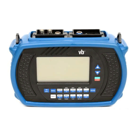
Commtest Instruments vbBalancer User manual

Instrument Reference
Guide
Revision
May 19
th
2008
vbBalancer™ and vbBalancer+™
Imbalance Correction Instruments

ii
COPYRIGHT © 2008 Commtest Instruments Ltd.
All rights reserved. No part of this document may be reproduced,
stored in a retrieval system or transmitted in any form or by any
means electronic, mechanical, photocopy, recording or otherwise
without the prior written permission of Commtest Instruments Ltd.
For information, contact:
Commtest Instruments Ltd
28B Moorhouse Avenue
Christchurch
New Zealand
E-mail help@commtest.com
Printed in New Zealand.
Disclaimer
The information contained in this document is subject to change
without notice. Names and data used in examples are fictitious
unless otherwise noted. This document is distributed as is, without
warranty of any kind, either expressed or implied, respecting the
information supplied, including but not limited to implied warranties
for the document’s quality, performance, merchantability, or fitness
for any particular purpose. Neither Commtest Instruments Ltd nor its
employees, dealers, agents or distributors shall be liable to the user
of this document or any other person or entity with respect to any
liability, loss or damage caused or alleged to be caused directly or
indirectly by this document.
Trademark Notice
vb™, vb1000v™, vb1000™, vb2000™, vb3000™, vb5™, vb6™,
vb7™, vb8™, vbBalancer™, vbBalancer+™, 6Pack™,
vbXManager™ and PROFLASH™ are trademarks of Commtest
Instruments Ltd.
vbSeries®, Commtest®,vbOnline® and Ascent®are registered
trademarks of Commtest Instruments Ltd. Other trademarks and
registered trademarks are the property of their respective owners.

iii
Contents
Section 1: Introduction.................................................1
Standard Features ................................................................. 1
Standard Kit Items ................................................................. 2
Instrument Capabilities........................................................... 3
Precautions............................................................................ 5
Hazardous Locations ............................................................. 7
Instrument Connections ......................................................... 9
Front Panel Buttons ............................................................. 10
LED Indicators ..................................................................... 11
Charging the Battery Pack ................................................... 12
Battery Features .................................................................. 12
Removing the Battery Pack.................................................. 13
Operating Overview ............................................................. 14
Balancing ...................................................................................14
Onsite Analysis..........................................................................15
Section 2: Instrument Basics.....................................16
Powering On/Off .................................................................. 16
Navigating Menus ................................................................ 17
Returning to a Previous Menu.............................................. 17
Using Navigation Keys and Icons......................................... 18
Selecting an Option from a List ............................................ 19
Canceling an Option ............................................................ 21
Displaying Hint Labels and Detailed Help ............................ 21
Displaying Alternative Options ............................................. 22
Entering Alphanumeric Characters ...................................... 23
Entering Punctuation, Spaces and Special Characters ........ 25
Using Other Icons ................................................................ 26
Section 3: Using Sensors...........................................28
Supported Sensor Types ..................................................... 28

iv
Connecting Sensors to the Instrument ................................. 29
Mounting Sensors................................................................ 30
Setting up the Accelerometer............................................... 31
Permanent Mounting .................................................................32
Setting up the Tachometer................................................... 32
Tachometer Signal from a Keyphasor® ............................... 34
Section 4: Balancing Rotors ......................................35
Methods for Balancing Rotors.............................................. 35
The Balancing Process ........................................................ 36
Tips for Balancing ................................................................ 37
The Tachometer .................................................................. 37
Suggested Trial Weight Mass and Location ......................... 38
Manually Entering Balancing Information ............................. 38
Setting up a Balancing Job .................................................. 39
Balance Planes and Weight Positions.......................................40
Balance Planes....................................................................40
Weight Position (Reference Mark) ...................................... 40
# Sensors...................................................................................41
CH Position..........................................................................42
Averages....................................................................................44
Machine Information ..................................................................44
Rotor Weight, Diameter and Speed ....................................44
Reference Mark ................................................................... 44
Weight Orientation.....................................................................45
Tach Trigger ..............................................................................45
Weight Lin Dist ..........................................................................45
Store Units.................................................................................46
Combining Trim Weights...................................................... 46
Reviewing Previous Balancing Jobs..................................... 47
Section 5: Balancing Walk-through...........................49
Step 1. Set Up a New Balance Job ...................................... 49
Step 2. Take an Initial Reading ............................................ 50
Step 3. Take a Trial Reading ............................................... 51
Step 4. Balance the Rotor .................................................... 54
Step 5. Perform Trim Balancing ........................................... 55

v
Step 6. Viewing and Saving Balancing Jobs ........................ 57
Section 6: Analyzing Measurements Onsite.............58
Tips for Taking Measurements............................................. 58
Walk-through: Taking Measurements................................... 59
Working with Charts............................................................. 62
Analyzing Measurements..................................................... 62
Using Cursors............................................................................63
Zooming.....................................................................................65
Viewing Multiple Charts........................................................ 66
Changing Chart View ........................................................... 66
Setting the Y Axis (Amplitude) Scale.................................... 67
Amplitude Display Units ....................................................... 68
Setting the RPM................................................................... 69
Viewing Orders .................................................................... 70
Viewing Revolutions............................................................. 71
Saving Measurements ......................................................... 71
Section 7: Setting Measurement Options .................73
Setting Measurement Units and Spectrum Scaling .............. 73
Setting Measurement Parameters........................................ 75
Creating Your Own Parameter Sets..................................... 76
Assigning Sensors to Channels ........................................... 77
Explaining Spectrum Parameters......................................... 78
Fmax..........................................................................................78
Spectral Lines............................................................................79
Fmin...........................................................................................79
Tach Trigger ..............................................................................80
Averaging...................................................................................80
Average Overlap..................................................................80
Explaining Waveform Parameters........................................ 80
Equivalent Fmax........................................................................80
Number of Samples...................................................................80
Duration ..................................................................................... 81

vi
Section 8: Measurement Types and Their Uses.......82
Spectrum ............................................................................. 82
Waveform ............................................................................ 83
Tachometer Display ............................................................. 83
Bump Test ........................................................................... 84
Coast-down/Run up ............................................................. 85
Taking Multi-channel Simultaneous Measurements ............. 86
Setting up Sensors and Channels.............................................86
Saving Multi-channel Measurements ........................................87
Section 9: Taking Recordings ...................................89
Walk-through: Taking Recordings ........................................ 89
Taking Individual and Multiple Recordings ........................... 90
Saving Recordings............................................................... 91
Reviewing Recordings ......................................................... 91
Deleting Recordings............................................................. 93
Attaching Notes ................................................................... 93
Section 10: Creating, Editing and Deleting Items ....94
Storage Capacity and Recording Volume ............................ 94
How are Recordings Organized and Stored?....................... 94
Working with Folders ........................................................... 96
Creating a Folder....................................................................... 96
Renaming a Folder ....................................................................96
Deleting a Folder ....................................................................... 96
Restoring a Deleted or Over-Written Folder..............................96
Working with Machines ........................................................ 97
Creating Machine Structures.....................................................97
Creating Parameter Sets ........................................................... 98
Adding Structures to Existing Machines....................................99
Copying Machine Structures ...................................................100
Renaming Machine Structures ................................................100
Deleting Machine Structures ...................................................101
Working with Sensors ........................................................ 101
Defining and Editing Sensors ..................................................101
Using the Bias Voltage Check.................................................103

vii
Deleting Sensors .....................................................................104
Working with Notes ............................................................ 105
Creating Notes.........................................................................105
Editing Notes ...........................................................................105
Attaching Notes .......................................................................105
Viewing Notes..........................................................................106
Removing Notes ......................................................................106
Deleting a Note Permanently...................................................106
Deleting all Recordings in a Folder .................................... 107
Deleting all Stored Information........................................... 107
Section 11: Utilities...................................................108
Setting the Date and Time ................................................. 108
Adjusting the Date Format.......................................................108
Selecting Your Local Timezone.......................................... 109
Adjusting Sound Volume.................................................... 109
Set the Instrument Language............................................. 109
Printing Directly to a Network Printer.................................. 110
Adjusting Screen Contrast ................................................. 111
Turning the Backlight On/Off.............................................. 111
Recharging the Instrument................................................. 112
Estimating Remaining Operating Time............................... 112
Conserving Battery Power ................................................. 112
Setting Backlight Timeout........................................................113
Setting Sleep Mode Timeout ...................................................113
Setting Complete Powerdown Timeout ...................................114
Checking How Much Memory is Available ......................... 114
Freeing Instrument Memory ............................................... 114
Backing Up the Instrument Database................................. 115
Upgrading Instrument Firmware (Proflashing).................... 116
Section 12: Troubleshooting ...................................118
Contacting Technical Support ............................................ 118
Resetting an Unresponsive Instrument .............................. 118
Network Communications Problems .................................. 118
Ethernet Connection Lost in Windows Vista....................... 120

viii
Appendix: Specifications .........................................122
vbBalancer......................................................................... 122
vbBalancer+....................................................................... 124
Index ..........................................................................126

Section 1: Introduction
1
Section 1: Introduction
Please keep this Instrument Reference Guide for future reference
and read it before operating your balancing instrument.
Although this book makes use of common balancing and vibration
analysis concepts, it is not intended as a comprehensive guide or
training manual. Please ensure you have the relevant knowledge
and experience to carry out the procedures described. It is essential
to follow all appropriate safety precautions when working near
rotating machinery.
Product and support feedback
If you any have questions not answered by this reference guide, or
would like to make a suggestion, please contact us at
www.commtest.com.
Standard Features
•Balancing capability: single and dual plane
•Tachometer and Keyphasor® input for speed and phase
measurements
•DSP for fast, accurate calculations
•24-bit A/D converter providing high-precision measurements
•Displacement, velocity and acceleration measurements
•Frequency and time domain measurements
•1 GB non-volatile flash memory providing almost unlimited
recording storage
•Time and date stamped recordings
•vb firmware - upgradeable using Commtest PROFLASH
•Temperature compensated graphical LCD (Liquid Crystal
Display) with 480 x 320 pixels and white LED backlight
•4500 mAh custom Lithium Ion battery pack
•Battery charger
•USB or Ethernet interface for PC communications

Section 1: Introduction
2
Standard Kit Items
•vbBalancer portable imbalance correction instrument
(vbBalancer or vbBalancer+) with carry strap and sensor
bracket
•Power adapter 12 V 3 A output, center positive
•DC car adapter 12 V DC output
•USB data transfer cable
•Accelerometers (IEPE/ICP®-type)*
•Accelerometer coiled cables*
•Accelerometer magnetic mounting bases*
•Triple BNC adapter (vbBalancer+ model only)
•Non-contact laser tachometer sensor
•vbXManager software on CD-ROM
•Instrument Reference Guide
•Warranty card
•QA card
•Carry bag
* Number provided varies according to instrument model.
vbBalancer: 2units, vbBalancer+: 4units.
Balancing kit items
•Reflective tape
•Adjustable tachometer stand with magnetic mount
•Tachometer extension cable (5 meters)
•Accelerometer extension cables (5 meters)+
+Number provided varies according to instrument model.
vbBalancer: 2units, vbBalancer+: 4units.
Note: Thoroughly inspect your instrument kit's contents upon receipt.
If any kit items are missing, please contact Commtest customer
support or your sales agent for assistance.

Section 1: Introduction
3
Instrument Capabilities
vbBalancer instrument capabilities vary according to model variant.
For details of your specific instrument model's capabilities, see the
information listed below.
Measurement Channels (Max)
vbBalancer vbBalancer+
Dual (2) Channel Simultaneous
Four (4) Channel Simultaneous
Balancing Capability
vbBalancer vbBalancer+
Balancing 2 Planes
Balancing 2 Sensors
Balancing 4 Sensors

Section 1: Introduction
4
Measurement Capabilities
vbBalancer vbBalancer+
Spectrum/Waveform
Bump Test
Coast-down/Run-up
Sensor Output Accepted
vbBalancer vbBalancer+
Acceleration
Velocity
Displacement

Section 1: Introduction
5
Precautions
Please read and understand this section before operating your
instrument. Heed all warnings and recommendations to prevent data
loss, data inaccuracy, damage to the instrument, or injury to yourself.
Do not attach sensors to any object with a high
potential voltage i.e. a voltage that exceeds 50 V DC or
32 V AC or the ‘safety extra low voltage’ (SELV)
defined by your local power authority.
Ensure the cables and bootstrap cannot become
entangled with any rotating or moving machinery.
Do not bring any objects sensitive to magnetic fields
near the magnetic mounting bases (e.g. cardiac
pacemakers, credit cards, floppy disks, video tapes,
audio cassette tapes, mechanical watches).
Do not operate the instrument in an explosive
environment.
Do not detach the battery pack from the instrument for
more than 10 minutes. This will cause the instrument's
date/time to be lost. The instrument will retain all
recordings and other information.
Neck-straps must be connected to the instrument via
the 2.5 turn stainless steel rings provided. The strap
must not be connected directly to the unit as this will
defeat the 10 kg safety release provided by the rings.
Replacement rings are available from Commtest.

Section 1: Introduction
6
Use only an approved power adapter 12 V 3 A output,
center positive. Do not use the plug-pack transformers
supplied with previous Commtest instrument versions
(such as the vb1000-3000 and Profiler) as these
transformers will be damaged.
The cover over the comms and charger connectors
provides an essential seal. It must be in place
whenever using the instrument in an industrial
environment.
Ensure that the drive current is turned on when using
an IEPE/ICP®-type accelerometer, otherwise the
measurements will be incorrect.
Mount the sensor properly before taking measurements
to ensure their accuracy and consistency.
Use a mild detergent diluted in warm water to clean the
instrument. Do not use abrasive or polishing
substances, hydrocarbons, petrochemicals or solvents,
as they will degrade the plastic casing.
Do not place the instrument or the magnetic mounting
base anywhere that the temperature might exceed 140
°F (60 °C). This will degrade the battery pack and
magnet.
If the instrument malfunctions, return it to an authorized
dealer. Do not attempt to repair the instrument yourself
as this will void your warranty.

Section 1: Introduction
7
Hazardous Locations
Selected models of the vbBalancer range have been approved by
the Canadian Standards Association (CSA) for use in hazardous
locations meeting this classification: Class I, Division 2, Groups A, B,
C, D.
Those models are clearly identified with the CSA logo and a
Hazardous Location information panel. Models without those
markings are NOT approved for operation in hazardous locations.
The Class I Div 2 classification is officially defined in the Canadian
Electrical Code part 1, but can be summarized as:
A location in which volatile flammable gases or vapors are present
but confined within closed systems from which they can escape only
in case of accidental rupture or abnormal operation; or in which
ignitable concentrations of gases are normally prevented by positive
pressure or mechanical ventilation, and which might become
hazardous through abnormal operation of the ventilation equipment.
The approval specifically covers use in the United States of America
and also any other countries which recognize the CSA certification.
When using a certified vbBalancer in a hazardous location, the
installation must comply with the vbX Installation Control Drawing for
Hazardous Locations, including all its foot-notes and warnings. This
drawing, number CIL2100VBX, is inserted on the following page.
The vbBalancer instrument will be supplied complete with
appropriate sensors for use in Class I Div 2 environments. As
indicated on the drawing, alternative sensors may be used, provided
they are certified for use in these locations and their entity
parameters meet the limits shown on the drawing.

Section 1: Introduction
8

Section 1: Introduction
9
Instrument Connections
The top panel of the instrument is equipped with the following
connection interfaces.
1. Ethernet port. Connects to a standard 8P8C ('RJ45') male plug
terminator
2. Charger power socket (12 Volt 3 Amp input). This may be used to
power the instrument and/or to charge the instrument's battery pack
3. USB socket. Provides a data connection between the instrument
and the vbXManager software's host computer
4. BNC sensor input (Channel 1)
5. BNC sensor input (Channel 2) OR LEMO seven-pin input*
(Channels 2 to 4)
6. LEMO four-pin tachometer input
* This feature is only available on the vbBalancer+ instrument model
Note: The comms and charger area's protective rubber gasket
should be kept closed and in place when collecting data in the field.
Doing so will help maintain the environmental sealing of the
instrument case.

Section 1: Introduction
10
Front Panel Buttons
Instrument Front Panel
Turn the instrument On/Off.
Cancel/Go Back. A long press takes you back to the Main
Menu.
Accept/Go forward to the next menu.
Activate alternate functions for each key. In some menus
the keys can perform several functions; to see what
options are available press ALT to toggle the key
functions.
Help key: expand on-screen icons with easy to see hint
labels. A long press displays detailed help text.
Navigate up/down through a list. To move more rapidly
through a list, press and hold.
Navigate left/right. Also expands and collapses levels in
the navigator and directs movement between split-screen
menus e.g. the Review Vibration Menu.

Section 1: Introduction
11
LED Indicators
Five LED indicators located on the instrument's front panel indicate
the instrument's current state and warn of measurement problems.
Instrument LEDs
Power supply (GREEN)
Illuminates when power is supplied to the
instrument from the power adapter.
Charging (RED)
Indicates that the instrument battery is
charging.
Danger (RED)
Illuminates when a DSP or critical error
occurs.
Alert (AMBER) Not used on vbBalancer instruments
models.
OK (GREEN)
Indicates that a measurement is being, or
has been, collected su
ccessfully (without an
error or alert triggered).

Section 1: Introduction
12
Charging the Battery Pack
Warning: Before charging the battery pack, ensure that the power
transformer used is an approved power adapter 12 V 3 A output,
center positive. Do not use the plug-pack transformers supplied with
previous Commtest portable analyzers such as the vb1000-3000 or
Profiler instruments.
The power adapter supplied in the kit provides the correct DC
voltage.
•Connect the AC power adapter included with the instrument
to a powered outlet (100-240 Volt, 50/60 Hz).
Note: The optional car adapter charging lead may also be used to
charge the battery pack in a vehicle with a 12 V negative-chassis
power system.
•Connect the adapter's DC output to the instrument's charger
power socket. The instrument's Power supply and
Charging LED indicators will illuminate indicating a charging
state.
Notes:
A full battery charge will complete in approximately 3 hours.
The fast-charge Lithium Ion-type battery pack should be charged for
a minimum of 1 hour before or during its initial use.
Battery Features
The instrument is powered by a rechargeable custom Lithium Ion
battery pack with a normal operating range of 6.5 V to 8.4 V.
The instrument is equipped with an internal backup component that
protects data and settings in case the battery pack is momentarily
removed from the instrument. The backup component is kept
charged by the battery pack if the battery pack is functioning
normally. The instrument has a number of inbuilt features which help
ensure that the battery pack is always sufficiently charged.
This manual suits for next models
1
Table of contents
Other Commtest Instruments Measuring Instrument manuals