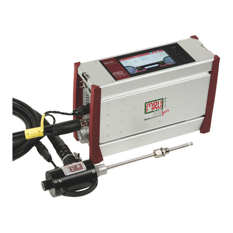
mru SYNGAS VARIOluxx User manual

9442EN
VARIOluxx SYNGAS
USER MANUAL

User Manual VARIOluxx Syngas
2 / 118 MRU GmbH, D-74172 Neckarsulm
Manufacturer:
Legal notices / Intellectual property rights comments
Original user manual
© 2022 by MRU
No part of this manual my be published in any form (print, photocopy, electronic media or
any other publication form) without a written approval by the publisher.
All user trade marks and name mark descriptions, even those which are not marked as such,
are properties of the respective owners.
Edition: 2022-08-30, V4.20.EN

User Manual VARIOluxx Syngas
MRU GmbH, D-74172 Neckarsulm 3 / 118
Note on electrochemical sensors
Electrochemical sensors are by their operating principle not only sensitive to
the gas they are intended for, but for other gases as well.
This cross sensitivity is compensated by MRU for the typical application of flue
gas analysis.
However, unusual high concentration levels of single gas components might
lead to
•a reduced measurement accuracy of other gas components
•and to a temporary change of the sensitivity of sensors, which may re-
quire several hours recovery time.
Especially concentration levels as high as several % for single gas components
may affect the measurement of other gas components at ppm level. Those
applications need to be discussed with MRU in detail.

User Manual VARIOluxx Syngas
4 / 118 MRU GmbH, D-74172 Neckarsulm
Table of content
1Information for product and safety........................................................8
1.1. Safety manual .......................................................................................................8
1.2. Safety precautions...............................................................................................8
2Introduction .............................................................................................9
2.1. Intended use .........................................................................................................9
2.2. About us ...............................................................................................................10
3Description ............................................................................................ 11
3.1. Task.........................................................................................................................11
3.2. Gas flow diagram...............................................................................................11
3.3. The Analyser........................................................................................................12
3.4. Connectors...........................................................................................................13
3.5. Probes....................................................................................................................14
3.6. Heated Gas sampling probe ..........................................................................15
3.7. Unheated Gas sampling probe.....................................................................16
3.8. Gas conditioning................................................................................................17
3.9. Gas supply............................................................................................................17
3.10. Gas sensors ..........................................................................................................17
4Operation............................................................................................... 18
4.1. Commissioning ..................................................................................................18
4.2. Operating panel.................................................................................................18
4.3. Charging the battery........................................................................................19
4.4. Switching on the analyser ..............................................................................19
4.5. Switching off the analyser ..............................................................................20
4.6. Turn Display.........................................................................................................20
4.7. Set the analyser to standby mode ...............................................................21
4.8. Back to homescreen / Back to measure .....................................................22
4.9. Create screenshots............................................................................................22
5Settings.................................................................................................. 23
5.1. Open menu Settings.........................................................................................23
5.2. General settings .................................................................................................23
5.3. Setting Date and Time .....................................................................................24
5.4. Device settings ...................................................................................................25
5.5. Water monitoring..............................................................................................27
5.6. Averaging.............................................................................................................30
5.7. Interval measurement......................................................................................32
5.8. Programs ..............................................................................................................36
5.9. Analog output setup (4-20mA).....................................................................37
Setting channel ............................................................................................................ 37
Setting lower / higher limit ...................................................................................... 38
Setting Analog outputs during zeroing............................................................... 39
Pin assignment of the 4-20 mA interface (Analog IN/OUT)........................... 39
5.10. Analog input setup (4-20mA)........................................................................40
5.11. Connecting analyser with WIFI (WLAN) .....................................................41
5.12. Getting information about the network....................................................43
5.13. Assigning a fixed IP address...........................................................................43

User Manual VARIOluxx Syngas
MRU GmbH, D-74172 Neckarsulm 5 / 118
5.14. Serial connectivity (RS485/USB) ...................................................................44
5.15. Default settings..................................................................................................46
5.16. Configuration of measurement program..................................................47
Test program................................................................................................................. 47
Measurement program.............................................................................................. 47
Further measuring programs .................................................................................. 47
Moving a value field.................................................................................................... 47
Assign a measured value........................................................................................... 47
Setting zoom................................................................................................................. 48
6Measurement ........................................................................................ 49
6.1. Preparing measurement .................................................................................49
Setting up the measuring point ............................................................................. 49
Operating temperature ............................................................................................. 50
Power supply................................................................................................................. 50
Switch-on, warm-up phase, zero point................................................................ 50
Repeated Zero point................................................................................................... 51
Automatic zero point ................................................................................................. 51
Use last valid zero point ............................................................................................ 52
Select Source zero point (gas)................................................................................. 53
Charging state of the battery .................................................................................. 54
Connections to the analyser .................................................................................... 54
Attach clip-on filter ..................................................................................................... 55
Controlling Filters........................................................................................................ 55
6.2. Take a measurement........................................................................................56
Setting O2 reference and Fuel type....................................................................... 56
Setting CO purge limit ............................................................................................... 56
Starting the measurement ....................................................................................... 57
Storing measured values........................................................................................... 57
Select channels for graphic display....................................................................... 58
Starting Auto-measurement.................................................................................... 60
Stopping Auto-measurement ................................................................................. 62
7Data memory......................................................................................... 63
7.1. Organizing data memory................................................................................63
7.2. Managing sites ...................................................................................................63
Adding a new site........................................................................................................ 63
Changing site data ...................................................................................................... 64
Deleting sites................................................................................................................. 65
Recalling stored measurements ............................................................................. 66
Delete stored measurements .................................................................................. 66
7.3. Data transfer via USB (CSV export) ..............................................................68
8Extras ..................................................................................................... 71
8.1. Open menu Extras.............................................................................................71
8.2. History ...................................................................................................................71
8.3. System extensions.............................................................................................73
8.4. Connections ........................................................................................................74
User Manual VARIOluxx Syngas
6 / 118 MRU GmbH, D-74172 Neckarsulm
8.5. Automatic device start.....................................................................................74
8.6. Instrument leak test..........................................................................................75
8.7. Printing measurement results.......................................................................77
Printing current measurement results.................................................................. 77
Printing stored measurement results ................................................................... 78
9Service.................................................................................................... 80
9.1. Open menu Service...........................................................................................80
9.2. Service values......................................................................................................80
9.3. Performing Device selftest .............................................................................81
9.4. Internal log settings..........................................................................................82
Copying all log data.................................................................................................... 82
Copying single log data............................................................................................. 83
Export NDIR – Factors................................................................................................. 85
10 Info...................................................................................................... 86
10.1. Open menu Info.................................................................................................86
10.2. Calling up device info.......................................................................................86
10.3. Device usage.......................................................................................................88
11 Maintenance and cleaning ............................................................... 89
11.1. Cleaning and maintenance............................................................................89
11.2. Service check.......................................................................................................89
12 Simple service work .......................................................................... 90
12.1. Information of the analyser components..................................................90
12.2. Updating the firmware ....................................................................................90
Update main firmware ............................................................................................... 90
Update firmware of single modules...................................................................... 94
13 Specifications..................................................................................... 96
13.1. General data........................................................................................................96
13.2. Gas sampling and conditioning ...................................................................97
13.3. Sensors for gas concentration, temperature and pressure.................97
13.4. Specifications of NDIR technology ..............................................................98
13.5. Calculated values and accessories...............................................................99
13.6. Data communication........................................................................................99
13.7. Fuel type list .....................................................................................................100
14 Options............................................................................................. 101
14.1. Gas flow measurement................................................................................. 101
Connect analyser to Pitot tube .............................................................................101
Parameter for gas flow measurement ................................................................102
14.2. Operating analyser with Nickel-Metal-Hybrid (NiHM)-Battery........ 103
14.3. RS485 Extern (Option)................................................................................... 104
14.4. Screw adapter onto HPI-Probe (Option).................................................105
15 Appendix.......................................................................................... 106
15.1. Error diagnosis regarding the measuring instrument........................106

User Manual VARIOluxx Syngas
MRU GmbH, D-74172 Neckarsulm 7 / 118
15.2. Condensate alarm .......................................................................................... 107
Condensate self help................................................................................................107
Start drying manually...............................................................................................108
15.3. Switching off the analyser in case error.................................................. 109
15.4. Connecting analyser with MRU4win........................................................ 109
Connecting analyser with MRU4win via serial interface (RS 485). ............110
Connecting analyser with MRU4win via TCP/IP connection.......................110
Creating analyser in MRU4win..............................................................................111
15.5. Remote control of the analyser via VNC ................................................. 114
15.6. General Instructions for the heated hose line ...................................... 115
Unrolling the heated hose line .............................................................................115
Bending radius of heated sampling lines..........................................................116
15.7. Spare parts........................................................................................................ 116
16 Declaration of conformity .............................................................. 117

User Manual VARIOluxx Syngas
8 / 118 MRU GmbH, D-74172 Neckarsulm
1Information for product and safety
1.1. Safety manual
All general information and safety precautions of MRU products are listed in
the supplied separate safety manual.
Therefore, this manual must be read and observed before the first use of the
instrument.
Instrument-specific safety and warning requirements in this manual are pre-
fixed before dangerous actions.
1.2. Safety precautions
The used categories of safety precautions are here explained once more.
DANGER
Identifies an immediate, impending hazard that, if
ignored, will result in severe bodily injuries or death.
WARNING
Identifies an immediate, impending hazard that, if
ignored, may result in severe bodily injuries, material dam-
age or death.
CAUTION
Identifies a possibly dangerous situation that, if
ignored, may result in minor injuries.
ATTENTION
Identifies a possibly harmful situation that, if ignored, may
result in damages to the device or its
surroundings.
NOTE
Identifies user tips and other especially important infor-
mation.
The explanation of safety notices:
CAUTION
HOT – danger of burns and fire hazards from gas ex-
traction probe.
Physical harm and property damage can be caused.
►Cool down the probe tube.

User Manual VARIOluxx Syngas
MRU GmbH, D-74172 Neckarsulm 9 / 118
2Introduction
•This manual enables you to understand and safely operate this Analyser.
Please read this manual with great vigilant and get familiar with the prod-
uct before using it.
•This analyser may only be operated by competent personnel and for its in-
tended use.
•Please pay special attention to all safety directions and warnings to pre-
vent personal injuries and damaging of the product.
•We can’t be held responsible for any injuries and/or damages that occur
by not following the instructions in this manual.
•Always keep the manual near you when working with the analyser, to be
able to read instructions as needed. Please ensure to hand over all docu-
ments to when handing the analyser over to others.
2.1. Intended use
The analyser is intended as a portable syngas analyser for long-term measure-
ments of special gases.
Applicable for example for:
•Steel industry: coke oven gas, blast furnace gas
•Biomass or coal catalytic oxidation (gasification)
•Waste gasification process, plasma gasification process
•Steam reforming of liquid hydrocarbons (refinery gas etc)
•Flare gases, research, etc.
The analyser is specifically not intended as a safety device or personal protec-
tive equipment.
The analyser should not be used as a warning device to warn people against
the presence of harmful gases.
The analyser was manufactured according relevant standards and
regulations.
The analyser must be used according to instructions for the intended use.
WARNING
Risk from manipulations to the measuring device
Operational safety hazard
►Modifications or changes to the measuring device are
not allowed.
Syntax
Please note that this manual makes use of the scientific notation of gases
(NO2), while the instrument itself and its screen shots display the gases in up-
per case letter only, i.e. (NO2).

User Manual VARIOluxx Syngas
10 / 118 MRU GmbH, D-74172 Neckarsulm
2.2. About us
The analyser is produced by the MRU GmbH in Neckarsulm, Germany
(Founded in 1984), a medium sized company that is specialised in
developing, producing and marketing high quality emission monitoring
analysers.
MRU GmbH produces a wide range of instruments, from standard
analysers up to tailor made industrial analysers.
Building 1: Sales, Service, R&D
Building 2: Production
MRU GmbH
Fuchshalde 8 + 12
74172 Neckarsulm - Obereisesheim
GERMANY
Tel +49 71 32 99 62 0 (Front office)
Tel +49 71 32 99 62 61 (Service)
Fax +49 71 32 99 62 20
Email: info@mru.de
Site: www.mru.eu

User Manual VARIOluxx Syngas
MRU GmbH, D-74172 Neckarsulm 11 / 118
3Description
3.1. Task
The main task of the analyser is to analyse flue gases, as they are emitting
from incinerators or engines.
•The analyser is optimized for this purpose and includes all components
from the gas sampling probe to data processing.
•The analyser also performs other measurement tasks such as pressure and
temperature measurement or measurement of flow velocity.
For an overview on all available options please refer to the company’s home
page or sales representatives.
3.2. Gas flow diagram
In combination with the gas sampling probe, the analyser extracts a partial
volume of the flue gas from the combustion channel and
analyses it for its components by means of sensors (e.g., paramagnetic (oxy-
gen) sensor, electrochemical (oxygen) sensor or NDIR sensors).
Draft and temperature are measured at the tip of the sampling probe.

User Manual VARIOluxx Syngas
12 / 118 MRU GmbH, D-74172 Neckarsulm
A
Fresh air inlet
B
Sample gas inlet
C
Condensate outlet
D
Diff. Pressure connector
E
Vent collection box
F
Vent outlet
1
Sample gas filter (PTFE)
2
Dust filter
3
Humidity sensor
4
Auto-zero solenoid valve
5
CO purging pump
6
Sample gas pump
7
CO purge solenoid valve
8
NOX protection filter
9
Box for electrochemical sensors
10
Vent pump
11
Infrared (NDIR) bank
12
Acrodisc PTFE filter
13
Sample flow sensor
14
Gas cooler
15
Diff. pressure sensor
3.3. The Analyser
The analyser consists of a compact and robust metal
housing with shock-absorbing rubber corners. All electrical and pneumatic
connections are located on both front sides of the instrument.
It is operated exclusively via the touch-sensitive touch screen.

User Manual VARIOluxx Syngas
MRU GmbH, D-74172 Neckarsulm 13 / 118
3.4.Connectors
Front side right
1
Loudspeaker
2
Ethernet (LAN)
3
USB socket
4
Second USB socket (option)
5
RS485 (Option)
6
Analog outputs 4 ... 20 mA
Analog-inputs 4 … 20 mA
7
Mains power supply
Front side left
8
Sample gas filter
9
Condensate outlet port
Hose connection DN 4/6
10
Sample gas outlet port
11
Fresh air inlet port
12
Sample gas inlet port
13
Outlet fan of gas cooler
14
Probe connection, electrical
15
Pressure-/diff. pressure
16
Pressure-/diff. pressure
(Absolute pressure)
17
Combustion air temperature
18
AUX socket

User Manual VARIOluxx Syngas
14 / 118 MRU GmbH, D-74172 Neckarsulm
3.5. Probes
In combination with the analyser, probes in different versions for high and
less dust content are offered.
•for fuel temperatures up to 800 °C (Stainless-steel probe tube),
•for fuel temperatures up to 1.100 °C (Inconel steel probe tube),
•with and without heated pre-filter
•with and without heated gas sampling line
•probe tubes in different lengths
A complete list of available probes can be found in the current price list of this
analyser.
•Probe adapter set HPI for existing probe tubes (see chapter 14.5)
for connecting ON-SITE existing 6- or 8-mm tubes to the probe handle
INSTEAD of the enclosed MRU probe tube.
But then no measurement of the flue gas temperature is possible with
this probe tube

User Manual VARIOluxx Syngas
MRU GmbH, D-74172 Neckarsulm 15 / 118
3.6. Heated Gas sampling probe
For interchangeable probe tube with flue gas temperature measurement us-
ing type K-thermoelement.
►Check the probe filter before and after every measurement.
WARNING
Danger of burns and fire hazards from Heated hose line
Injuries and burns may result.
►Roll out the heated hose line completely for each measure-
ment.
1
Probe handle
2
Probe tube
3
Fast locking coupling
4
Probe cone
5
Cable plug (14-pin)
6
Heated hose line
7
Cable coupler (5-pin)
8
Fast locking coupling
9
Filter lock
ATTENTION
When measuring with coiled heated hose line, the hose line is
destroyed due to strong heat development.
►Roll out the heated hose line completely for each measure-
ment.

User Manual VARIOluxx Syngas
16 / 118 MRU GmbH, D-74172 Neckarsulm
NOTE
Please note that heating hoses with 110V and 230V are of-
fered.
►Check the voltage supply of the heating hose before
commissioning.
►You can operate a 230V heating hose with 110 volts, but
with limited heat capacity.
DANGER
Risk due to improper use
Risk of death due to electric shock
►Do not operate a 110V heating hose with 230V.
See also chapter 15.6 General Instructions for the heated hose line,
Page 115.
3.7.Unheated Gas sampling probe
1
Filter lock
2
Fast locking coupling
3
Cable coupler (5-pin)
4
Cable plug (14-pin)
5
Fast locking coupling
6
Unheated hose line
7
Probe cone
8
Probe tube
9
Probe handle
►Check the probe filter before and after every measurement.

User Manual VARIOluxx Syngas
MRU GmbH, D-74172 Neckarsulm 17 / 118
3.8. Gas conditioning
The sucked sample gas is dried and filtered before it is fed to the
sensors.
A sample gas cooler with Peltier element is used for drying.
The condensate liquid appearing in the gas cooler is pumped to the conden-
sate outlet by means of a peristaltic pump. The condensate forms drops at the
outlet of the instrument.
Optionally, connect a hose to the condensate drain.
A hose can also be connected to the sample gas outlet for discharge.
For subsequent filtering, a round filter is used on the front of the
analyser.
3.9. Gas supply
The analyser contains a gas feed pump (diaphragm pump).
The flow through the gas feed pump is measured and regulated to the nomi-
nal value by the analyser.
If the pump capacity is not sufficient to reach the flow of the nominal value,
an alarm is issued.
If the flow does not reach the nominal value despite an increase of the pump
capacity, the pump is switched off after a while to protect the
analyser.
3.10. Gas sensors
The analyser can contain the following measuring modules:
1. The analyser works with electrochemical sensors for the Measurement of O2
(oxygen)
2. The analyser works with a paramagnetic sensor for the
Measurement of O2(oxygen).
3. The analyser works with a non-dispersive infrared absorption
for the Measurement of CO, CO2and CH4.
4. H2can be measured with a TCD/thermal conductivity detector.
5. Measuring module for the measurement of H2S

User Manual VARIOluxx Syngas
18 / 118 MRU GmbH, D-74172 Neckarsulm
4Operation
4.1. Commissioning
The analyser leaves the factory assembled and ready for use.
►Check the analyser regarding completeness and integrity.
►Connect the analyser to the mains.
The analyser switches on.
The operating system boots.
Blue LEDs for ON and power supply are switched on.
(In the event of an error, the Power LED lights red)
The device runs through a start routine of 30 minutes.
The start routine includes:
•self-test
•warm-up of the NDIR bench
•cool down of the stage gas cooler, indicated by the symbol
•Zeroing, indicated by symbol.
The remaining time until the end of zeroing is
displayed.
4.2. Operating panel
All functions are controlled via the touch surface of the instrument. Different
gestures are available in the individual menus and windows.

User Manual VARIOluxx Syngas
MRU GmbH, D-74172 Neckarsulm 19 / 118
NOTE
For display reasons, the Service menu is missing from the
description of the operating panel.
4.3. Charging the battery
The analyser has an integrated rechargeable battery.
►Connect the mains plug.
The battery will be charged as soon as it is connected to the mains.
The blue LED (4) lights up.
►Charge battery for more than 8h is recommended after first start to allow
the battery to charge completely.
NOTE
Note that the analyser can only be used in battery
operation to a limited extent.
►Do not carry out any measurements in battery mode.
►Carry out only data processing and setting work in bat-
tery operation.
4.4. Switching on the analyser
►Touch the ⏻button (1) for 3 sec. minimum
LED lights blue
►Release the ⏻button (1).
Analyser runs up.
1
Power-on and reset
2
Reserve
3
Reserve
4
LED display mains operation/battery charging mode
5
Reserve
6
Current flow rate
7
Current temperatures heated hose
8
Selected measuring program, e.g., Test or measurement program
9
Current temperatures of NDIR bench
10
Current temperatures of gas cooler
11
Access to detailed information on the instrument components.
Especially for service or inquiry
12
Menu info
13
Menu contacts
14
Status bar: display of zero point, alarms, executed measuring program,
selected fuel, heat-up-, cool-down phase
15
Menu measure
16
Menu settings
17
Menu extras
18
Battery Charge indicator
19
Context menu with window-dependent additional functions

User Manual VARIOluxx Syngas
20 / 118 MRU GmbH, D-74172 Neckarsulm
4.5. Switching off the analyser
There are two possibilities to switch off the analyser.
►Touch the Context menu (19) on the display.
A selection list appears.
►Touch „Turn unit off“.
A message appears.
►Touch „YES“.
The analyser shuts down.
Alternatively, you can switch off the analyser as follows:
►Touch the ⏻button (1).
A dialog window appears.
►Touch „YES“.
The analyser shuts down.
4.6.Turn Display
►Touch the Context menu (19) on the display.
A selection list appears.
►Touch Display settings.
A window appears.
Touch
The display turns.
Table of contents
Other mru Measuring Instrument manuals

mru
mru NOVA compact User manual

mru
mru DELTAsmart FFZ User manual

mru
mru SWG 100 biogas User manual

mru
mru OPTIMA7 biogas User manual

mru
mru VARIOluxx User manual

mru
mru SWG100 BIOEX User manual

mru
mru DELTAsmart User manual

mru
mru 500GD User manual

mru
mru AirFair OPTIMA 7 NDIR User manual

mru
mru AMPROplus User manual