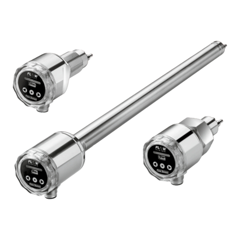
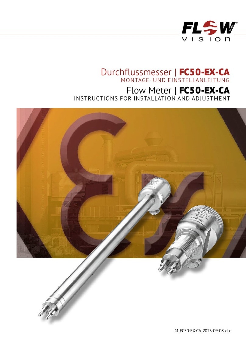
Flow vision FC50-EX-CA Guide

Durchflussmesser | FC50-EX-CA
MONTAGE- UND EINSTELLANLEITUNG
Flow Meter | FC50-EX-CA
INSTRUCTIONS FOR INSTALLATION AND ADJUSTMENT
M_FC50-EX-CA_1016_d_e

GMBH
Durchflussmesser | FC50-EX-CA
2
Bei der Montage der Messköpfe, dem
Anschließen und Einstellen des Gerätes
nur geschultes Fachpersonal einsetzen!
Eine Nichtbeachtung der Montage- und
Bedienungsanleitung kann zu erheblichen Schäden
am Gerät und an der Anlage führen. FlowVision
übernimmt gegenüber Kunden oder Dritten keine
Haftung, Gewährleistung oder Garantie für Mängel
oder Schäden, die durch fehlerhaften Einbau oder
unsachgemäße Handhabung unter Nichtbeachtung
der Montage- und Bedienungsanleitung verursacht
sind.
FlowVision behält sich das Recht vor, Spezifikationen
im Sinne des technischen Fortschritts jederzeit
zu ändern. Maßänderungen sind vorbehalten.
Änderungen sowie auch Irrtümer und Druckfehler
vorbehalten.
Equipment installation, connection and
adjustment by qualified personnel only!
Please follow these instructions carefully. Failure to
comply, or misuse of this equipment, could result
in serious damage both to the equipment itself and
to the installation. FlowVision is unable to accept
responsibility for customer or third party liability,
warranty claims or damage caused by incorrect
installation or improper handling resulting from
non-observance of these instructions.
All dimensions are for reference only. In the interest
of improved design, performance and cost-ef-
fectiveness the right to make changes in these
specifications without notice is reserved. Errors
and omissions excepted.

GMBH
Flow Meter | FC50-EX-CA
3
1 Ex-Umgebung
Angaben zum Explosionsschutz
Der Durchflussmesser FC50-EX-CA ist konstruiert
zur bestimmungsgemäßen Verwendung in explosi-
onsgefährdeten Bereichen nach Richtlinie 2014/34/
EU und kann in Bereichen der Gerätegruppe II,
Zone 2 (Gas) bzw. Zone 21 und 22 (Staub) ein-
gesetzt werden.
Er wurde nach den Bestimmungen der Normen
EN 60079-0:2012, EN 60079-15:2010 und EN
60079-31:2014 ausgelegt und trägt folgende
Kennzeichnung:
II 3G Ex nA IIC T4 Gc
II 2D Ex tb IIIC T120°C Db
Die zugehörige Baumusterprüfbescheinigungsnummer
ist EPS 11 ATEX 1 365 X.
Hinweise
• Die zulässige Umgebungstemperatur beträgt
-10 … +65 °C
• Das Gerät trägt folgende Warenkennzeichnung:
WARNUNG – Bei Einsatz in Zone 21 oder 22
(Staub) nach dem Abschalten 1 Minute warten
vor dem Öffnen.
1 Ex-atmosphere
Information on explosion protection
The flow meter FC50-EX-CA has been designed for
use in potentially explosive atmospheres to directive
2014/34/EU and is meant for use in applications
of equipment group II, zone 2 (gas), zone 21 and
zone 22 (dust).
It has been designed according to the European
standards EN 60079-0:2012, EN 60079-15:2010
and EN 60079-31:2014 and is marked as follows:
II 3G Ex nA IIC T4 Gc
II 2D Ex tb IIIC T120°C Db
It bears the EC-Type-Examination Certificate number
EPS 11 ATEX 1 365 X.
Remarks
• Permissible ambient temperature is -10 … +65 °C/
+14 … +149 °F
• The device is marked with the following warning
marking:
WARNING – If used in zone 21 or 22 (dust) wait
1 minute after swiching off before opening.
EX-UMGEBUNG | EX-ATMOSPHERE

GMBH
Durchflussmesser | FC50-EX-CA
4
2 Beschreibung
Der Durchflussmesser FC50-EX-CA dient zur Erfassung
des Durchflusses von Luft, Druckluft, Sauerstoff und
Stickstoff. Die folgenden Gerätemerkmale zeichnen
den FC50-EX-CA aus:
• Die Messung erfolgt - ohne mechanisch bewegte
Teile - nach dem kalorimetrischen Prinzip.
• Der gemessene Durchfluss wird dem Anwender als
4…20 mA Analogausgang zur Verfügung gestellt.
• FC50…MIN/MAX…: Ein MIN- oder MAX-Schaltpunkt
ist in 10 vordefinierten Stufen oder alternativ
stufenlos einstellbar und wird mittels LED-Balken
signalisiert.
• FC50…PUL…: Die Zuordnung Menge zu Puls (z.B.
1 Puls pro 10 Nm³) kann über die drei Tasten
eingestellt werden.
• Große Flexibilität durch verschiedene Prozess-
an schlüsse: Schraubvariante, Einsteckvariante
für Sensoradapter TP/Kugelhahn BV oder Ein-
schie bevariante für größere Nennweiten > DN 50
(siehe Fig. 1.)
• Der Sensoradapter TP-… ermöglicht den lage-
genauen Einbau und einfachen Austausch des
FC50-EX-CA in der Einsteckvariante. Der Kugelhahn
BV-… ermöglicht darüber hinaus jederzeit den
Einbau oder Austausch des FC50-EX-CA in der
Einsteckvariante durch Schließen der Zu- und
Ablaufleitung (siehe Fig. 2).
2 Description
Flow Meter FC50-EX-CA is designed to detect the
flow rate of air, compressed air, oxygen and nitrogen.
Important operational safety and reliability enhancing
features designed and built into these units include:
• Calorimetric flow measurement, which avoids the
need for moving parts in the flow.
• The measured flow rate is made available to the
user as a 4…20 mA analogue electrical signal.
• FC50…MIN/MAX…: The desired MIN or MAX
switch point can be adjusted steplessly or to 10
predefined values and is clearly indicated by a
LED-bar.
• FC50…PUL…: The quantity per pulse is adjustable
by the three keys (for example 1 pulse per 10
Nm³).
• Great flexibility by means of several types of
process connection: screw-in type, plug-in type
for sensor adapter TP/ball valve BV or push-in
type for larger pipe sizes > DN 50 (see fig. 1).
• The sensor adapter TP-… facilitates correct positio-
ning and replacement of the FC50-EX-CA plug-in
type. The ball valve BV-… enables installation or
removal of the FC50-EX-CA plug-in type by closing
the input and output pipe (see fig. 2).
BESCHREIBUNG | DESCRIPTION

GMBH
Flow Meter | FC50-EX-CA
5
BESCHREIBUNG | DESCRIPTION
Flow Direction
Strömungsrichtung
1.18
ø38
4036
14
SW2
DIN 3852
Form A
DIN 3852
form A
G1/2"A
90
3.54
1.571.42
.551
1.06
.709
1.50
ø18
ø38
58
14
ø18
18,2
90,2
Überwurfmutter G3/4"
cap nut G3/4"
O-Ring 15,3x2,2 (.602x.087) in Anlehnung an
DIN ISO 6149 Material: FKM
O-Ring 15,3x2,2 (.602x.087) following
DIN ISO 6149 material: FKM
locking slot
Arretierungsnut
3.55
2.28.717
.551
1.50
SW30
ø17,5
NPT1/2"-14
10
20
ø38
4036
14
SW27
90
3.54
1.571.42
.551 .394 .787
1.06
.689
1.50
Gewindeanschluss
Screw-in type process connection
Einschiebeanschluss
Push-in type process connection
Einsteckanschluss
Plug-in type process connection
14
ø18
SW15
53
ø38
ø1.49
2.09
ø.709
.590 in.
.552
Prozessanschluss 00: L = 300
Prozessanschluss 22: L = 200
Process connection 00: L = 300
Process connection 22: L = 200
Fig. 1
Alle Abmessungen in mm
All dimensions in mm

GMBH
Durchflussmesser | FC50-EX-CA
6
G
t
L
t
SW
ød
27
32
40
50
55
70
SW
50
64
78
94
110
138
11
12
14
15
15
19
tød
16
20
25
32
40
50
DN
Typ/Type
TP-01 …
TP-02 …
TP-03 …
TP-04 …
TP-05 …
TP-06 …
15
20
25
32
40
50
G
1/2"
3/4"
1"
11/4"
11/2"
2"
L
Arretierstift
retention pin
Sensoradapter TP-… / Sensor adapter TP-…:
Kugelhahn BV-… / Ball valve BV-…:
41
50
54
70
SW
88
100
110
131
21
24
24
28
tød
25
32
40
50
DN
Typ/Type
BV-03M3
BV-04M3
BV-05M3
BV-06M3
25
32
40
50
G
1"
11/4"
11/2"
2"
L
59
65
77
85
H
115
115
150
150
A
H
ød
G
t
SW
A
L
ø18
18.2
ø23.8
Anschweißset 05/
welding set 05 :
4
Anschweißstutzen / welded fitting
Edelstahl 1.4571 /stainless steel 1.4571/AISI 316 Ti
Arretierstift / retention pin
Überwurfmutter / cap nut
Edelstahl 1.4571/stainless steel 1.4571/AISI 316 Ti PN 315 bar/4569 psi
Messing/brass PN 25 bar / 363 psi
Rotguss (nur TP-03..) / red brass (only TP-03..) PN 16 bar / 232 psi
Messing vernickelt/nickel plated brass PN 25 bar / 363 psi
Typ/Type
ød
tt
L
SW
øD
DN
15
20
25
32
40
50
27
32
40
50
55
70
SW
50
70
80
100
110
140
15
15
15
15
15
15
tød
16
20
25
32
40
50
TP-01M1-SA
TP-02M1-SA
TP-03M1-SA
TP-04M1-SA
TP-05M1-SA
TP-06M1-SA
LøD
21.3
26.9
33.7
42.4
48.3
60.3
Edelstahl 1.4571/stainless steel 1.4571/AISI 316 Ti PN 315 bar/4569 psi
GMBH
GMBH
GMBH
BESCHREIBUNG | DESCRIPTION
Fig. 2
Alle Abmessungen in mm
All dimensions in mm

GMBH
Flow Meter | FC50-EX-CA
7
TECHNISCHE DATEN | TECHNICAL DATA
3 Technische Daten
Funktionsbereich:
Luft, Druckluft, Sauerstoff, Stickstoff
0 … 25/100 Nm/s (siehe Kapitel 9)
Zulässiger Temperaturbereich (Medium):
-10 … +90 °C
Zulässiger Temperaturbereich (Umgebung):
-10 … +65 °C
Druckfestigkeit Messkopf:
100 bar
Ansprechzeit: ca. 8 s *
Schutzart:
IP 65
Nennspannung:
DC 24 V (±20 %)
Analogausgang:
4…20 mA (12 bit)
Schaltausgang/Pulsausgang:
Power FET, max. 500 mA, kurzschlussfest
- Kennzeichnung gemäß den Bestimmungen
der EG-Richtlinie 2004/108/EG (EMV) und
EG-Richtlinie 2014/34/EU (ATEX)
Störfestigkeit:
EN 61000-6-2:2005
Störaussendung:
EN 61000-6-3:2007
* Verzögerungswerte gemessen bei Schalt punkt-
einstellung auf 25 Nm/s und einer Betriebs strömung
von 50 Nm/s nach plötzlichem Strömungsstillstand.
3 Technical Data
Operating range:
Air, compressed air, oxygen, nitrogen
0 … 25/100 Nm/s (see chapter 9)
Admissible temperature range (fluid):
-10 … +90 °C
Admissible temperature range (ambience):
-10 … +65 °C
Pressure resistance of the monitoring head:
100 bar/1450 psi
Response delay: approx. 8 s *
Degree of protection:
IP 65
Supply voltage:
DC 24 V (±20 %)
Analogue output:
4…20 mA (12 bit)
Switching output/pulse output:
Power FET, max. 500 mA, short circuit proof
- mark to demonstrate compliance with appli-
cable directives 2004/108/EC (EMC) and
2014/34/EU (ATEX)
Immunity to interference:
EN 61000-6-2:2005
Emitted interference:
EN 61000-6-3:2007
* Delay with the switch point set to 25 Nm/s and
the flow rate at 50 Nm/s, after a sudden complete
flow stoppage.

GMBH
Durchflussmesser | FC50-EX-CA
8
MECHANISCHER EINBAU | MECHANICAL INSTALLATION
4 Mechanischer Einbau
Achtung!
Beim Ein- und Ausbau des Durchflussmessers
überzeugen Sie sich, dass das Rohrsystem nicht
unter Druck steht.
1 Überprüfen, ob der einzubauende FC50-CA für
den Rohrinnendurchmesser an der Messstelle
ausgelegt ist:
2 Die Messfühler (S) müssen nebeneinander im
Rohr liegen (siehe Fig. 3):
4 Mechanical installation
Caution!
While installing or removing the flow meter please
make sure that the pipe system is unpressurized.
1 Check that the flow meter is suitable for the
inside pipe diameter at the measuring point:
2 The two sensors (S) must be side by side across
the direction of flow
(see fig. 3):
Fig. 3
F
S
F
S
F
S
F
Bei senkrechter Leitung: Bei waagerechter Leitung: Die Messfühler müssen neben-
Nur in Steigleitungen einbauen.* Nur von unten einbauen.* einander im Rohr liegen.
Vertical pipelines: Horizontal pipelines : The two sensors (S) must be
Fluid should be rising.* Flow meter should be side by side across the
mounted on the underside.* direction of flow .
* Bei Gasen ist die Einbaulage bei senkrechter und waagrechter Leitung beliebig.
* If the fluid to be measured is a gas, the mounting attitude of the flow meter is unimportant in either vertical or horizontal pipelines.
F
S
F
S
F
S
F
Bei senkrechter Leitung: Bei waagerechter Leitung: Die Messfühler müssen neben-
Nur in Steigleitungen einbauen.* Nur von unten einbauen.* einander im Rohr liegen.
Vertical pipelines: Horizontal pipelines : The two sensors (S) must be
Fluid should be rising.* Flow meter should be side by side across the
mounted on the underside.* direction of flow .
* Bei Gasen ist die Einbaulage bei senkrechter und waagrechter Leitung beliebig.
* If the fluid to be measured is a gas, the mounting attitude of the flow meter is unimportant in either vertical or horizontal pipelines.
FC50…PC1 Einsatz mit Sensoradapter TP01
FC50…PC2 Einsatz mit Sensoradapter TP02
FC50…PC3 Einsatz mit Sensoradapter TP03/BV03
FC50…PC4 Einsatz mit Sensoradapter TP04/BV04
FC50…PC5 Einsatz mit Sensoradapter TP05/BV05
FC50…PC6 Einsatz mit Sensoradapter TP06/BV06
FC50…TC1 Einsatz in Rohren mit
Innendurchmesser < 26,0 mm
FC50…TC2 Einsatz in Rohren mit
Innendurchmesser 26,0…32,8 mm
FC50…TC3 Einsatz in Rohren mit
Innendurchmesser > 32,8…40,3 mm
FC50…TC4 Einsatz in Rohren mit
Innendurchmesser > 40,3…53,0 mm
FC50…TC5 Einsatz in Rohren mit
Innendurchmesser > 53,0 mm
FC50…FC1 Einsatz in Rohren mit
Innendurchmesser > 50,0…67,0 mm
FC50…FC2 Einsatz in Rohren mit
Innendurchmesser > 67,0 mm
FC50…PC1 For use in sensor adapter TP01
FC50…PC2 For use in sensor adapter TP02
FC50…PC3 For use in sensor adapter TP03/BV03
FC50…PC4 For use in sensor adapter TP04/BV04
FC50…PC5 For use in sensor adapter TP05/BV05
FC50…PC6 For use in sensor adapter TP06/BV06
FC50…TC1 For pipes with inside diameter
< 26,0 mm
FC50…TC2 For pipes with inside diameter
26,0…32,8 mm
FC50…TC3 For pipes with inside diameter
> 32,8…40,3 mm
FC50…TC4 For pipes with inside diameter
> 40,3…53,0 mm
FC50…TC5 For pipes with inside diameter
> 53,0 mm
FC50…FC1 For pipes with inside diameter
> 50,0…67,0 mm
FC50…FC2 For pipes with inside diameter
> 67,0 mm

GMBH
Flow Meter | FC50-EX-CA
9
MECHANISCHER EINBAU | MECHANICAL INSTALLATION
D
20 x D
D
20 x D
• Um Strömungsturbulenzen an den Messfühlern
zu vermeiden, den Durchflussmesser nur in
gerade Rohrleitungen einbauen. Auf ausrei-
chenden Abstand zu Querschnittsänderungen,
Rohrkrümmungen und Ventilen/Schiebern achten
(siehe Fig. 4).
• Um evtl. Funktionsstörungen auszuschließen sind
energiereiche induktive, kapazitive und hochfre-
quente Einstreuungen zu vermeiden.
• The flow meter should be installed only in a
straight section of piping. To avoid any effects of
turbulence there should be a specific distance
before and a specific distance after the flow meter
before or after any bends, valves and changes in
pipe diameter (see fig. 4).
• Avoid installing the flow meter in known areas of
high electrical inductance, capacitance, or high-
frequency electromagnetic fields.
MECHANISCHER EINBAU | MECHANICAL INSTALLATION
Fig. 4

GMBH
Durchflussmesser | FC50-EX-CA
10
3
• Einschraubvariante:
Den Durchflussmesser mit entsprechendem
Dichtungsmaterial in das vorgesehene Rohrfitting
einschrauben und mit einem Gabelschlüssel (SW
27) an den Schlüsselansatzflächen festziehen.
Beim Anziehen des Durchflussmessers die VDI
Richtlinien 2230 für das Anzugsmoment unbedingt
beachten.
Die beiden Messfühler (S) müssen im einge bauten
Zustand nebeneinander im Strö mungs medium liegen.
Dies ist der Fall, wenn die Schlüsselansatzflächen
(F) parallel zur Rohrleitung stehen (siehe Fig. 3).
Bis 56 mm Rohr innendurchmesser muss der
Einschraubstutzen bündig mit der Rohrinnenwand
sein. Größer 56 mm Rohrinnendurchmesser muss
die Fühlermitte (schräger Absatz) auf 1/8 des
Rohrinnendurchmessers eingeschraubt werden.
Der Pfeil (Laserbeschriftung) an der Seite des
Gehäuses muss in Strömungsrichtung zeigen
(siehe Fig. 5).
3
• screw-in type:
When tightening the flow meter please use the flats
provided (SW 27) and do not turn or apply torque
to the housing. Do not overtighten. It is important
that thread sealing compound or material of the
correct type for the fluid is used when fitting the
monitoring head.
The two sensors (S) of the flow meter must be
aligned side by side directly across the direction
of flow. The sensors are correctly positioned when
the wrench flats (F) are aligned parallel with the
pipe (see fig. 3). For inside pipe diameters up to
56 mm (2.2 in) the shaft end must be in line with
the inner pipe wall. For inside pipe diameters above
56 mm (2.2 in) the shoulder of the two sensors
(7 mm (0.28 in) from the tip) must be positioned
at 1/8 of inside pipe diameter Ø i. The arrow (laser
marking) at the side of the housing must show in
direction of flow (see fig. 5).
12,5 mm
øi = 100 mm
1/8 øi
Fig. 5
MECHANISCHER EINBAU | MECHANICAL INSTALLATION

GMBH
Flow Meter | FC50-EX-CA
11
• Einsteckvariante:
Den Sensoradapter TP-… oder den Kugelhahn
BV-… in die Rohrleitung einbauen. Dabei die
Strömungsrichtung beachten (siehe Fig. 6).
Durchflussmesser mit O-Ring in den Sensoradapter
TP-... oder Kugelhahn BV-... einstecken (siehe
Fig. 6) und die Überwurfmutter festschrauben.
Die Ausrichtung der Sensoren ist nach der
Verschraubung der Überwurfmutter durch den
Arretierstift garantiert.
• plug-in type:
Install the sensor adapter TP-… or the ball valve
BV-… in the pipe. Observe the flow direction (see
fig. 6).
Insert the flow meter with O-ring into the sensor
adapter TP-... or the ball valve BV-... (see fig. 6) and
tighten the union nut. The retention pin ensures
correct alignment of the sensors after the union
nut has been tightened.
MECHANISCHER EINBAU | MECHANICAL INSTALLATION
MECHANISCHER EINBAU | MECHANICAL INSTALLATION
Bohrung
ø24 mm
bore
ø.945 in.
cap nut G3/4"
Überwurfmutter G3/4"
Sensoradapter TP-… / Sensor adapter TP-…:
Kugelhahn BV-… / Ball valve BV-…:
G
Stecker M12 x 1
plug-in connector M12 x 1
ød
Exakte Positionierung des Sensors ist sichergestellt (Arretierungsstift/-Nut)
Correct position of the sensor is ensured (retention pin/locking slot)
Exakte Positionierung des Sensors ist sichergestellt (Arretierungsstift/-Nut)
Correct position of the sensor is ensured (retention pin/locking slot)
Exakte Positionierung des Sensors ist sichergestellt
(Arretierungsstift/-Nut)
Correct position of the sensor is ensured
(retention pin/locking slot)
cap nut G3/4"
Überwurfmutter G3/4"
Dichtung: O-Ring 15,3 x 2,2 mm in Anlehnung an DIN ISO 6149
sealing: O-ring 15.3 x 2.2 mm/.602 x .0866 in. following DIN ISO 6149
Dichtung: O-Ring 15,3 x 2,2 mm in Anlehnung an DIN ISO 6149
sealing: O-ring 15.3 x 2.2 mm/.602 x .0866 in. following DIN ISO 6149
Dichtung: O-Ring 15,3 x 2,2 mm in Anlehnung an DIN ISO 6149
sealing: O-ring 15.3 x 2.2 mm/.602 x .0866 in. following DIN ISO 6149
Anschweißset 05
Anschluss nach DIN ISO 6149
Welding set 05
to DIN ISO 6149
Stecker M12 x 1
plug-in connector M12 x 1
cap nut G3/4"
Überwurfmutter G3/4"
Strömungsrichtung
flow direction
GMBH
GMBH
Strömungsrichtung
flow direction
Strömungsrichtung
flow direction
Fig. 6

GMBH
Durchflussmesser | FC50-EX-CA
12
• Einschiebevariante:
Die beiden Messfühler (S) müssen im eingebauten
Zustand nebeneinander im Strömungsmedium liegen.
Dies ist der Fall, wenn die Schlüsselansatzflächen
(F) parallel zur Rohrleitung stehen (siehe Fig. 3).
Die Fühlermitte (schräger Absatz) muss bei 1/8
des Rohrinnendurchmessers positioniert werden.
Der Pfeil (Laserbeschriftung) an der Seite des
Gehäuses muss in Strömungsrichtung zeigen
(siehe Fig. 7).
• push-in type:
The two sensors (S) on the flow meter must be
aligned side by side directly across the direction
of flow. The sensors are correctly positioned when
the wrench flats (F) are aligned parallel with the
pipe (see fig. 3). The shoulder of the two sensors
(7 mm (0.28 in) from the tip) must be positioned
at 1/8 of inside pipe diameter Ø i. The arrow (laser
marking) at the side of the housing must show in
direction of flow (see fig. 7).
Fig. 7
MECHANISCHER EINBAU | MECHANICAL INSTALLATION
Durchflussmesser mit Sicherungsset wie folgt
befestigen (siehe Fig. 9):
– Erstes Glied der Kette (1) zwischen die Schelle
(3) spannen (Anzugsdrehmoment 10 Nm).
– Schraubglied (2) in das Kettenglied einhängen
und mit der straffen Kette verschließen.
Achtung!
Sicherungsset auf Festigkeit überprüfen!
Die Sicherungskette muss straff montiert werden.
Achtung!
Vor Inbetriebnahme das Rohrsystem unter Druck
setzen und es auf Festigkeit und Leckagen über-
prüfen.
Fix flow meter with locking set (see fig. 9):
- Fix first link of chain (1) into the clip (3) (tigh-
tening torque 10 Nm)
- Put chain catch (2) into link and fasten with the
tight chain.
Caution!
Check locking set with regard to strength!
The locking chain must be mounted as tightly
as possible.
Caution!
Before start-up please pressurize the pipe system
and check with regard to leakages and strength.
1/8 vom øi
1/8 of øi
øi (Rohrinnendurchmesser)
øi (inside pipe diameter)
Strömungsrichtung
flow direction
Verschraubung
(Edelstahl-Schneidring)
threaded installation bush
(stainless steel ring)
F

GMBH
Flow Meter | FC50-EX-CA
13
Sicherungsset 01 – Best. Nr. 0Z122Z000204
Locking set 01 – 0Z122Z000204
1 Kette 4 x 32 DIN 5685 (ca. 1 m)
2 Schraubglied NG 5
3 Schelle DN15 nach DIN 11850
1 chain 4 x 32 DIN 5685 (approx. 1 m)
2 catch for chain NG 5
3 clip with screw and nuts DN15 to DIN 11850
321
MECHANISCHER EINBAU | MECHANICAL INSTALLATION
Fig. 9
MECHANISCHER EINBAU | MECHANICAL INSTALLATION

GMBH
Durchflussmesser | FC50-EX-CA
14
5 Anschließen
Achtung!
Überprüfen, ob die Versorgungsspannung mit der
Nennspannung des Durchflussmessers überein-
stimmt.
1 Verbindung mit dem zugehörigen Kabel entspre-
chend dem Anschlussbild (siehe Fig. 10) herstellen.
2 Versorgungsspannung anschließen. Der
Durchflussmesser geht in die Heizphase. Zu
Beginn der Heizphase leuchtet nur die erste
LED ganz links grün. Alle fünf Sekunden beginnt
eine weitere LED grün zu leuchten bis am Ende
der Heizphase alle zehn LEDs grün leuchten.
Anschließend geht der Durchflussmesser in den
normalen Betrieb über.
5 Electrical connection
Caution!
Check that the supply voltage corresponds with the
voltage rating shown on the system.
1 Connect the supply by means of the appropriate
cable (see fig. 10).
2 Connect the power supply. The flow meter starts
to heat up. At the beginning of the heating process
only the first LED (left side) lights green. Every five
seconds an additional LED starts to light green.
When the heating process is finished all ten LEDs
light green. After that the flow meter starts the
usual measuring operation.
ANSCHLIESSEN | ELECTRICAL CONNECTION
Fig. 10
braun/brown
rot/red
schwarz/black
FC50-EX-CA
+ DC 24 V
Last/load
max. 500 mA
Last/load
max. 500 Ω
(inkl. Kabelwiderstand/
incl. cable resistance)
– Minus
minus
Schaltausgang/
Pulsausgang
switching output/
pulse output
Analogausgang
analogue output
+UB
-UB
orange/orange

GMBH
Flow Meter | FC50-EX-CA
15
6 Anzeige und Bedienung
Damit der FC50-EX-CA bedient werden kann muss
zunächst der Frontdeckel abgeschraubt werden.
Anschließend erfolgt die Bedienung des FC50-EX-CA
über die drei Tasten ,
▲
und
▲
.
Achtung !
WARNUNG – Bei Einsatz in Zone 21 oder 22
(Staub) nach dem Abschalten 1 Minute warten vor
dem Öffnen.
Nach Beenden des Bedienvorgangs muss der
Frontdeckel wieder aufgeschraubt werden. Geschieht
dies nicht ist die Schutzart IP 65 nicht gewährleistet.
Als Anzeige besitzt der FC50-EX-CA einen 10-fach
LED-Balken, über den der aktuelle Durchfluss
dargestellt wird. Dabei wird der Funktionsbereich
in 10 gleich große Teile unterteilt. Jedes 10tel des
Funktionsbereichs wird durch eine LED dargestellt.
FC50…MIN/MAX…:
Befindet sich der Durchfluss im er laubten Bereich
(MIN-Version: größer als der einge stellte Schaltpunkt,
MAX-Version: kleiner als der eingestellte Schaltpunkt)
wird der gemessene Durchfluss mit einem grünen Balken
dargestellt. Der Schaltpunkt ist in diesem Fall orange.
Befindet sich der Durchluss außerhalb des erlaubten
Bereichs (MIN-Version: kleiner als der eingestellte
Schaltpunkt, MAX-Version: größer als der eingestellte
Schaltpunkt) wird der gemessene Durchfluss mit
einem roten Balken dargestellt. Der Schaltpunkt
blinkt in diesem Fall rot (siehe Fig. 11).
FC50…PUL…:
Bei Geräten mit Pulsausgang wird im normalen
Betriebsmodus der gemessene Durchfluss als grüner
Balken dargestellt.
6 Display and operation
To operate the FC50-EX-CA the front cover must be
screwed off first. After that the FC50-EX-CA can be
operated by three keys: :
▲
, and
▲
.
Caution!
WARNING – If used in zone 21 or 22 (dust) wait 1
minute after swiching off before opening.
After the operation is finished the front cover must be
screwed on again. This guarantees the IP 65 rating.
The FC50-EX-CA has an LED bar with 10 LEDs which
shows the actual flow rate. The operating range is
split into 10 equal parts. Every part of the operating
range is represented by one LED.
FC50…MIN/MAX…:
When the flow rate is inside the admissible range
(MIN-version: higher than the set switching point,
MAX-version: lower than the set switching point) the
measured flow rate is shown as a green bar. In this
case the switching point is orange.
When the flow rate is outside the admissible range
(MIN-version: lower than the set switching point,
MAX-version: higher than the set switching point)
the measured flow rate is shown as a red bar. In
this case the switching point blinks red (see fig. 11).
FC50…PUL…:
Devices with pulse output show the measured flow
rate as a green bar in usual operating mode.
ANZEIGE UND BEDIENUNG | DISPLAY AND OPERATION

GMBH
Durchflussmesser | FC50-EX-CA
16
ANZEIGE UND BEDIENUNG | DISPLAY AND OPERATION
Fig. 11
MIN-Version: Strömung im erlaubten Bereich
MIN-version: Flow inside the admissible range
MAX-Version: Strömung im erlaubten Bereich
MAX-version: Flow inside the admissible range
MIN-Version: Strömung außerhalb des erlaubten Bereichs
MIN-version: Flow outside the admissible range
MAX-Version: Strömung außerhalb des erlaubten Bereichs
MAX-version: Flow outside the admissible range
= grün/green
= grün/green
= rot/red
= rot/red
= orange/orange
= orange/orange
= rot blinkend/red blinking
= rot blinkend/red blinking

GMBH
Flow Meter | FC50-EX-CA
17
7 Schaltpunkteinstellung
(nur mit FC50…MIN/MAX… möglich)
Der Schaltpunkt kann mittels der Tasten
▲
u n d
▲
in Schritten von 10 % des Funktionsbereichs verstellt
werden. Dadurch ist es möglich den Schaltpunkt
unabhängig vom aktuell vorliegenden Durchfluss auf
5 %, 15 %, 25 %,…, 85 % und 95 % des
Funktionsbereichs einzustellen.
Soll der Schaltpunkt auf einen bestimmten anderen
Wert eingestellt werden muss folgendermaßen vor-
gegangen werden:
1 In der zu überwachenden Rohrleitung ist der
kritische Durchfluss mit zugehöriger Temperatur
herzustellen, bei welcher der Schaltausgang
des Durchflussmessers ansprechen soll. Der
kritische Durchfluss kann z.B. durch Reduzierung
der Pumpenleistung oder mittels Absperrventil
in der Leitung erreicht werden. Die Aufheizzeit
des Messkopfes sollte abgewartet werden, diese
beträgt ca. 15 Minuten.
Achtung!
Auf gleichbleibende Strömungsbedingungen achten.
2 Durch drücken der Taste kann nun der aktuell
gemessene Durchfluss als Schaltpunkt gesetzt werden.
8 Konfiguration des Pulsausgangs
(nur mit FC50…PUL… möglich)
Zur Konfiguration des Pulsausgangs muss folgen-
dermaßen vorgegangen werden:
1 Durch drück der Taste wird der Konfigura tions-
modus aufgerufen.
2 Im Konfigurationsmodus werden eine bis fünf
rote LEDs angezeigt. Die Anzahl der angezeigten
LEDs steht für die Zuordnung einer bestimmten
Menge pro Puls:
1 rote LED => 1 Puls pro 0,01 Nm³
2 rote LEDs => 1 Puls pro 0,1 Nm³
3 rote LEDs => 1 Puls pro 1 Nm³
4 rote LEDs => 1 Puls pro 10 Nm³
5 rote LEDs => 1 Puls pro 100 Nm³
Die Menge pro Puls kann mittels der Tasten
▲
und
▲
verstellt werden.
3 Der Konfigurationsmodus wird durch erneutes
drücken der Taste wieder beendet.
7 Setting of the switching point
(only possible with FC50…MIN/MAX…)
The switching point can be set by the
▲
and
▲
keys in steps of 10 % of the operating range. This
allows the operator to set the switching point to 5
%, 15 %, 25 %,…, 85 % and 95 % of the operating
range regardless of the actual flow rate.
If the switching point is to be set to another value
the following steps must be done:
1 Start by bringing the system to the critical flow rate
at which the switching output of the flow meter
should respond and to its normal operating tem-
perature and allow it to reach thermal stabilization.
This takes at least 15 minutes. The critical flow rate
can be simulated by reducing the pump power
or by means of stop valve installed in the pipe.
Caution!
Care should be taken to ensure that the flow is
continuous.
2 Now the actual measured flow speed can be set
as switching point value by pressing .
8 Configuration of the pulse output
(only possible with FC50…PUL…)
The pulse output can be configured by the follow-
ing steps:
1 Press to enter the configuration mode.
2
In the configuration mode one, two, three, four
or five LEDs light red. The number of red LEDs
shows the assignment of a certain quantity
per pulse:
1 red LED => 1 pulse per 0,01 Nm³
2 red LEDs => 1 pulse per 0,1 Nm³
3 red LEDs => 1 pulse per 1 Nm³
4 red LEDs => 1 pulse per 10 Nm³
5 red LEDs => 1 pulse per 100 Nm³
The quantity per puls can be adjusted by the
▲
and
▲
keys.
3 Press again to exit the configuration mode.
EINSTELLUNG | SETTING

GMBH
Durchflussmesser | FC50-EX-CA
18
Achtung!
Der FC50-EX-CA gibt maximal 10 Pulse pro Sekunde
aus (Pulsweite 50 ms). Müsste der FC50-EX-CA
aufgrund eines hohen Durchflusses mehr als 10
Pulse ausgeben, bleibt der Pulsausgang dauerhaft
high. Die in diesem Fall nicht ausgegebenen Pulse
werden nach Ende/Beheben des Fehlers nicht
nachträglich ausgegeben.
9 Analogausgang
Der lineare Analogausgang ist fest auf einen durch
den Bestellschlüssel definierten Bereich eingestellt.
FC50…00/01/02…:
4 mA entsprechen immer 0 Nm/s, 20 mA entspre-
chen dem Funktionsbereichsendwert des Gerätes:
FC50-CA...FB2...: 100 Nm/s
FC50-CA...FB1...: 25 Nm/s
Der Normvolumenstrom ist vom Rohrinnendurchmesser
an der Messstelle abhängig und kann mit folgender
Gleichung berechnet werden:
Q = v · A
Q [Nm³/h] – Normvolumenstrom
v [Nm/h] – mittlere Normgeschwindigkeit
A [m²] – Rohrinnenquerschnitt
FC50…11…:
4 mA entsprechen immer 0 Nm
3
/h, 20 mA entspre-
chen dem Funktionsbereichsendwert des Gerätes:
Diesen können Sie der folgenden Tabelle entnehmen:
10 Tastensperre
Durch Drücken der Taste für mindestens fünf
Sekunden kann die Tastatur gesperrt warden. Durch
erneutes Drücken der Taste für mindestens fünf
Sekunden kann die Tastensperre wieder aufgeho-
ben werden.
WARTUNG | MAINTENANCE
Caution!
The FC50-EX-CA emits not more than 10 pulses per
second (puls with 50 ms). If the FC50-EX-CA has
to emit more than 10 pulses because of a high flow
rate, the pulse output stays permanently high. The
pulses which are not emitted in this case also are
not emitted subsequently after the end of the error.
9 Analogue output
The linear analogue output is factory preset depen-
ding on the order code.
FC50…00/01/02…:
4 mA always corresponds to 0 Nm/s, 20 mA corre-
sponds to the operating range final value of the device:
FC50-CA...FB2...: 100 Nm/s
FC50-CA...FB1...: 25 Nm/s
The standard volume flow is determined by the
inner pipe diameter. It can be calculated with the
following equation:
Q = v · A
Q [Nm³/h] – standard volume flow
v [Nm/h] – average standard velocity
A [m²] – inner pipe cross section
FC50…11…:
4 mA always corresponds to 0 Nm
3
/h, 20 mA corre-
sponds to the operating range final value of the device:
You find the operating range final value in the fol-
lowing table:
10 Keylock
The keyboard can be locked by pressing for at
least five seconds. If the key is pressed again for
at least five seconds the keyboard can be released.
Sensoradapter/sensor adapter Funktionsbereich 1/operating range 1
(FC50-CA…FB1…)
Funktionsbereich 2/operating range 2
(FC50-CA…FB2…)
TP-01(FC50-CA…PC1…) 18,10 Nm³/h 72,38 Nm³/h
TP-02 (FC50-CA…PC2…) 28,27 Nm³/h 113,1 Nm³/h
TP-03/BV-03 (FC50-CA…PC3…) 44,18 Nm³/h 176,7 Nm³/h
TP-04/BV-04 (FC50-CA…PC4…) 72,38 Nm³/h 289,5 Nm³/h
TP-05/BV-06 (FC50-CA…PC5…) 113,1 Nm³/h 452,4 Nm³/h
TP-06/BV-06 (FC50-CA…PC6…) 176,7 Nm³/h 706,9 Nm³/h

GMBH
Flow Meter | FC50-EX-CA
19
STÖRUNGEN | DIFFICULTIES
The actual state of the keyboard lock is stored
power fail-safe.
11 Maintenance and recalibration
For calorimetric flow meters, the interval between
calibrations is dependent on the application since
calibration drift is predominantly caused by conta-
mination of the sensor surfaces. If the fluid is not
clean (i.e. contains particulates), then gentle cleaning
of the sensor elements can be effective at regular
intervals. The cleaning interval will depend upon
the nature and extent of the contamination. Avoid
damaging the sensor during cleaning.
Determination of recalibration intervals:
• If the measurement is critical, then a calibration
audit should be undertaken by performing reca-
libration checks once a year for a period of 2
years. Increase that period to twice a year if the
application fluid is not clean. Depending on the
results of the audit, the next recalibration check
interval can be increased or decreased accordingly.
• For non-critical applications and or where the fluid
is clean, a recalibration interval of every 2 to 3
years is recommended.
12 Operating difficulties
Problem:
Unsteady measuring value.
Solution:
• Ensure flow meter has been correctly installed in
accordance with chapter 3.
• Remove the flow meter and clean the sensors.
Problem:
Measured flow rate is outside the operating range.
Solution:
• Check the sensor for mechanical damages.
Der aktuelle Status der Tastensperre wird span-
nungsausfallsicher gespeichert.
11 Wartung und Nachkalibrierung
Für kalorimetrische Messgeräte ist die Zeitspanne
von der Kalibrierung bis zu dem Zeitpunkt an
dem Abweichungen auftreten, abhängig von den
Verunreinigungen, denen die Messfühler ausgesetzt
sind. Falls das Medium verunreinigt ist (z.B. durch
Partikel) sind regelmäßige Reinigungsintervalle der
Messfühler empfehlenswert. Die Intervalle sind
abhängig von der Art und Beschaffenheit wie auch
vom Umfang der Verunreinigung. Beim Reinigen
sind mechanische Verletzungen der Messfühler zu
vermeiden.
Bestimmung der Nachkalibrierungsintervalle:
• Bei kritischen Messungen und um die Nach-
kalibrierungsintervalle zu ermitteln, sollte eine
Kalibrierprüfung, auf die Dauer von zwei Jahren,
einmal jährlich stattfinden. Bei Einsatz in verunrei-
nigten Medien zweimal im Jahr. Abhängig von den
Ergebnissen dieser Prüfungen kann die nächste
Nachkalibrierung dann früher oder später gesetzt
werden.
• Für nichtkritische Anwendungen oder bei Einsatz
in Medien, die sich nicht an den Messfühlern
festsetzen, wird eine Nachkalibrierung alle zwei
bis drei Jahre empfohlen.
12 Störungen beseitigen
Störung:
Schwankender Messwert.
Beseitigung:
• Überprüfen, ob der Durchflussmesser entsprechend
den Angaben in Kapitel 3 „Mechanischer Einbau“
eingebaut ist.
• Durchflussmesser ausbauen und Messfühler
reinigen.
Störung:
Gemessener Durchfluss außerhalb des Funktions-
bereichs.
Beseitigung:
• Messfühler auf mechanische Beschädigungen
prüfen

FlowVision GmbH
Im Erlet 6
90518 Altdorf
Telefon 0049 (9187) 9 22 93 - 0
Telefax 0049 (9187) 9 22 93 - 29
www.flowvision-gmbh.de
Other manuals for FC50-EX-CA
1
Table of contents
Other Flow vision Measuring Instrument manuals
Flow vision
Flow vision FC50-dbEX-CA User manual
Flow vision
Flow vision FC50-EX-CA User manual
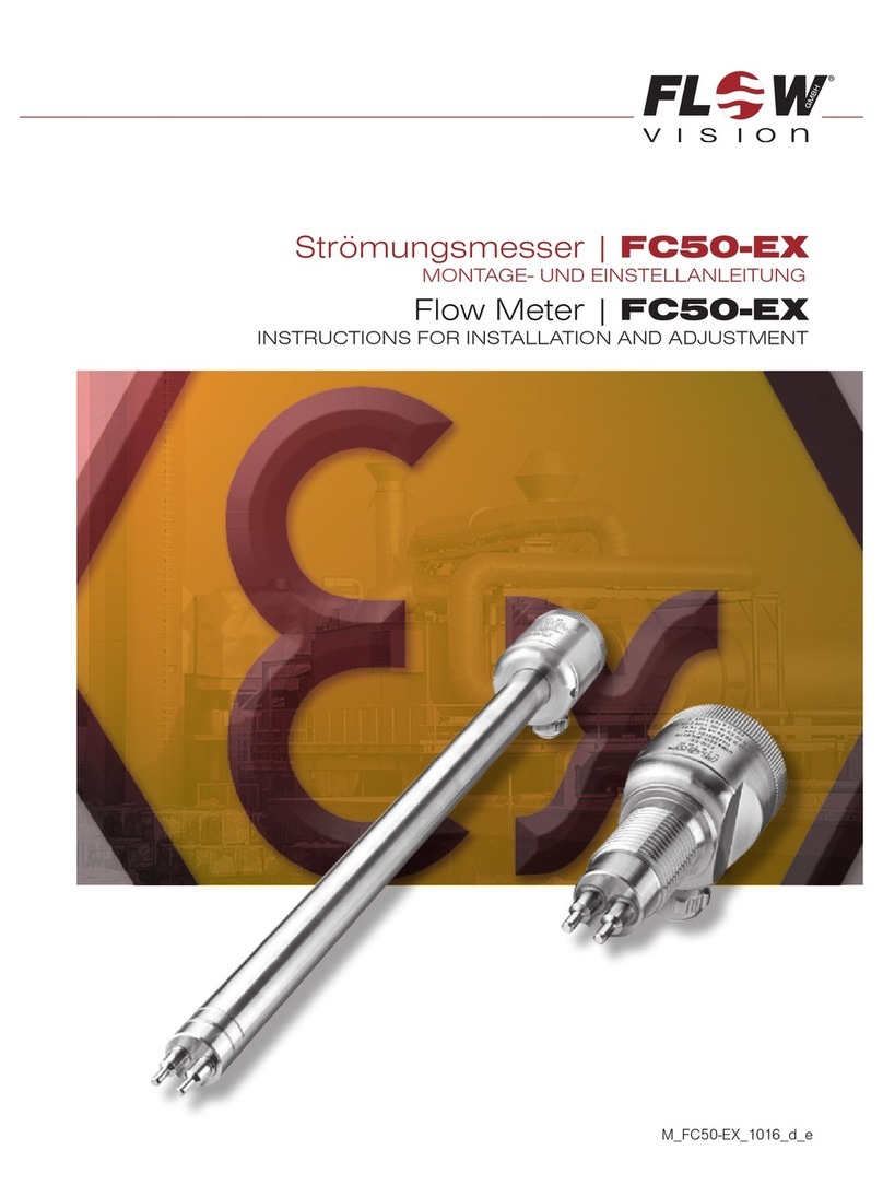
Flow vision
Flow vision FC50-EX Guide

Flow vision
Flow vision FC50 User manual

Flow vision
Flow vision FC50-EX User manual
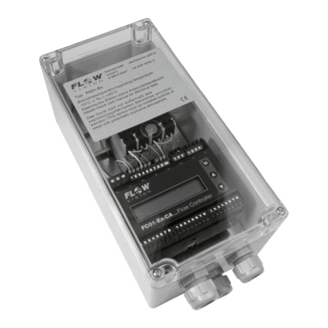
Flow vision
Flow vision FC01-Ex Instruction Manual

Flow vision
Flow vision FC50-dbEX-CA Guide
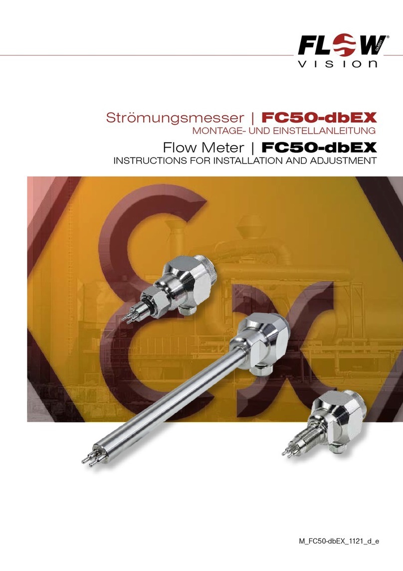
Flow vision
Flow vision FC50-dbEX Guide
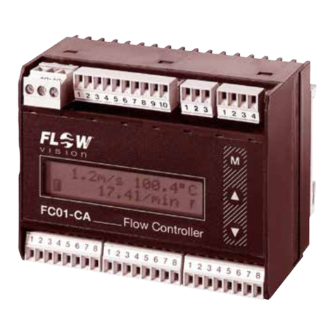
Flow vision
Flow vision FC 01- CA User manual
Flow vision
Flow vision FS20-dbEX Guide
