INS_CNFE3TX2CXMS(U,E)_REV– Rev. 7.11.18 PAGE 5
QUICK START GUIDE CNFE3TX2CXMS(U,E)
TECH SUPPORT: 1.888.678.9427
Getting Started
1.1 About the CNFE3TX2CXMS(U,E)
The CNFE3TX2CXMS(U,E) is a reliable 4G LTE Cellular Router with two 10/100Base-T(X)
ports where one is for LAN and the other one for WAN. It supports 802.1X and MAC filter for
security control and can be operate in three routing modes: Dynamic/Static IP Route, PPPoE
Authentication, and Modem Dial-up. In the mode of Modem Dial-up, it supports GPRS/3G/3.5G/
LTE modem via the internal 4G module. You can set up a WLAN environment that fulfills
demands of various applications by dialing up cellular modems. In addition, the LAN port of
CNFE3TX2CXMS(U,E) is P.D.-enabled which is fully compliant with IEEE802.3af PoE specification.
This feature extends the layout up to 100 meters.
1.2 Software Features
»Secure management by HTTPS
»Multiple WAN connection types supported: Dynamic/Static IP, PPPoE, Modem/Dial-up
»IP table to prevent access from unauthorized IP address
»Supports NAT setting (virtual server, port trigger, DMZ, and UPnP)
»Versatile modes & event alarm by e-mail
»Event warning by Syslog, e-mail, SNMP trap, relay output, and beeper
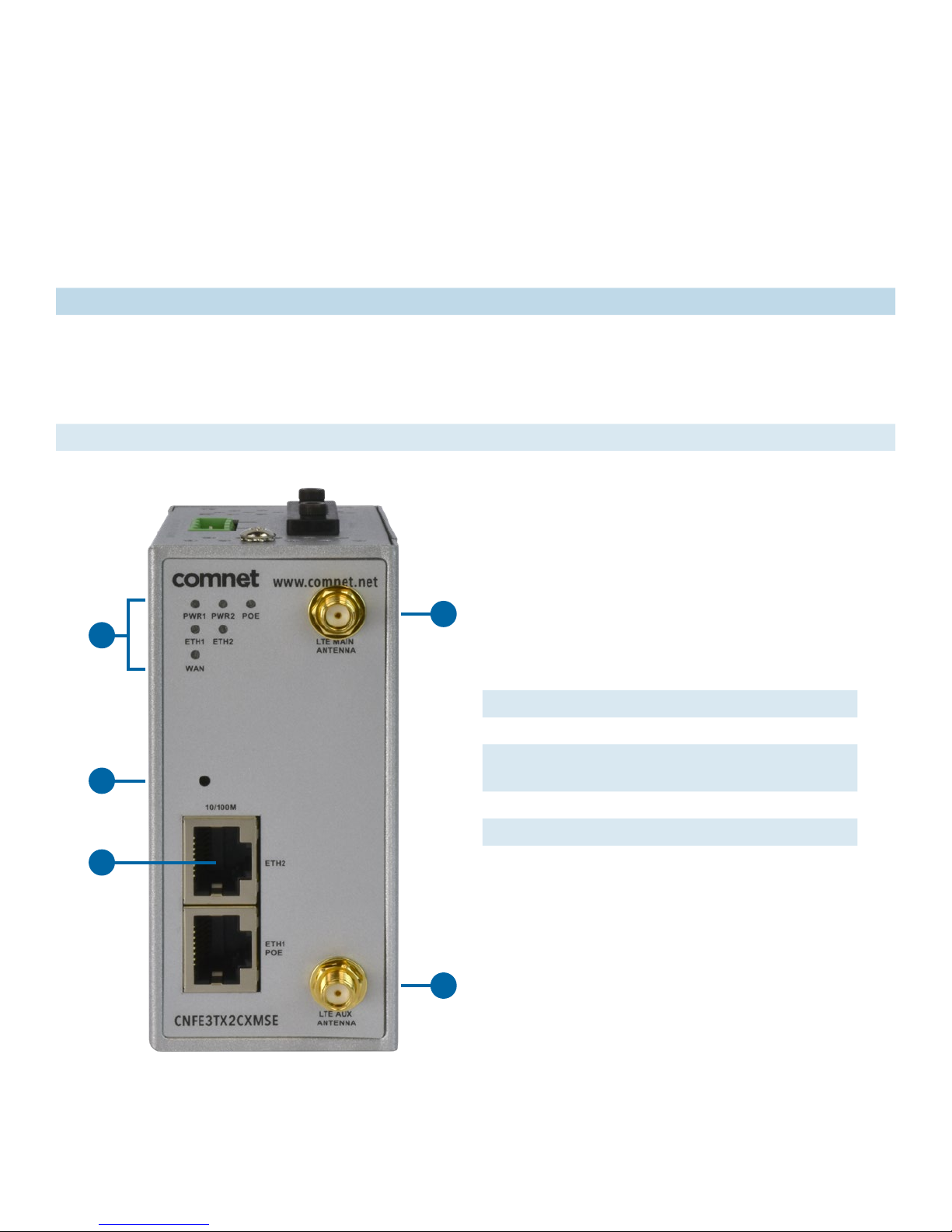
1.3 Hardware Features
»2 × 10/100Base-T(X) Ethernet ports for WAN / LAN connection individually.
»1 × SIM card slot
»4G LTE dial-up modem included
»1KV isolation for PoE P.D. port
»Dual DC inputs
»Operating temperature: -40 to 60 °C
»Storage temperature: -40 to 85 °C
»Operating humidity: 5% to 95%, non-condensing
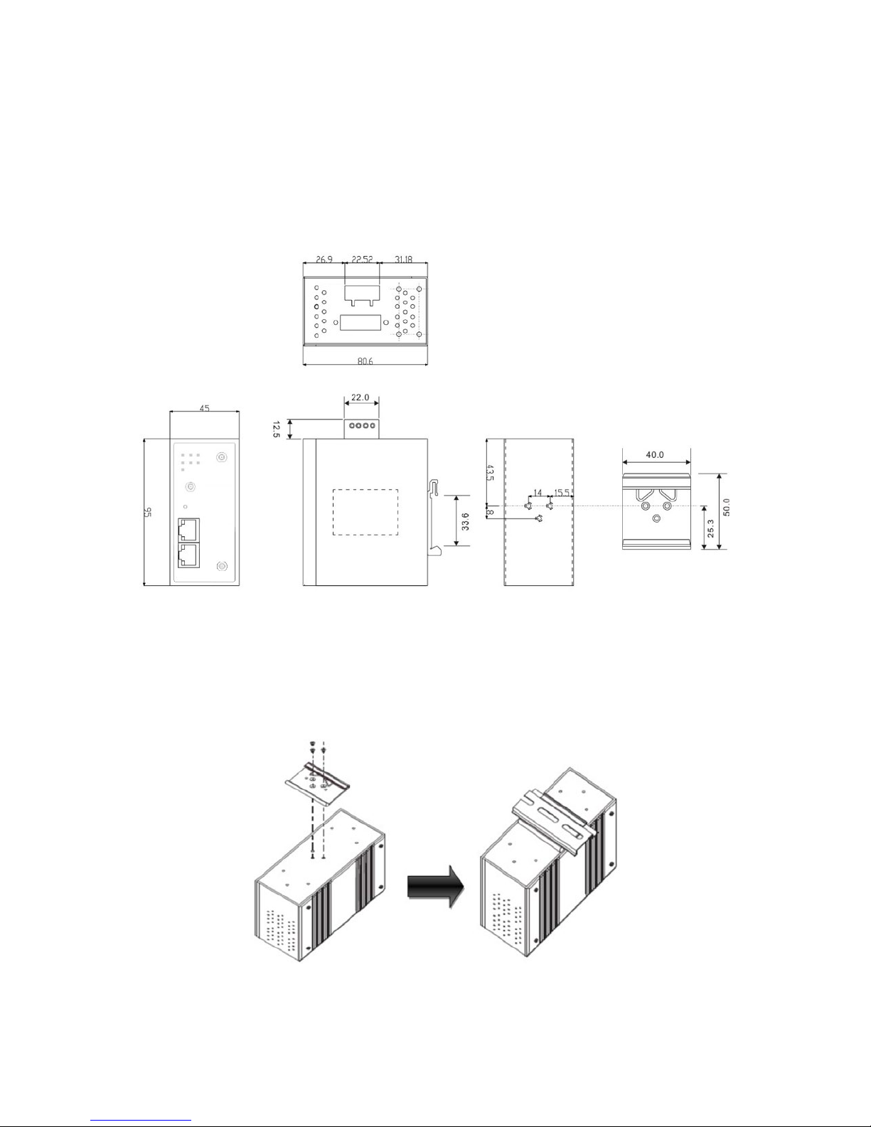
»DIN-Rail and Wall-mount enabled
»Casing: IP-30
»Dimensions: 45(W) × 80.6(D) × 95(H) mm