Compac WD 1600 User manual

Operating Manual for Compac Wheel dolly
Model WD 1600
This operating manual is also
available on request in other
languages at no charge.
Before using the product:
Read and understand this manual.

Contents
To the owner / user ........................................................................................................................................................3
Warranty ......................................................................................................................................................................3
Safety ..............................................................................................................................................................................3
Safety symbols ...........................................................................................................................................................4
Safety and information labels that are required on the wheel dolly ....................................................................5
General safety.............................................................................................................................................................6
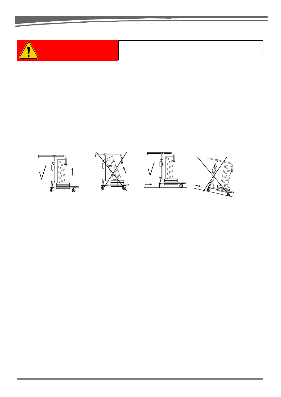
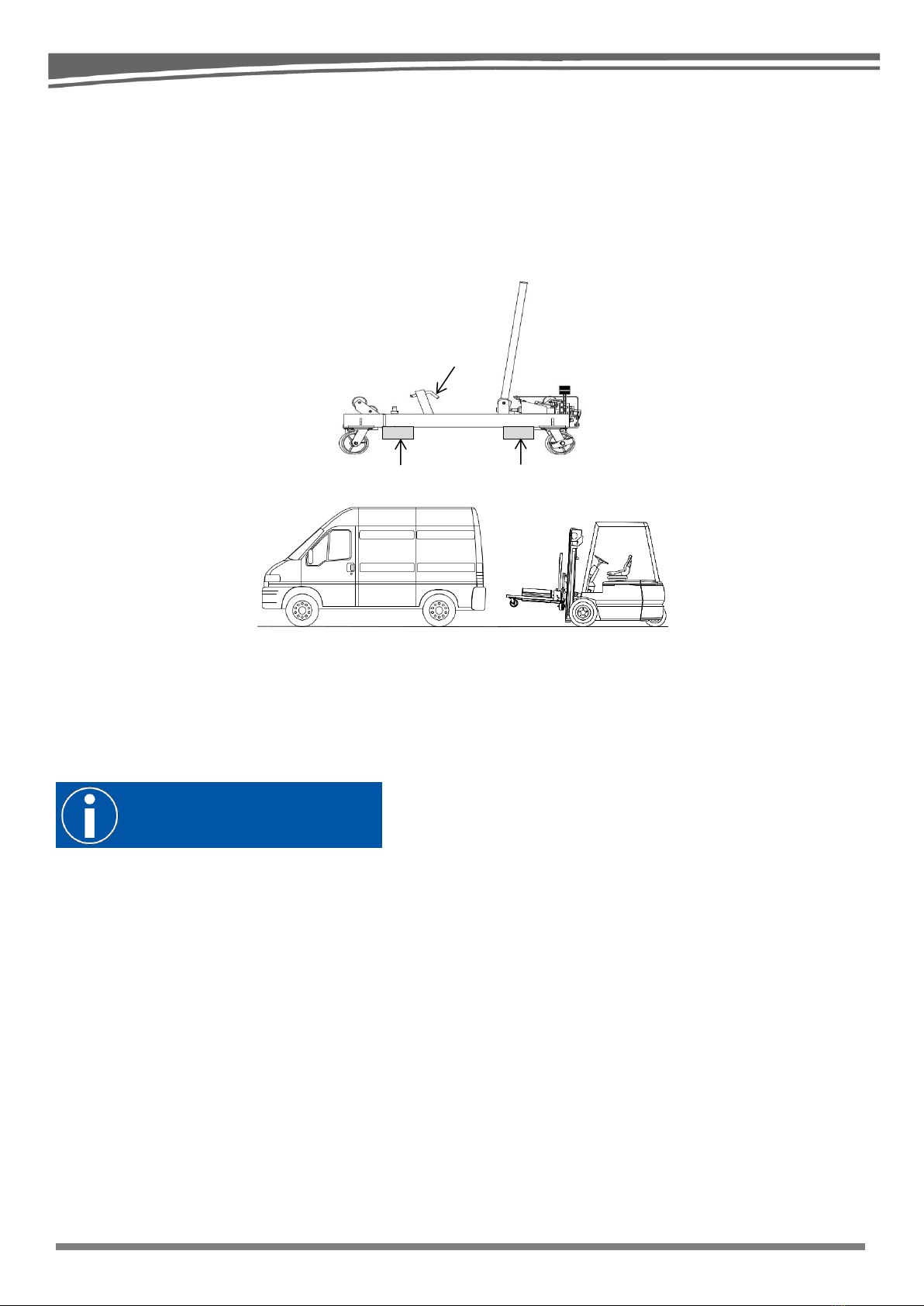
Transporting the WD 1600 Wheel Dolly......................................................................................................................7
Preparation and assembly prior to use ...................................................................................................................7
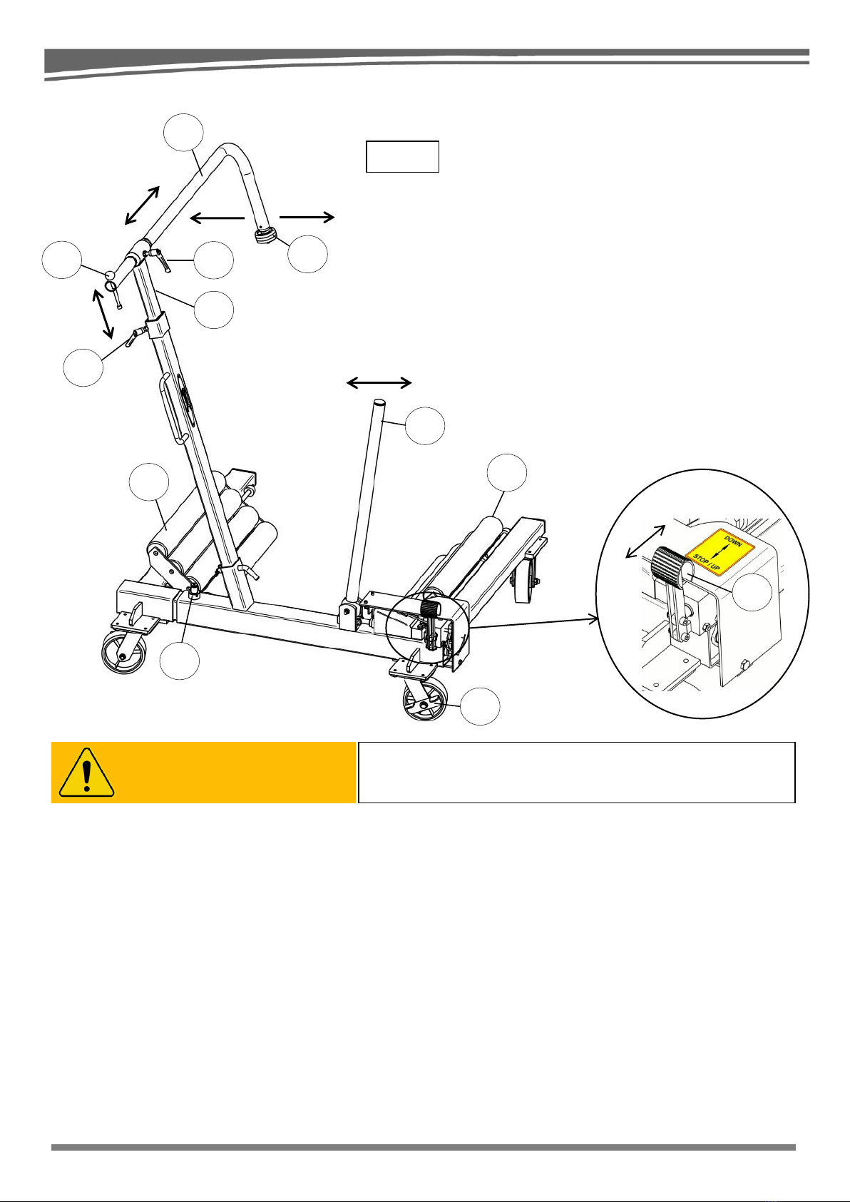
Component overview .....................................................................................................................................................8
Functional description................................................................................................................................................8
Operating instruction......................................................................................................................................................9
Safe operation –Lifting for wheel dismount ............................................................................................................9
Safe operation –Manoeuvring with wheel / load..................................................................................................10
Safe operation –Stopping lowering manoeuvres.................................................................................................11
Safe operation –Lowering for wheel mount..........................................................................................................11
Maintenance instructions ............................................................................................................................................12
General maintenance ..............................................................................................................................................12
Cleaning.....................................................................................................................................................................12
Storage.......................................................................................................................................................................12
Repair.........................................................................................................................................................................12
Oil change .................................................................................................................................................................12
Oil information...........................................................................................................................................................12
Annual maintenance ................................................................................................................................................12
Disposal / destruction ..............................................................................................................................................12
Specifications WD1600 ...............................................................................................................................................13
Periodic maintenance and inspection .......................................................................................................................14
Service Log ...............................................................................................................................................................17
Attached documentation:
CE Certificate
Spare parts list
Assembly Instructions for WD1600
Knowhow is the difference

3
Knowhow is the difference
To the owner / user
Thank you for buying this Compac WD 1600 Wheel dolly.
When correctly used and cared for, this dolly will serve you safely and reliably for many years.
WD 1600 is a mobile lift dolly for mounting and dismounting large wheels with a diameter of 1250 mm to
2400 mm and a total weight of max. 1600 kg.
Read these operating and safety manual before use, to ensure safe use of your new wheel dolly.
On receiving the product, check it for visible damage, cracks or leakage.
Store this operating and safety manual with the wheel dolly at all times.
Compac Hydraulik A/S
Strandhusevej 43
DK-7130 Juelsminde
Denmark
Tel.: +45 75 69 37 22
Fax: +45 75 69 54 18
Web: www.compac.dk
Warranty
Compac Hydraulik A/S provides a 36 month warranty, from the date of purchase, against materials and
manufacturing defects.
Compac Hydraulik A/S disclaims any responsibility for improper use, alterations in construction, use of non-
original parts and repairs and adjustments made by unauthorised personnel.
Compac Hydraulik A/S reserves the right to make changes to the product without notice if this can be done
without significant changes to the technical specifications.
This unit was manufactured in
accordance with the provisions in the
COUNCIL DIRECTIVE OF 2006
(2006/42/EC)
Owner:

4
Knowhow is the difference
Safety
Important: Read and understand the manual before using the product!
All users must read, understand and follow all instructions and safety warnings in this operating manual and
the safety labels placed on the product before using the wheel dolly.
All users must be able to operate the dolly safely and care for it in accordance with this operating manual.
If the user does not understand the language in the manual, it is the owner’s responsibility to furnish a
manual in the user’s language, so the product may be used and cared for according to our instructions.
In case of questions regarding proper and safe use of this wheel dolly, or if you require spare parts, a new
label or operating manual, refer to the contact information on page 3 of this manual or on the product’s
rating plate.
Safety symbols
Safety symbols alert the user of a danger or unsafe use that
will result in serious injury or death.
Safety symbols alert the user of a danger or unsafe use that
can result in serious injury or death.
Information symbols concern general information for the
product’s safe operation, care etc.
READ BEFORE
USE
DANGER
WARNING
INFO

5
Knowhow is the difference
!! This Side:
Install pointing towards pump.
!! Dieser Seite:
In Richtung pumpe montieren.
!! Denne side:
Monteres med retning imod pumpe.
!! Before ending the lifting procedure, turn the safety lock
to activate the manual safety stop.
!! Bevor sie den Hebevorgang beenden, drehen sie die
Sicherheitssperre um den manuellen Sicherheitsstopp zu
aktivieren.
!! Før afslutning af løftet, drejes sikkerhedslåsen for at
aktivere det manuelle sikkerhedsstop.
!! Lock must be open when lifting or lowering the load,
with the small roll supporting the wheel / load on the
opposite side during operation.
!! Diese schloss muss geöffnet sein, beim Anheben oder
Absenken der Last, mit der kleinen Stütz Rolle auf die
andere Seite des Rades / Last während des Betriebs.
!! Låsen skal være åben under løft eller sænkning
af lasten, med den lille rulle understøttende hjulet / Lasten på
modsatte side under drift.
Safety and information labels that are required on the wheel dolly
WD 1600 Label reference.
6
8
7
6
6
6
5
3
4
2
1
8
7
5
2
1
3
S
4
L

6
Knowhow is the difference
General safety
•Never make any alterations in the product’s construction.
•Do not use damaged or altered equipment.
•Inspect the general condition of the dolly before each use.
•Check for breaks, cracks or bent parts, loose or missing parts, and any other condition that could affect
the proper and safe function of the product.
•Before use, check the dolly thoroughly. If the dolly does not appear to be working correctly, follow the
instructions in the section: Periodic maintenance and inspection.
•The wheel dolly is a tool designed only to mount and dismount wheels on a vehicle that is already been
lifted and supported by a trestle and must not be used as an independent tool for lifting vehicles.
•Do not lift the horizontal or vertical arm, as these are only designed to support the wheel.
•Use the unit on a horizontal, even and solid surface in a well-lit area.
•The wheel/load should be lifted vertically, as the load might otherwise slide out at the bottom and away
from the unit. This can cause the wheel dolly to “shoot out” toward the user.
•Do not use the unit to lift more than 1600 kg.
Failure to observe the max. lifting capacity could cause serious injury or damage to property.
•Lowering a load of over 1600 kg onto the unit could result in significant damage to the wheel dolly. This
could happen, for instance, if you lower the vehicle before the user has lowered and removed the wheel
dolly after use with the vehicle.
•Users and others must keep a safe distance of at least 0.5 m from the load.
•The unit must not be used if it is leaking oil or if the unit is functioning in a way that is different from the
description in the operating instruction. If this is the case, stop using the dolly immediately and contact
an authorised service technician for inspection and, if needed, repair of the unit so that it may be used
safely again.
•Make sure that warning and information signs on the product are legible and intact at all times.
•Never perform service on the dolly while it is carrying a load.
Further updated safety information is available at www.compac.dk under “Service”.
Failure to observe the following will result in serious bodily
injury or death, as well as damage to property.
DANGER

7
Knowhow is the difference
Transporting the WD 1600 Wheel Dolly
The WD 1600 Wheel Dolly is a mobile unit that is very versatile and can be transported to the service
location in a van, securely fastened to it.
Due to the dolly’s tare weight, there is a risk of injury. Therefore, it is strictly necessary that loading of the
dolly into the vehicle is done with a stacking truck or forklift by staff with the necessary operating permits.
The tower with the horizontal and vertical support arm can be removed by pulling out peg (C) for transport.
The forklift or stacking truck’s forks should be driven to the back of the frame and positioned at point (D) for
proper lifting.
Preparation and assembly prior to use
Read and understand the enclosed operating manual before use.
On receiving the product, check it for visible damage, cracks or leakage.
Installation / assembly of the unit: See the attached assembly instructions for the WD 1600 Wheel Dolly.
C
D
D
INFO

8
Knowhow is the difference
2b
2a
E
A
W
M
K
H
P
F
F
L
S
Fig. 1
N
Component overview
Functional description
The wheel / load is lifted with the help of 2 x 4 lifting rollers (F), which are pressed in underneath the wheel
from both sides. The rollers can be adjusted to the width of the wheel by sliding a strong mandrel. The
adjustable support arm (A) keeps the wheel securely balanced, ensuring stability during handling.
To lift the wheel, move the change-over valve (E) into the lifting position (2b) and pump with the pumping
rod (P). The lifting cylinder positioned inside the frame now pulls the frame with the rollers (F) towards the
wheel, thereby lifting the wheel. A lift will always be heavier in the beginning.
To lower the wheel, move the change-over valve (E) to the lowering position (2a); the wheel will now slowly
lower. If the wheel does not lower automatically, it must be lowered by pumping the pumping rod (P). The
cylinder placed inside the frame now pushes the frame with the rollers (F) away from the wheel, thereby
lowering the wheel.
The frame has a mechanical safety lock (S) which, when activated, ensures that the rollers will not glide
away from each other, even in the event of a hydraulic error.
The pumping rod (P) has a double function; in addition to its pumping function, it is used to manoeuvre the
wheel dolly.
The wheel dolly is fitted with a wheel brake on the back transport wheels, which can be used to brake the
unit.
Pos.
Name
A
Horizontal support arm
E.
Change-over valve
F
Lifting roller
H
Vertical telescopic arm
K
Handle for support arm (A)
L
Lock for telescopic arm (H)
M
Lock for support arm (A)
N
Wheel lock
P
Pumping rod
S
Stabilizer safety lock
W
Support roller
To brake / stop lowering of the wheel / load, set the change-
over valve (E) to the STOP position (2b).
WARNING

9
Knowhow is the difference
Operating instruction
The wheel dolly must be positioned on a horizontal, level, dry and stable surface.
Before lifting a wheel, the vehicle must be lifted so the wheel is lifted completely from the ground, and the
vehicle must be secured / supported properly with an approved support (se Fig. 2).
The lock (L) must always be open during lifting and lowering, so the vertical telescopic arm (H) with the
horizontal support arm (A) and support wheel (W) can support and follow the wheel at all times (See Fig. 2).
Safe operation –Lifting for wheel dismount
The following letter designations refer to the component overview on page 8.
1. Move the wheel dolly over to the lifted vehicle and the wheel to be lifted.
2. Place the rollers (F) on each side of the wheel to be lifted. Move the unit as far forward against the
wheel as possible.
3. Loosen the lock (L) and raise the telescopic arm (H) vertically, so the horizontal support arm (A) can go
in over the wheel. Retighten the lock (L).
4. Loosen the lock (M) and the horizontal support arm (A), grip the handle (K) and place the arm (A) so it
can go in over the wheel and under any existing mudguard. Retighten the lock (M).
5. Move the wheel dolly in under the wheel as close to the wheel as possible.
6. Loosen the lock (M) and grip the handle (K). This allows you to push the horizontal support arm (A) with
the support roller (W) between the wheel/load and any existing wheel mudguard.
7. When the roller (W) is on the other side of the wheel, turn it down, to support the wheel/load on the
opposite side. Pull handle (K) back while tightening the lock (M).
8. Now the wheel/load can neither fall forward toward the user or away from the user.
CONTINUED ON NEXT PAGE!
Failure to observe the following will result in serious injury
or death, as well as damage to property.
K
W
E
P
L
F
H
A
M
Fig. 2
Failure to observe the following may result in serious injury
or death, as well as damage to property.
The lock (L) must always be loosened during lifting and lowering so the vertical telescopic arm (H) with
the horizontal support arm (A) and support wheel (W) can move freely and thereby support the
wheel/load at all times, including during lifting and lowering. Otherwise, the wheel/load could fall out of
the wheel dolly and potentially cause damage.
DANGER
WARNING

10
Knowhow is the difference
9. Loosen the lock (L) so the vertical telescopic arm (H) can move up and down during lifting and
lowering.
10. Lift the safety lock (S) and turn it so it stays up (See Fig. 3)
11. Pull out the change-over valve (E) to position 2b (See Fig. 1)
12. The unit is operated by setting the change-over valve (E) to one of two positions (position 2b for lifting
and 2a for lowering) and pumping with the pumping rod (P).
13. Pump using the pumping rod (P) until the rollers (F) are touching the wheel on both sides.
14. You can now lift the wheel.*
* Before completing the lift, turn the safety lock (S) so
that the split pin through it is aligned with the two grooves
in the hub. This is a manual safeguard.
After a short lift or lowering, the lock will activate, and,
therefore, the load can neither be lifted nor lowered.
To release the lock, pump gently in the opposite direction
to allow deactivation of the lock (pulling out).
Safe operation –Manoeuvring with wheel / load
The following letter designations refer to the component overview on page 8.
Before operating the unit with the wheel/load, make sure that the support roller (W) is correctly positioned
and tightened via lock (M) and lock (L), both in a secured position, and that the safety lock (S) is in the
locked position.
Failure to observe the following may result in serious bodily
injury or death, as well as damage to property.
The lock (L) must always be tightened during transport with the wheel, so the vertical telescopic arm (H)
with the horizontal support arm (A) and support wheel (W) cannot move and thereby support the
wheel/load. Failure to do so could result in the wheel/load falling out of the wheel dolly and potentially
causing damage. For heavy loads or uneven surfaces, two persons are required to push the dolly, to
prevent undue strain on the arms, back or other body parts.
WARNING
Fig. 3
S
Activated
(locked)
Deactivated
(Unlocked)
Split

11
Knowhow is the difference
Safe operation –Stopping lowering manoeuvres
Safe operation –Lowering for wheel mount
The following letter designations refer to the component overview on page 8.
1. Move the wheel dolly, with the wheel in the lifted position, to the vehicle, and centre it horizontally next
to the vehicle’s wheel hub.
2. Before lowering, make sure that the lock (L) is not locked and that support roller (W) is gripping the load
on the opposite side of the wheel.
3. Lift the safety lock (S) and turn it so it stays up (See Fig. 3).
4. Lowering of the load is controlled by using your foot to push the change-over valve’s (See Fig. 4) foot
pedal (E) into the lowering position 2a (DOWN), which lowers the wheel. If the wheel does not lower
automatically, it may be necessary to use the pumping rod (P) and pump it down.
To STOP lowering entirely, the foot pedal (E) must be set to position 2b (STOP/UP). The lowering
speed can be adjusted by moving the foot pedal (E) slowly in the direction of 2a (DOWN).
Important: The wheel must be lowered to just below the desired height.
5. Now set the change-over valve (E) to the lifting position 2b (STOP / UP) and use the pumping rod (P) to
pump until the wheel is at the correct height for mounting.
6. Move the wheel dolly with the wheel facing/over the wheel hub so the wheel bolts can be mounted, and
mount the wheel.
7. Loosen the lock (L) and lift the vertical telescopic arm (H) so the horizontal support arm (A) can move
freely over the wheel, then tighten the lock (L).
8. Loosen the lock (M), grip the handle (K) and turn the horizontal support arm (A) so it does not hit the
wheel, then retighten the lock (M).
9. Set the change-over valve (E) to the lowering position 2a (DOWN) and pump using the pumping rod (P)
until the wheel is no longer touching the rollers (F).
10. Pull the wheel dolly away from the vehicle, turn the horizontal support arm (A) vertically and tighten the
lock (M) and lock (L) for proper storage.
11. Move the wheel dolly to storage and lock the back transport wheels (N) for safe storage.
Failure to observe the following may result in serious bodily
injury or death, as well as damage to property.
After the safety lock (S) has been deactivated and the pedal (E) for the
change-over valve set to the lowering position 2a (DOWN), a large load
on the rollers can force an AUTOMATIC lowering.
To STOP this MOVEMENT, the user must be ready to use their foot to
move the pedal (E) to pos. 2b (STOP/ UP).
This stops the movement immediately.
Failure to observe the following may result in serious bodily
injury or death, as well as damage to property.
The lock (L) must always be loosened during lifting and lowering so the vertical telescopic arm (H) with
the horizontal support arm (A) and support wheel (W) can move freely and thereby support the
wheel/load at all times, including during lifting and lowering. Otherwise, the wheel/load could fall out of
the wheel dolly and potentially cause damage.
WARNING
WARNING
Fig. 4
2b
2a
E

12
Knowhow is the difference
Maintenance instructions
General maintenance
Follow this maintenance instruction, to preserve the wheel dolly’s safety, performance and service life.
•All moving parts must be inspected, cleaned and lubricated once a month using a moisture-displacing
lubricant.
•Check the wheel dolly for oil leaks and call an authorised service technician if required.
•In case of rust, remove the rust and protect with a rustproofing agent.
•Check that locks and rollers on the unit (M, L, S, F and W) are all intact and working properly.
•Check that retaining rings, nuts, bolts, and mandrels are intact and working properly.
Cleaning
Ordinary cleaning with mild soap (i.e. dishwashing detergent, auto shampoo) and a soft brush.
Thorough drying will protect the dolly’s painted surfaces.
Never wash the dolly using a high-pressure cleaner, as this may damage the dolly’s surface and
components.
Storage
The dolly should always be stored in vertical position in a dry and temperate climate.
Repair
In case repair of the dolly is required, use only original Compac parts.
This work must be done by a qualified hydraulics specialist.
Use of non-original parts not supplied by Compac could make the dolly unsafe for use and nullifies the
warranty.
Oil change
If it becomes necessary to refill oil in the double-acting cylinder, see the section “Periodic maintenance and
inspection” in section 3, and follow the instruction for action 3A.
Oil information
Replace the oil as needed or at every 1 - 2 years.
Oil type: Castrol Hyspin AWS 22 or similar hydraulic oil with the same specifications.
Do not use brake fluid, motor oil or the like!
Annual maintenance
A specialist must perform an annual safety inspection, where the following is checked:
•All hydraulic components must be checked for leaks.
•The frame, rollers and pump must be checked for wear, cracks and other damage.
Disposal / destruction
Re-use the transport packaging if possible, or bring it to a recycling centre.
For service, repair or disposal of the wheel dolly, drain the oil into an approved container and bring it to the
proper authority. For disposal of the wheel dolly, bring it to a recycling centre.
INFO
RECYCLING

13
Knowhow is the difference
Specifications WD1600
Dimensions and weight:
Width x Depth x Height (Operation): 2081 mm x 1280 mm x 2479 mm
Width x Depth x Height (Transport): 1362 mm x 1280 mm x 1150 mm
Weight: 161 kg
Capacity:
Handling of wheels with a diameter 1250 mm to 2400 mm
Handling of wheels with a width Max.1050 mm
Max. lifting capacity: 1,600 kg
Oil information:
Oil content: 0.6 Liter
Oil type: Castrol Hyspin AWS 22 or corresponding
hydraulic oil with the same specifications.
Min. 190
Max. 1080
Min. 695
Max. 890
Min. 1362
Max. 2081
1280
Min. 1564
Max. 2479
Min. 95
Max. 290
1150
Maximum 1050 mm
Min. 1250 mm
Max. 2400 mm

14
Knowhow is the difference
Periodic maintenance and inspection
Wheel Dolly WD 1600 (1600 kg)
Model WD 1600 from 01-01-2018 and later
Only persons certified in professional repair and maintenance of hydraulic equipment may perform the
following risk assessment and annual maintenance of Compac wheel dolly.
Use only original parts from Compac.
Risk assessment for the wheel dolly –annual inspection or in case of malfunction.
1. Identify wheel dolly
(Confirm capacity / year and month of manufacture)
Drawings with spare part numbers are available for current and older types on our website:
www.compac.dk, where you will find more information under: service and the section on spare parts.
If the products are not from the current assortment (catalogue models), please see under “Old models”.
For these, too, only original parts from Compac should be used, to maintain safe and reliable operation of
the product.
2. Test equipment
Use the following to make a risk assessment.
A wheel with a tare weight of 1,600 kg. An ideal setup is a wheel that is hanging vertically and standing on
the floor, hanging from an authorised crane, where the wheel is secured against falling/rolling forward,
backwards or sideways. In case of malfunction of the wheel dolly during testing, the wheel is secured
against causing injury or material damage.
3. Visual inspection
Check that the oil level in the oil tank is correct.
Action 3A: The correct amount of oil is 60 mm, measured from the bottom
of the oil tank. Never overfill the oil tank. To fill oil in the double-acting
cylinder, lift the front cover on the change-over valve, where the filling
plug is located at the top of the tank. Use the pump rod to pump the oil
into the cylinder and to get any air out of the system. Make sure to pump
the frame out into the widest position and then back to the narrowest
position before filling, and fill the correct amount of oil.
Replace the oil plug and the front cover, and dry the area with a clean cloth before use.
Use only hydraulic oil Castrol Hyspin AWS 22 or similar with the same specifications.
Do not use brake fluid, motor oil or the like, as these may damage the dolly’s internal components.
Check of retaining rings and bolts
Action B: If a retaining ring or bolt is missing, rusty or not 100% intact: clean the spot where the retaining
ring / bolt was located and replace the ring with a new one.
Is there any visible leakage of oil from the wheel dolly?
Action 3C: Place the wheel dolly under the test wheel and look for leaks by placing the wheel dolly under
pressure.
Look for leaks in the cylinder, pump and hydraulic pipes and hoses. If leaks are found, replace the defective
parts with new original parts.
Is there any visible rust?
Action 3D: In case of visible rust, strip the damaged parts so it is possible to determine whether the rust has
reduced the strength of the affected parts. If so, replace the part with a new part.
Before installing the new part, make sure the part has been lubricated or that the surface coating of the part
is intact.
Are there any visible cracks in the welding?
Action 3E: If the wheel dolly has visible cracks in the structure or welds, the dolly must not be used until the
error is properly remedied. If it is possible to replace the part, do so before use.
60 mm

15
Knowhow is the difference
Are there any visible cracks in the paint covering the welds?
Action 3F: In case of visible cracks in the paint, place the wheel dolly under controlled pressure –at nominal
capacity.
At this pressure, check whether the cracks expand.
If so, it shows the same defects as described in 3D.
The solution is the same as 3D. If the paint’s cracks do not expand, the problem is only superficial.
Do the transport wheels on the wheel dolly rotate freely; are the wheels still round and without cracks?
Action G: If one of the three problems arises, replace the wheels with new wheels. Make sure that the axle
for both the front and back wheels is well greased.
Is the wheel dolly so dirty that some of the parts are not working properly?
Action 3H: Carefully clean the wheel dolly and especially the moving parts. If cleaning with soap and water,
all moving parts must then be greased well before use.
Never wash the dolly using a high-pressure cleaner, as this may damage the dolly’s surface and
components.
If the handle for pumping and the pedal for switching direction working?
Action 3J: The pumping rod and change-over valve system are manually operated. Make sure that
movements with the pumping rod are driving the hydraulics. To check the change-over valve, actuate the
valve’s pedal and make sure that its switching and subsequent movements with the pumping rod drive the
hydraulics as desired.
Does the lifting roller look robust and intact?
Action 3K: The rollers should have a flat, uniform and rust-free surface with no dents, and they should roll
easily without a load. Replace any roller that does not comply with a new roller.
Does the safety lock look intact and work properly?
Action 3M: The safety lock must be clean, rust-free and work exactly as described in operation. If not,
replace it with a new lock.
Are all safety labels present as indicated in the label overview?
Action 3N: In case of any missing or damaged safety label, contact Compac to purchase a new label.
4. Testing and adjustment
Pump the wheel dolly together with NO LOAD. If the wheel dolly cannot be pumped together entirely -
check the oil level (See action 3A) or check for any foreign objects that may have become lodged in the
dolly and which are preventing the moving parts from moving normally.
Pump the wheel dolly out to its maximum width again. If you are unable to do this, the dolly may require oil.
Check the oil level and fill if necessary, or check for the presence of grime or foreign objects that are
preventing the dolly from reaching its maximum width.
Testing the hydraulic system under pressure
Place the wheel dolly in a testing device (See item 2 “Test equipment”).
Build up pressure by pumping the lifting roller around the load until it is off the floor.
Let the dolly stay under this pressure for two minutes.
After two minutes, if there is still pressure of at least 500 kg, the return system is air-tight and functioning
properly.
(There are no leaks in the hydraulic system). Release the pressure by pumping back.

16
Knowhow is the difference
Calibrating the dolly.
If the unit is to be calibrated, the load must be 1,600 kg. The lifting capacity must be set on point *A1.
(See Fig. 5) using a screwdriver.
Setting: With a load of 1,600 kg in the unlifted position, turn *A1 two rotations backwards (or out of thread)
and then try to lift the 1,600 kg load. If it is possible to lift the load, lower it again and screw one rotation
outwards and repeat the attempt until the dolly can NOT lift the load.
When you reach this point, screw *A1 one rotation forward (into the thread), and the capacity is then set to
be between 1,600 and 1,650 kg!
Adjusting the lowering valve.
If it is not possible to calibrate the lifting capacity, try to turn the mandrel (B) (See Fig. 5) one full rotation
clockwise, to adjust the lowering valve.
You may have to repeat this step several times. (Note: Max. three rotations.)
Inspecting the frame and lifting arm under pressure
While the dolly is fully loaded –please check carefully for errors –as described in 3 A-F.
In case of error, make the necessary adjustments/repairs. Do this before moving to the last part of
inspection.
Stop test.
The stop test is performed to check the change-over valve (E) (See Fig. 1).
Place the wheel dolly in a testing device (See item 2 “Test equipment”).
Lift the wheel until it is at least 10 cm above the floor by following the
instructions in the section (“Safe operation – Lifting for wheel dismount” in this
manual).
Lower the wheel, stopping periodically, to check the change-over valve’s
closing mechanism. See the sections “Safe operation – Stopping the lowering
movement” and “Safe operation – Lowering for wheel mounting”.
If lowering of the wheel does not stop immediately when you set the change-over valve to lifting position 2b,
the change-over valve (E) must be replaced.
The test is now complete, and the wheel dolly is calibrated.
When the test is complete and the dolly is ready for use
Fill in the Service Log in the operating manual with the following: service date, name / stamp of service
technician, and date of next service.
Next, complete the Certified Periodic Maintenance form, and stick it on the wheel dolly, making the
authorisation visible for the user.
Setting the dolly to a capacity greater than the max. capacity
(1,600 kg) can result in injury and property damage, as the
dolly is only built for a max. capacity of 1,600 kg.
B
*A1
Fig. 5
DANGER
2b
2a
E

17
Knowhow is the difference
Service Log
Operating manual WD1600 (GB) V.2 / Compac 2018 / lvm
Date
Performed By
Other Business
Next Service
D/M/Y
Stamp or signature
-
D/M/Y
Table of contents
Other Compac Outdoor Cart manuals
Popular Outdoor Cart manuals by other brands

Costway
Costway GT3451 user manual

Costway
Costway KC55044 manual

Office Star Products
Office Star Products OSP Designs WIL4160 Assembly instructions

Seville Classics
Seville Classics WEB234 quick start guide

Doherty
Doherty Howarth 01 Instructions for use

Powerfix Profi
Powerfix Profi 275105 quick start guide