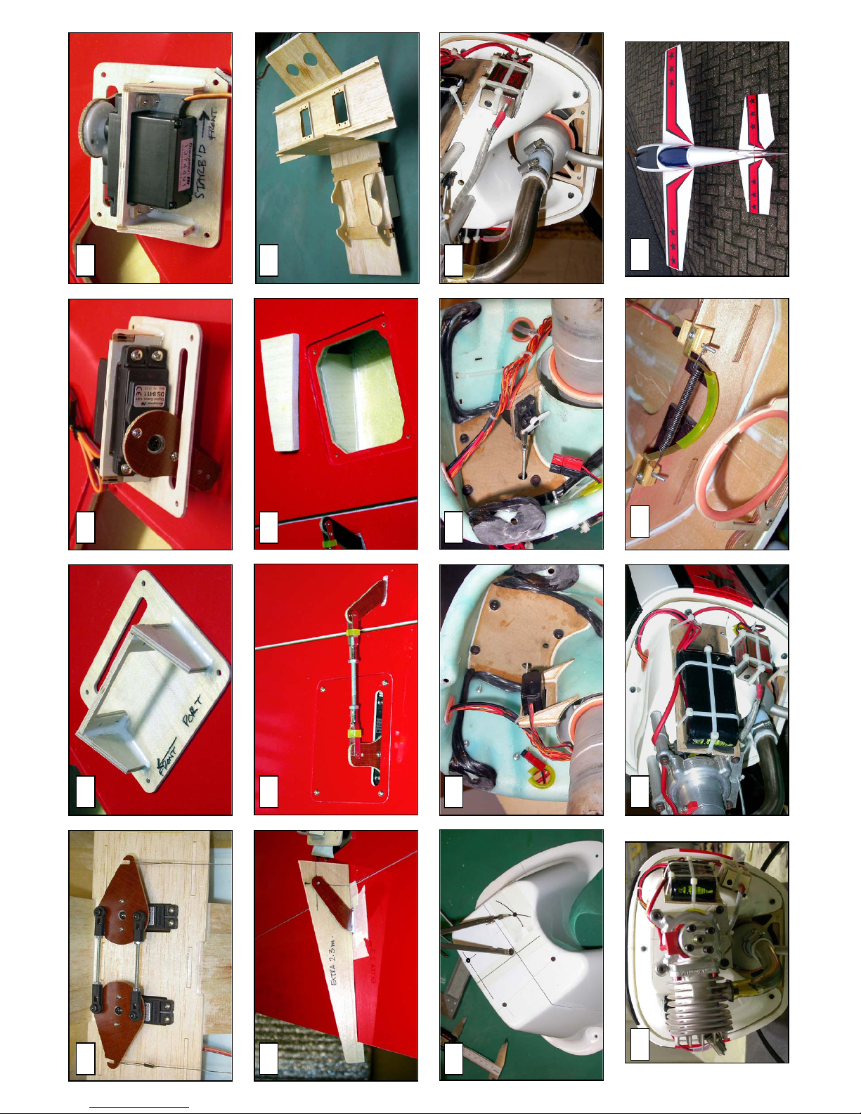
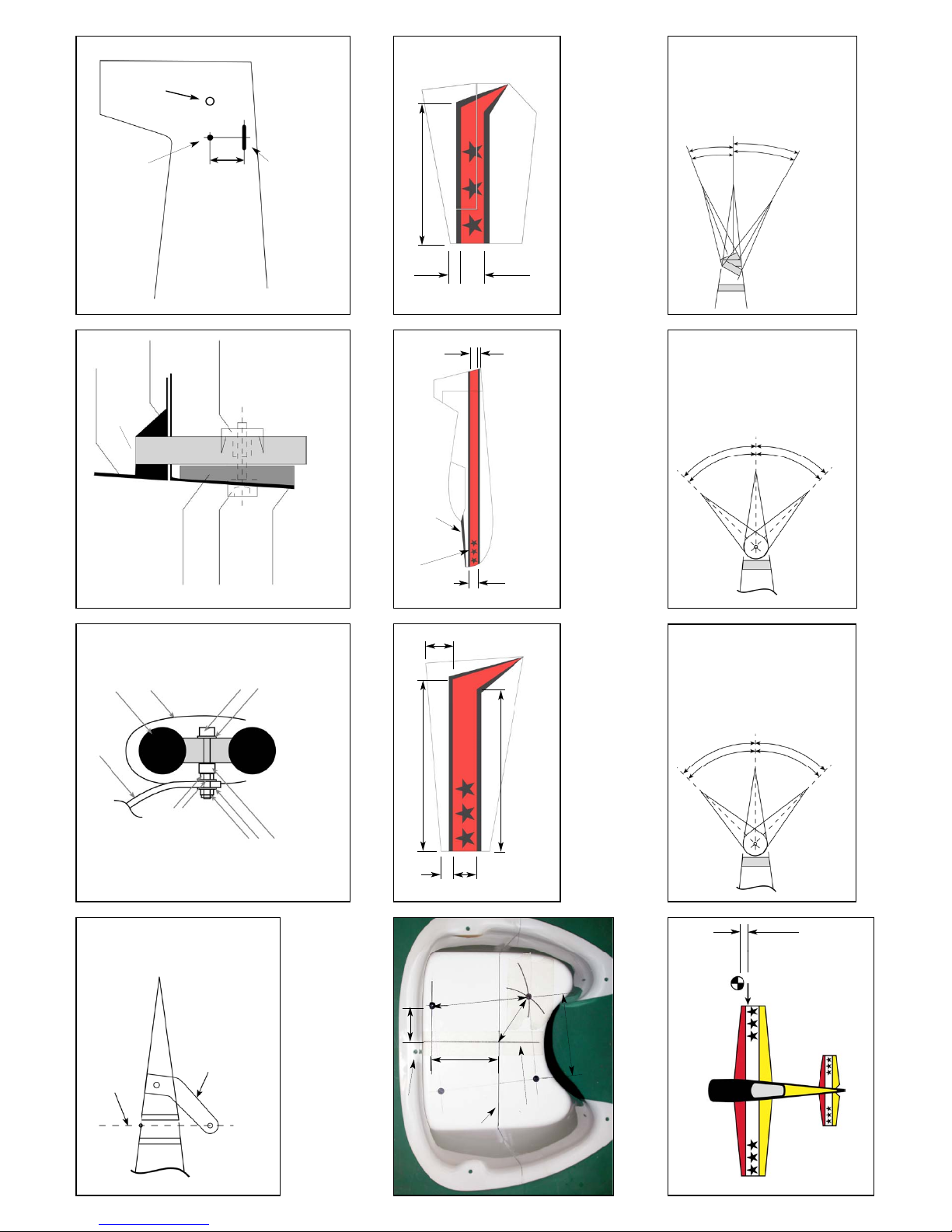
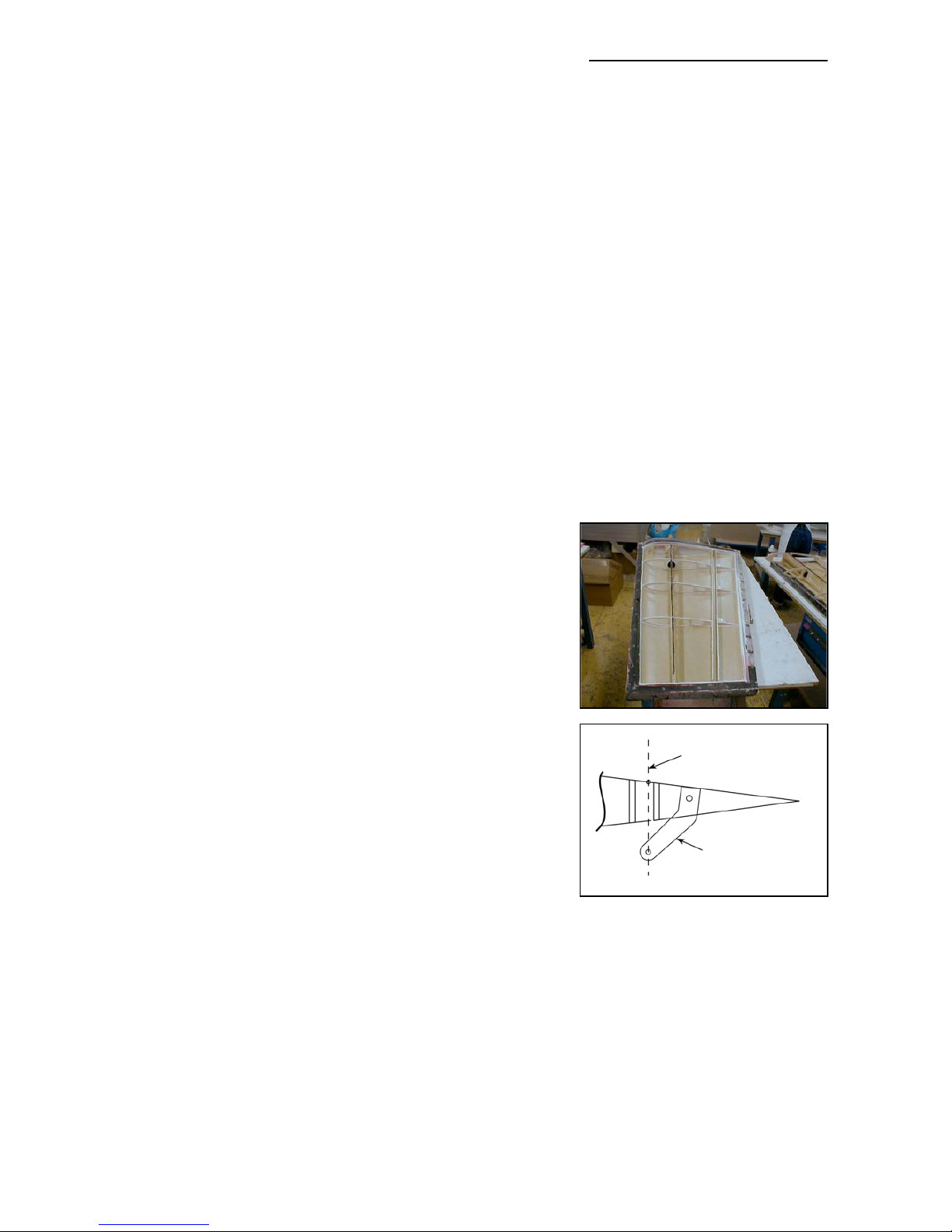
Make sure that the control horns are glued into the ailerons properly. The hole in the phenolic
horn for the quick-link needs to be exactly perpendicular to the hinge axis line, and in this
manual we show you a simple way to ensure that the horns in all pairs of control surfaces will be
identical, making it easy to set up your R/C for accurate flying manoeuvres.
For normal pattern flying one good servo for each aileron is enough, but if you want to do more
radical 3D manoeuvres, then fit 2 servos per aileron. We have supplied the extra 2 servo mounts
for you in the kit - all you need to do is cut out the servo cover hatches that are marked on the
bottom surface of the wing, and construct in the same way as the standard inner servo mounts.
The result is a rock solid servo mount and linkage, but still easy to maintain or exchange.
The wings are attached to the fuselage using the 4 threaded aluminium dowel anti-rotation pins,
with 4 plastic nuts inside the fuselage. If the aluminium dowels come loose in the wing, the wing
will slide outwards, away from the fuselage, and the main spar will definitely break. So take great
care to inspect the glue joints of these anti-rotation dowels in the wing REGULARLY. Excessive
vibrations or hard shocks can cause the glue joints to weaken or break. Monitor these joints
whenever you set up your plane. Never forget to tighten the nuts inside the fuselage. Your flight
will end after 100 ft and you will have to fix a hole in your club’s runway. Please DO NOT
modify these attachment dowels in any way, their perfect function is proven for many years.
The Fuselage:
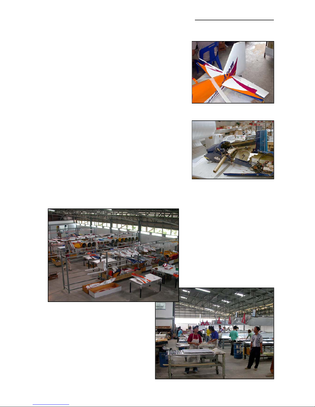
The fuselage is also made in negative moulds, and (except for the bottom surface) it is also all
constructed using TAVS technology. All the loadbearing internal parts are glued in during manu-
facture, to ensure accurate location and reduce the assembly time for you. The sleeves for wing
and stab spar tubes, and the holes and reinforcement plates for the anti-rotation dowels, are
already installed. There is no need to even check the incidences - you can be assured that these
are already set in the moulds so that no adjustment is necessary.
The landing gear mount is strong and doesn’t need any extra reinforcement. You have an
extremely light weight fuselage, and the gear loads need to be led into the structure gently. No
glue joint needs to be stronger than the materials that it is attached to, as it would just result in
increased weight for no advantage. The landing gear is a fairly flexible design, which works very
much like shock absorbers. This plane is not made for crashing, but the landing gear will take
some hard landings without problems. Do not change or modify it, as the results would only be
negative. We had plenty of time and experience to engineer the strength needed in this area -
and we did !
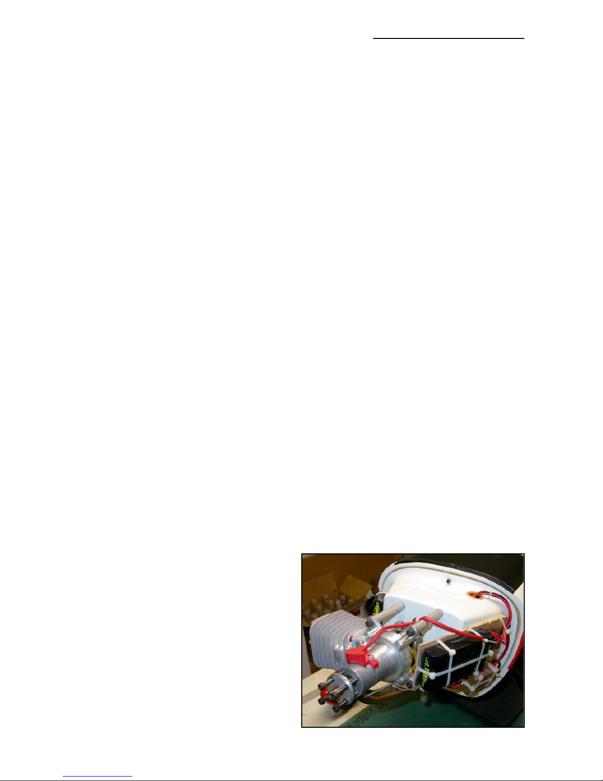
The firewall is preinstalled, and provides
plenty of strength for up to any 75 cc
engines on the market today. The mounting
holes in the firewall are are pre-drilled dur-
ing manufacture, and the corresponding
holes that you need to drill in the moulded
motor dome are marked for you in the
mould for the greatest accuracy. See the
Engine Installation section for adjusting the
mount and setting thrust angles.
The engine cowling and canopy frame
should be attached using the method
shown here. This is only a little work and all
suggested mounts are tested and proven
for many years.
6