Compur Statox 506 User manual

1
Getting started with the Statox 506
1 Safety Instructions
Statox 506 is a transmitter designed as an intrinsically safe device, group 2 category II. It measures the
concentration of toxic gases and oxygen in ambient air. It is safe to be operated in classified areas zone 1
and zone 2.
The gas specific parameters are stored in an F–Ram on board of the sensor. They will be downloaded
into the sensor head electronics automatically as soon as the sensor is plugged in.
Safety advice:
Read and observe this manual carefully. Keep it in a safe place.
This transmitter must be installed and connected observing the regulations for operation in hazardous
areas. It must be performed by authorized and trained personnel only. Respect the regulations for the
operation of safety instrumented systems including standard DIN EN 60079-14.
If operated in a hazardous area, the sensor head power supply must run through an intrinsically safe
repeater or the loop itself must be intrinsically safe, see chapters 3.1 and 3.2.
Potential equalization must exist along the intrinsically safe circuit.
Statox 506 must not be operated in an ambience outside the technical specifications, see chapter 8.
Statox 506 must be operated and serviced by authorized and trained personnel only. Use only original
Compur parts as spares and consumables.
Do not operate uncomplete or damaged sensor heads.
All of the above warnings must be observed. Incorrect installation or connection will void the
explosion proof rating and thus be dangerous to human life and assets.
This instruction is for quick orientation!
Prior to installation and operation please download and
read the detailed manual. Manuals in several languages
are accessible on our homepage www.compur.com.

2
2 Installation
Loosen the 4 captive screws. Put the cover on a clean place. In order to ease installation, the flat cable is
not connected ex works.
Connect the ground contact to ground. It can take cables up to 4 mm². Reassure proper grounding.
Please find more installation instructions in the detailed manual on our homepage www.compur.com !
Fasten the housing to the wall.
Screw specs: Ø ≤4.5 mm, head Ø ≤6.9 mm.
Install in an upright position with the sensor downwards!
Avoid ingress of dust or humidity.
Connect the cable as shown in chapter 3.
Connect the cover to the pcb with the flat cable. The plug is
mechanically coded.
Fasten the cover.

3
3 Electrical Connection
If installed in a classified area, the power supply must run through an intrinsically safe repeater.
The combination Sensor head / repeater / cable must be within these parameters:
Specifications:
Uo, Io, Co, Lo :Approved repeater specifications.
Ui, Ii, Ci, Li: Approved sensor head specifications (Technical data)
CL = Cable capacity in nF/km
LL = Cable inductivity in nH/m
l = Cable length in m
The allowable cable length must be calculated from the cable capacity and the inductivity of the sensor
head with this formula: lmax = (Co- Ci) / CL
Recommended cable:
2 x or 3 x 0.5 mm², preferably shielded (e.g. LiYCY).
Terminals: 0.25 –2.5 mm² (AWG 24 - 12).
The cable gland can accept cables from 4 to 12 mm outer diameter.
Advantage of 3 wire operation:
The signal in the error mode must always be 2 mA when operating in 2 wire installation in order to assure
enough power for the operation.
If you install the sensor head with a 3 wire cable, you can set the current in the error mode to 0 mA. Then
you can set the current in the service mode to 2 mA and thus differentiate between system failure (critical
error) and service mode (non - critical error).
If you operate the Statox 506 sensor head directly on a PCS, use the following diagram.
In case of 2 wire operation use terminal 1 and 2.
V+
0V
2-22mA
I=0mA
1
2
3
Caution:
First complete the electrical connections, then plug the sensor in.
Please find more instructions in the detailed manual on our homepage www.compur.com !
Sensor
Statox 506
PCS
Uo ≤Ui
Io ≤Ii
Co≥ Ci+ l .CL
Lo ≥ Li+ l .LL
Example:
Cable type LiYCY 0,75mm² : CL = 150 nF/km
Repeater: Co = 705 nF
Sensor head: Ci = 24 nF
lmax = 4540 m

4
3.1 Connection Diagram with Statox 502/503 Control Module in the 2-Wire Mode
Before connecting the Statox 506 to a Compur Statox 502 or Statox 503 Control Module, the appropriate
program in the control module must be set. The programs are listed in the operation manual of the control
module.
3.1.1 2-wire mode installation in non-hazardous areas
3.1.2 2-wire mode installation in hazardous areas
Caution:
The input / output terminals may be different for
different intrinsically safe repeaters. Wrong
connection might destroy the repeater and / or the
control module. Avoid short–circuits and wrong
polarity!
The terminal numbers at the repeater refer to
model 9160/13-11-11 from R.Stahl, Waldenburg
(Siemens 7NG4124-0AA00). It needs an own
power supply and operates as current source at
terminals 1 and 2.
Do not operate control module and repeater on
the same bus –the polarity is different!
Non-hazardous area
Hazardous area
Power
supply
Power
supply

5
3.2 Connection Diagram with Statox 502/503 Control Module in the 3-Wire Mode
Before connecting the Statox 506 to a Compur Statox 502 or Statox 503 Control Module, the appropriate
program in the control module must be set. The programs are listed in the operation manual of the control
module.
3.2.1 3-wire mode installation in non-hazardous areas
3.2.2 3-wire mode installation in hazardous areas
Caution:
The input / output terminals may be different for
different intrinsically safe repeaters. Wrong
connection might destroy the repeater and / or the
control module. Avoid short–circuits and wrong
polarity!
The terminal numbers at the repeater refer to
model 9160/13-11-11 from R.Stahl, Waldenburg
(Siemens 7NG4124-0AA00). It needs an own
power supply and operates as current source at
terminals 1 and 2.
Do not operate control module and repeater at
the same bus –the polarity is different!
Non-hazardous area
Hazardous area
Power
supply
Power
supply

6
4 Control Elements and Display
The display is an 8 digit 14-segment-LCD.
You can program the sensor head by holding the magnetic pin on the control buttons:
Symbol
Name
Function
Right
Increase value.
Navigate to the right.
Push and hold the contact for speed mode.
Left
Decrease value.
Navigate to the left.
Push and hold the contact for speed mode.
Reset
Navigate backwards.
Change entry.
Enter
Main menu.
Confirm.
5 Start up
After connecting the sensor head to power, it performs a self–test and after a few seconds displays
the software index.
Remove the yellow protection cap from the sensor cover.
Install the sensor and the dust filter which is included in the sensor package.
After the sensor has been plugged in, the sensor head reads the sensor parameters and displays the
parameter set index, the target gas, the measuring range and the best-before date of the sensor in the
format week / year. After zero has stabilized, the sensor head goes into the measuring mode.
If you plug in another sensor type as before, the display shows NEW TYPE. Confirm this with ENTER.
Otherwise remove the sensor and plug in the right type.
As long as the sensor head has not gone into the measuring mode, it is in the ERROR mode.
(0 mA signal in 3–wire operation, 2 mA in 2–wire operation)
Once the sensor head has started the measuring mode you can program the real time clock and the
service mode setting.
Some sensors do require a certain warm–up time until zero has stabilized. If sensor and sensor head
have different temperatures, allow enough time to equalize. 1 hour after installation a zero adjust
should be done.
Please find more instructions in the detailed manual on our homepage www.compur.com !

7

8
6 Main Menu
Push the ENTER –button in order to enter the main menu. Use the left / right –buttons to enter the
password “94”. This password cannot be changed.
After you have entered the password, the sensor head is now in the service mode. The output is set
to 2 or 4 mA. The measured value will not be transmitted.
You can navigate in the main menu in either direction. Enter a sub menu by pushing the ENTER –
button. RESET brings you step by step back into the measuring mode.
If you do not operate a button for more than 5 minutes, the sensor head will return automatically into
the measuring mode. Exceptions to this are listed in the relevant sub menus.
Please find a full description of all sub menus in the detailed manual on our homepage
www.compur.com !
Dial Code 94.
If you enter a wrong
code, the sensor head
will return to the
measuring mode.
Now you are in the
service mode.

9
7 Error Messages
Any critical error reduces the output current to 2 mA (2-wire operation) or 0 mA (3-wire operation).
Non critical errors may occur during maintenance procedures (e.g. calibration). They will not change the
status.
Error
Character
Reason
Measure to be taken
No
display
critical
Ribbon cable loose or damaged.
If no current ≥2mA in 2-wire mode:
Wrong polarity or blown fuse.
Check ribbon cable. Check polarity.
The fuse must exclusively be replaced by
authorized Compur representatives!
critical
The sensor diagnostic system (heart
beat) has detected a sensor defect.
Confirm with ENTER.
If this does not help, replace sensor.
critical
4-20 mA output problem. Actual and
nominal value do not match.
Confirm with ENTER.
If problem persists contact your local
Compur representative.
non critical
Timeout during calibration.
(Wrong or unstable gas, sensor has
lost sensitivity or is too slow,
adsorption effects)
Confirm with ENTER. Gas detection
continues with the last valid calibration
data. Display shows alternately measured
value and CALIB. If calibration continues to
fail, replace sensor.
critical
Too much zero drift. Zero drifted
negative during the measuring
mode. As soon as the measured
value goes up, the message will
disappear.
Confirm with ENTER.
Enter the password and adjust zero.
If problem persists, replace sensor.
non critical
Signal too high during zero
adjustment.
Maybe zero air was not clean.
Confirm with ENTER.
System returns to CALIB. Start a new zero
adjustment. Until a zero adjustment has
been successful, the measured value and
ZEROADJ are displayed alternately. If the
problem persists, replace sensor.
non critical
Timeout, no stable zero found.
Confirm with ENTER.
The last valid zero value is used.
Measured value is displayed alternatingly
with ZEROADJ.
Try synthetic air.
If problem persists, replace sensor.
non critical
During calibration:
Sensor not sensitive enough or span
gas is bad or wrong.
Confirm with ENTER.
Gas detection continues with the last valid
parameters. Display shows alternately the
measured value and CALIB. If calibration
continues to fail replace sensor.
critical
Transmitter is operated out of the
specified temperature range.
Confirm with ENTER to restart.
Check temperature, see chapter 6.7
critical
Sensor FRAM problem.
Confirm with ENTER.
If problem persists, replace sensor.
critical
Hardware problem amplifier.
Confirm with ENTER,
If problem persists contact your local
Compur representative.
critical
Hardware problem potentiostat
Confirm with ENTER,
If problem persists contact your local
Compur representative.
critical
Hardware problem power supply
Confirm with ENTER,
If problem persists contact your local
Compur representative.
critical
Flash problem
Confirm with ENTER,
If problem persists contact your local
Compur representative.
non critical
Watchdog problem after
user–initiated WD-test
Confirm with ENTER. Try again.
If problem persists contact your local
Compur representative.

10
8 Technical Data
Instrument name, type: Statox 506 Transmitter Type 5376
Manufacturer: COMPUR Monitors GmbH & Co. KG, D-81539 München
Measuring principle: electrochemical
Operation temperature: -30°C to +60°C ambient air temperature
Storage temperature: -30°C to +60°C
Humidity: 0 to 99% r.F. (non condensing)
Pressure: 900 to 1100 hPa
Accuracy at calibration concentration: ± 10%
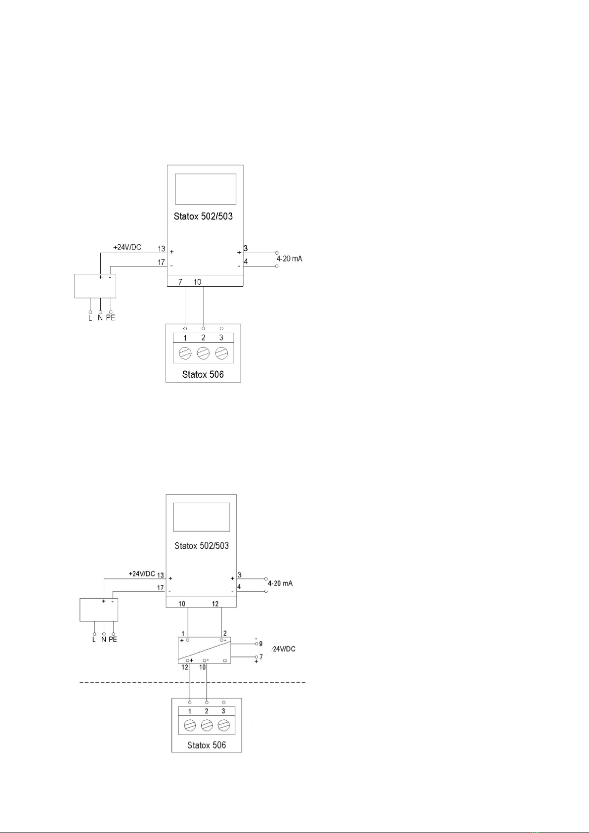
Power supply: 24 VDC (12 -28 VDC)
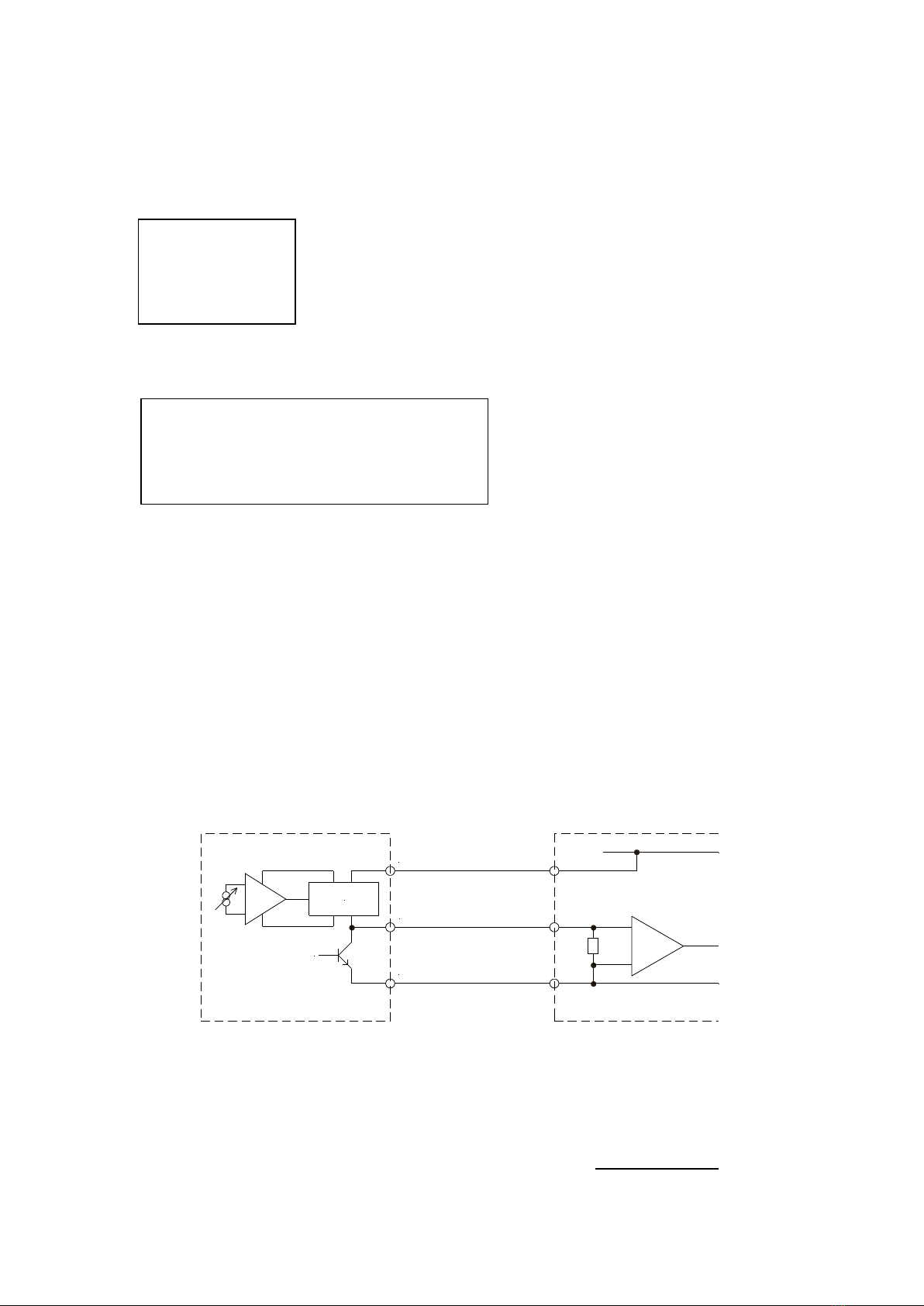
Connections: 2- or 3-wire operation
Terminal width: 0.25 –2.5 mm² (AWG 24 –12)
Output: 0 - 22 mA, max. load 545 Ohm
Service mode: 2 or 4 mA adjustable
System failure: 0 mA 3-wire operation, 2 mA 2-wire operation
Overrange: 22 mA
Display: 8-digits, 14 segments
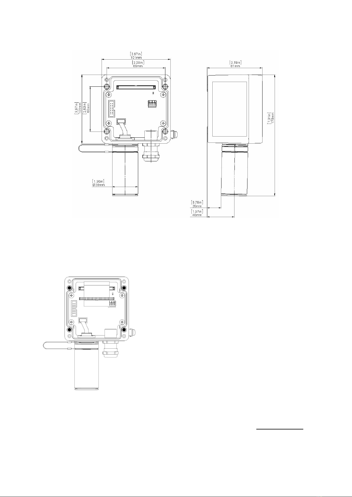
Dimensions (HxWxD): 180 x 111 x 81 mm
Weight: ca. 1200 g
Housing material: Cast aluminium, enameled / stainless steel
Ingress protection EN 60529: IP 66
Installation: Sensor downwards
EMV: EN 50270
ATEX marking: Ex ib IIB T4 Gb
Application: II 2G
Approval: BVS 18 ATEX E 066 X / N2
(X- Marking: requires potential equalization along the intrinsically safe loop)
Power supply Ui :max. 28 VDC
Current Ii : max. 93 mA
Power Pi: max. 650 mW
Internal capacity Ci : 24 nF
Internal Inductivity Li : neglectable
Functional safety: SIL 2 compliant with IEC 61508
Please find the sensor specifications in the detailed manual on our homepage www.compur.com !
Specifications are subject to change without notice, and are provided only for comparison of products. The conditions under which
our products are used, are beyond our control. Therefore, the user must fully test our products and / or information to determine
suitability for any intended use, application, condition or situation. All information is given without warranty or guarantee. Compur
Monitors disclaims any liability, negligence or otherwise, incurred in connection with the use of the products and information. Any
statement or recommendation not contained herein is unauthorized and shall not bind Compur Monitors. Nothing herein shall be
construed as a recommendation to use any product in conflict with patents covering any material or device or its use. No licence is
implied or in fact granted under the claims of any patent. Instruments are manufactured by Compur Monitors GmbH & Co. KG,
Munich. The General Conditions of Supply and Service of Compur Monitors GmbH & Co. KG, Munich, are applicable.
5376 000 997 07 00 / 02.21 516238
Compur Monitors GmbH & Co. KG
Weißenseestraße 101
D-81539 München
Tel.: ++49/89/ 6 20 38 268
Fax : ++49/89/ 6 20 38 184
http://www.compur.com
E-Mail: compur@compur.de
This manual suits for next models
1
Table of contents
Popular Transmitter manuals by other brands

Shinko
Shinko SGB instruction manual

Kramer
Kramer TA-110HD user manual

Cobalt Digital Inc
Cobalt Digital Inc BlueBox BBG-OE-MK2 Fiber-To-Coax quick start guide

Enersound
Enersound T-588 quick start guide

RKI Instruments
RKI Instruments 65-2646XL0504SS Operator's manual

Wave Central
Wave Central Axis Series User and Programming Guide