ComSonics Companion User manual

USER GUIDE
CSI Doc. 101453-001
CATV Digital / Analog
Signal Level Meter
with
Active and Passive
Ingress Testing
TM

Companion
i1 - 8 0 0 - 3 3 6 - 9 6 8 1
Limited Warranty (brief)
Hardware: ComSonics, Inc. (ComSonics) warrants to the original end user
(Customer) that the new ComSonics branded products will be free from defects
in workmanship and materials, under normal use, for one (1) year from the date
of original shipment. ComSonics warrants repaired and refurbished ComSonics
products for ninety (90) days from date of shipment.
Software: ComSonics warrants to the Customer that the Workstation Application
software will perform in substantial conformance to program specifications for a
period of ninety (90) days from the date of original shipment. ComSonics warrants
the media containing the software against failure during the warranty period.
ComSonics makes no warranty or representation that the operation of the soft-
ware products will be uninterrupted or error free, or that defects in the software
products will be corrected.
Software License (brief)
ComSonics grants you, the Customer, a limited nonexclusive license to use the
accompanying software program(s) (the Software) subject to the terms and re-
strictions set forth in this License Agreement. You are not permitted to use the
Software in any manner not expressly authorized by this License. You acknowl-
edge and agree that ownership of the Software and all subsequent copies thereof
regardless of the form or media are held by ComSonics or its suppliers.
Complete Limited Warranty and Software License Agreement documentation is
printed in the back section of this document.
Technical Support
ComSonics maintains a Technical Support Service for customer convenience.
Phone 1-800-336-9681 or 1-540-434-5965
Monday - Friday: 8:00 a.m. - 5:00 p.m. Eastern Time
Copyright
All material in this manual is the property of ComSonics, Inc. and protected under
the United States copyright law. No material shall be reproduced or used in any
form or by any means (graphic, electronic, or mechanical, including photocopying,
recording, taping, or information storage and retrieval systems) without the written
permission of:
ComSonics, Inc.
1350 Port Republic Road
Post Office Box 1106
Harrisonburg, Virginia 22801 USA
Phone: (540) 434-5965 USA Toll Free: (800) 336-9681
Fax: (540) 434-9847
Email: info@comsonics.com
Internet: www.comsonics.com
Companion is a trademark of ComSonics, Inc.
© 2007-2012 ComSonics, Inc. All Rights Reserved
Document 101453-001 Rev. L
Configuration Utility V3.3 Multiplan, FW 3.5, Modem FW 12
2012-09-05 sh

w w w . c o m s o n i c s . c o m ii
Table of Contents
Introduction
Features, Unpacking, Battery Care..............................................................1
General Operation
Power Management .....................................................................................2
Description of Operational Controls .............................................................2
Screens and Modes
Power On, Home..........................................................................................3
Favorite Channels ........................................................................................4
Single Channel, Analog................................................................................5
Single Channel, Digital.................................................................................6
Throughput...................................................................................................7
Reverse Path Analysis .................................................................................8
X-Ray Reverse Ingress ................................................................................9
Auto Test....................................................................................................10
Config(uration) Select ................................................................................12
Upload Test Data .......................................................................................13
Updates......................................................................................................13
Configuration Utility
Quick Guide ...............................................................................................14
Overview ....................................................................................................15
Customize Settings ....................................................................................16
Configuration Items..............................................................................17
Channel Setup Screens.......................................................................19
Auto Test Setup ...................................................................................20
Group Download..................................................................................22
Miscellaneous Detail............................................................................24
Download Firmware ...................................................................................26
Download Modem Firmware ......................................................................28
File System Integrity Check .......................................................................28
Select Port..................................................................................................29
Update Calibration File...............................................................................30
Warning Messages, Download ..................................................................32
Battery Replacement ......................................................................................33
RF Input Connector Replacement.................................................................33
Configuration Utility Installation
Windows XP Configuration Utility Installation ............................................34
Windows 7 Configuration Utility Installation ...............................................38
Test Companion to Computer Communications (XP and 7) ......................41
Test Server Setup ...........................................................................................43
Test Server Placement Recommendation .................................................45
Standard EIA Channel Table..........................................................................47
Specifications .................................................................................................48
Companion Package / Accessories ..............................................................49
Terminology Reference..................................................................................49
Limited Warranty ............................................................................................50
Software License Agreement ........................................................................52
Notes on Throughput Test Sequence...........................................................54

Companion
iii 1 - 8 0 0 - 3 3 6 - 9 6 8 1
Power ButtonConfiguration and Charging
Connector (Mini USB)

w w w . c o m s o n i c s . c o m 1
Introduction
The ComSonics Companion™ is an installer type CATV signal level meter
providing analog and digital measurement functions plus active and passive
ingress testing to uncover ingress problems the first time out. All this in a rugged
compact hand held package.
Features:
Affordable and highly functional
Digital and Analog measurements
Vivid color display
Cable modem
Scrolling touch pad user interface
A PC based Configuration Utility software kit is available to manage custom
configuration settings. The kit contains the PC workstation application and
a communications cable to personalize the Companion to system specific
parameters. The software kit is provided on an as requested basis with
Companion purchases or as a special order.
Unpacking
The Companion and its accessories are included in a shipping container designed
to provide the maximum protection during shipment. Immediately upon receipt,
inspect the container and contents for signs of physical damage. Notify the freight
forwarder of any damage detected.
Battery Care
An internal Lithium Ion (Li-Ion) rechargeable battery pack powers the Companion
meter. A mini USB charging connector is located, under a cover, on the right side
of the unit. An overnight charge is recommended to fully charge the battery. The
Companion must be powered off to charge the battery. Continuous operation of
the unit while connected to a charger is not possible as the battery will become
depleted. The Companion automatically powers off when the battery charge con-
dition is low to protect the battery from excessive discharge.
Use the included AC Adapter Charger, a PC USB cable (USB port must be
capable of supplying 500 mA), or the optional Vehicle Charger.
Note: When charging from a PC with a USB cable, charging may be interrupted
if the PC enters Sleep or Hibernate mode.
Caution
Failure to properly charge the battery may result in reduced battery life. Use of DC
inverters, other chargers, or AC adapters may cause equipment failure, create a
safety hazard, and void the warranty.
Refer to the ComSonics Battery Usage Guide publication for more information on
battery maintenance.
The guide can be found on the ComSonics website under Downloads:
http://www.comsonics.com/pdfs/BatteryUsage.pdf
Charge the battery fully before the first use!

Companion
21 - 8 0 0 - 3 3 6 - 9 6 8 1
General Operation
The Companion front panel is equipped with five
function buttons. Located below the function
buttons are several cursor controls; OK,
CANCEL, Left / Right arrows, and a touch rotary
control. The power On / Off button is located on
the upper right side of the case. The combina-
tion charging / configuration interface connector
is located, under a cover, below the power
button.
Power Management
To maximize runtime and conserve battery
power the unit employs a power management
scheduler. The scheduler refreshes after a
button press or user control action.
The scheduler performs the following actions:
2 minutes, the display back light dims.
4 minutes, the display back light goes off.
10 minutes, the unit turns off.
Description of Operational Controls
Power Button
Press to turn the unit on. There is a 3 second delay before the display lights.
Total start up time is approximately 15 seconds.
Press and hold for 2 seconds to turn the unit off.
Favorite Channels Button
Activate Favorite Channels Mode.
Single Channel Button
Activate Single Channel Mode.
Home Button
Return operation to the Main Menu
(HOME) screen. Display the
information screen.
Throughput Button
Activate Throughput Mode.
Auto Test
Activate Auto Test Mode.
Left / Right Arrow Buttons
Select (highlight) an on-screen
option. Step to next selection.
Touch Pad Rotary Control
Select items in the current option.
Scroll to next selections.
OK Button
Activate the selected item or option.
Cancel Button
Exit the current selection or option.
HomeFavorite
Channels
Single
Channel
Through
put
Auto Test

w w w . c o m s o n i c s . c o m 3
Power On, Home
On power up, the Companion enters the last active mode.
Press the Home button to display the HOME screen. Press the left / right arrow
button or use the touch rotary control to highlight a function. Press OK to activate
the selected function.
Select MORE to access the HOME(2) screen.
From the Home screen, press and hold the Home button to display the first
information screen.
Press the right arrow to display a second information screen.
A battery symbol, in the upper right corner, indicates the relative charge status
of the internal battery.
When a charger or PC cable is connected to an operating Companion, the battery
symbol color changes to white and the segments cycle from left to right.
Full Charge ≈75% Charge
Remaining
≈50% Charge
Remaining
less than 25%
Charge Remaining

Companion
41 - 8 0 0 - 3 3 6 - 9 6 8 1
Favorite Channels
The screen shows five Favorite Channels in
a vertical bar display combination. The Visual
carrier level is displayed for analog channels
and the digital multiplex power is displayed for
digital channels. Digital channels are displayed
with a graphic offset for ease of visual refer-
ence. Scaling of the display is performed
automatically. The slope is calculated based on
the maximum channel level minus the minimum
channel level, including the digital channel off-
set. A pass / fail indicator is displayed based on
the levels and slope limit guides. Failing com-
ponents are shown in red.
Note: The positioning and length of the limit
brackets are based on the current cursor
channel type. Typically the limit settings are
different between analog and digital channel
types.
The favorite channels, level limits, and maximum slope values can be changed
with the PC Configuration Utility.
Channel Selection
The number, frequency, and level of the currently selected channel are shown.
Press the left / right arrow button or use the touch rotary control to select another
channel of the five shown. The selected channel is indicated by an asterisk.
Press the OK button or the Single Channel mode button for a single channel
display of the selected Favorite Channel.

w w w . c o m s o n i c s . c o m 5
Single Channel, Analog
The screen shows a single channel in a vertical
bar display. Based on the active configuration
setting, the channel is displayed in the proper
analog format. Scaling of the display is per-
formed automatically. The analog V-A value is
calculated as the difference between the video
and the audio carrier levels. A pass / fail indica-
tor is displayed based on the levels and V-A
limit guides. Failed components are shown in
red.
The analog channel level and V-A limits can be
changed with the PC Configuration Utility.
Channel Selection
The channel number, type, and visual fre-
quency are shown. Press the left / right arrow
button or use the touch rotary control to select
another channel.
If the Favorite Channel button is pressed, the last selected Favorite Channel
remains selected unless the current single channel is a designated favorite
channel. If the current single channel is a designated favorite channel, it is then
the selected channel in the Favorite Channel mode.
Secondary Audio
Analog channels with secondary audio enabled display a double audio bar with
additional SA and V-SA level displays.
Secondary Audio is a discrete audio carrier in
addition to the standard audio carrier. It is used
mostly in European channel sets and is not the
same as SAP formerly used in NTSC analog
broadcast channels. SAP or second audio
program is multiplexed onto the 4.5 MHz audio
carrier as is the BTSC or MTS stereo
component.

Companion
61 - 8 0 0 - 3 3 6 - 9 6 8 1
Single Channel, Digital
The screen shows the selected channel in a
vertical bar display. Based on the active con-
figuration setting, the channel is displayed in
the proper digital format. Scaling of the display
is performed automatically. The flatness value
is based on a three point measurement.
BER values are based on calculations derived
from the FEC measurements or the correspond-
ing MER measurements. A pass / fail indicator
is displayed based on power, flatness, MER, pre
-FEC BER, and post-FEC BER limit guides.
Failed components are shown in red.
The digital channel power, flatness, MER, pre-
FEC BER, and post-FEC BER limits can be
changed with the PC Configuration Utility.
Channel Selection
The channel number, channel type, and center frequency are shown. Press the
left / right arrow button or use the touch rotary control to select another channel.
If the Favorite Channel button is pressed, the last selected Favorite Channel
remains selected unless the current single channel is a designated favorite
channel. If the current single channel is a designated favorite channel, it is then
the selected channel in the Favorite Channel mode.
Throughput
Configuration Notice
Applies to the Throughput mode on the next page.
The Companion must be provisioned in the system with the throughput server
address configured to complete the full Throughput test. If a non provisioned
server address is set, the downstream and upstream levels are displayed but the
test stops with a server error message. No pass / fail message is displayed.
Upstream and downstream power level meas-
urements can be made with the accompanying
pass / fail message if the server address box in
the Configuration Utility is left blank.
The downstream frequency and modulation
along with the upstream frequency and symbol
rate are displayed for informational purposes.
These values are not used for pass / fail
criteria.
Refer to page 18 for more information.

w w w . c o m s o n i c s . c o m 7
Throughput
The screen shows downstream and upstream
gauges, status indicators, and measurement
values.
A pass / fail indicator is displayed based on
downstream power, upstream power, upstream
throughput, and downstream throughput limit
guides.
The downstream frequency and modulation
along with the upstream frequency and symbol
rate are displayed for informational purposes.
These values are not used for pass / fail
criteria.
The downstream and upstream power limits,
upstream and downstream throughput limits,
downstream home frequency, and server
address can be changed with the PC
Configuration Utility.
The Downstream Frequency is selected based on the following:
The frequency set for the Downstream home frequency in the active
configuration*.
or
If ‘none’ was set as the Downstream home frequency in the active
configuration*, the unit initiates a scan for the downstream data channel;
with Companion firmware 3.3 or less, starting with the highest frequency
digital channel in the active configuration.
with Companion firmware 3.5 or greater, starting with the last selected
digital single channel. As it scans, the Down(stream) Freq(uency) shows the
frequency being scanned.
Status indicators show registration and subsequent data transfer activities during
the test.
R - Receive, downstream lock indicator
S - Send, upstream lock indicator
O - Online, online indicator
A - Activity, communications activity
Button Controls
Press the OK button to restart the throughput test.
or
Press another function button to exit the Throughput mode.
Note: The Companion must be provisioned in the system with the throughput
server address configured to complete the full Throughput test.
See page 54 for additional notes on the Throughput Test Sequence.
* By use of the Configuration Utility.

Companion
81 - 8 0 0 - 3 3 6 - 9 6 8 1
Reverse Path Analysis
View low frequency signals at a reverse path connection. Requires a temporary
interruption in subscriber service.
Selection Mode
Press the arrow buttons or use the touch rotary
control to select Frequency, Level, Display, or
Zoom. Press the OK button to enter the
selected mode.
Frequency Mode
Move the marker left or right using the arrow
buttons or the touch rotary control. Press the
OK button to toggle between the two highest
peaks. Press the Cancel button to return to the
Selection Mode.
Level Mode
Adjust the displayed level range using the arrow buttons or the touch rotary
control. Press the Cancel button to return to the Selection Mode.
Display Mode
Change the display mode to Normal, Average, or Peak hold using the arrow
buttons or the touch rotary control. Press the OK button to reset the Average or
Peak hold display. Press the Cancel button to return to the Selection Mode.
Zoom Mode
Adjust the displayed frequency range using the arrow buttons or the touch rotary
control. The zoom settings are x1, x2, x4, x10, or x20. Zoom settings are centered
around the marker position. Press the Cancel button to return to the Selection
Mode.
Note:
With Companion firmware 3.5 or greater, user adjustments made in the Reverse
Path Analysis display are retained, even when the unit is powered off, with the
exception of the Display Mode being reset to Normal when the unit is powered
on.
With Companion firmware 3.3 or less, user adjustments made in the Reverse
Path Analysis display are maintained until power off. At power on, the display is
restored to the factory default settings.
Note: If the Companion unit does not contain
factory installed Reverse Path hardware, a
screen appears stating the selected function
not available.

w w w . c o m s o n i c s . c o m 9
X-Ray Reverse Ingress
Used with the Qualifier X-Ray system. Requires a temporary interruption in
subscriber service. Connection required in the reverse path.
Notice
This function operates in conjunction with a
Qualifier X-Ray vehicle mounted device (option
101396-001C). Refer to the Qualifier X-Ray
User Guide for installation and operational
information. The Companion is used for
shielding integrity measurements.
A D2I* measurement is made when the X-Ray
Reverse Ingress function is activated. Press
the OK button to repeat the measurement.
Shielding Integrity Measurement
The Qualifier X-Ray System utilizes a unique
measurement method to determine the relative
shielding integrity of a customer premise without
a need to enter the structure. This method
provides the user with a graphic and numeric
display representing a calculated shielding
factor, in dB, of the premise under test.
The flexible coaxial cable normally used for drops and internal distribution typically
has a shielding integrity factor in the range of 80 to 120 dB. But with the addition
of connectors, splitters, DVRs, televisions, PC modems, and other devices along
with improper installation techniques, the total overall shielding integrity can
degrade appreciably. The possibility of noise ingress (undesirable signals in the
upstream path) increases greatly if the shielding integrity is not sufficient. Noise
ingress can cause interference with the return path signals and reduce the
reliability of two-way signal communications.
The Companion X-Ray system enables the user to measure shielding integrity
in the range of 100 dB (very good) to 20 dB (very poor). For easy status
determination, each measurement includes a PASS or FAIL indication, based
on the threshold value selected in the PC Configuration Utility.
Calculation theory for shielding integrity referenced to 75 feet:
D2I = Pmax [+85.74] - (antenna factor [2.5] + free space loss [28.39]) - measured value
*D2I is the acronym for Dwelling Ingress Integrity
Note: If the Companion unit does not contain
factory installed X-Ray Ingress hardware, a
screen appears stating the selected function
not available.

Companion
10 1 - 8 0 0 - 3 3 6 - 9 6 8 1
Auto Test - 1
The AUTO TEST function executes an auto
test routine associated with the active
configuration setting. Auto test routines must
be defined in the PC Configuration Utility and
are downloaded with the configuration setting.
Configuration settings are downloaded
individually or by the group download
procedure. Only one auto test routine can be
associated with a configuration setting.
Refer to page 20 for Auto Test Setup.
If the active configuration setting does not have
an associated auto test, the Companion
displays a No Test File for Selected Config
message .
Press the Auto Test function button or select
Auto Test on the HOME(2) screen to initiate the
auto test routine.
A test name must be first entered.
To enter a test ID name, use the rotary touch
control to select alphanumeric characters. A
clockwise rotation sequences in the order
AB...YZ01...89-. A counter clockwise rotation
sequences in the order -98...10ZY...BA. Both
rotation sequences use wrap around. Use the
right arrow to move to the next position. If
needed, use the left arrow to move back. The
test name can be one to ten characters.
Press OK to set the test name and show the
selections of Channel Tests and Reverse Path.
IMPORTANT: Connect the Companion to the
downstream path before starting Channel
Tests. Example: tap, house drop, or inside
customer premise.
Highlight the Channel Tests icon and press OK.
If test results already exist with the same ID
name, a confirmation window appears. Choose
No to keep the existing results or Yes to
overwrite the previous test results.
A progress bar shows and the current channel
under test is indicated.
The test completes with a PASS or FAIL
message. Refer to the next page for more on a
FAIL message.

w w w . c o m s o n i c s . c o m 11
Auto Test - 2
IMPORTANT: Connect the Companion to the
upstream path before starting Reverse Path.
Example: drop cable side of customer ground
block.
Highlight the Reverse Path icon and press OK.
If test results already exist with the same ID
name, a confirmation window appears. Choose
No to keep the existing results or Yes to
overwrite the previous test results.
A progress bar shows.
The test completes with a PASS or FAIL
message. See below for more on the FAIL
message.
A FAIL message is shown if a measurement in
the auto test does not meet the pass / fail
criteria of the active configuration setting . The
pass / fail limits are defined in the PC
Configuration Utility.
Press OK to display the failed items with a
description.
The Auto Test procedure can be repeated as
needed.
Since test results already exist with the current
ID name, a confirmation window appears.
Choose Yes to repeat the test and overwrite
the previous test results.
Note: Subsequent tests overwrite previous test
results unless the test ID name is changed.
Press the HOME button or another function button to exit the auto test mode.

Companion
12 1 - 8 0 0 - 3 3 6 - 9 6 8 1
Config(uration) Select
The CONFIG SELECT function allows for a
convenient method to quickly change the active
configuration setting in the Companion without
the need to be connected to a PC.
Use the PC Configuration Utility to create and
download several unique configuration settings
(channel plans) to the Companion. The active
configuration setting can be readily changed to
match the measurement or location criteria.
Press the right arrow to move down or the left
arrow to move up to select a configuration
setting. The touch rotary control can be used
also. The names are listed in alphabetical
order.
Press the OK button to activate the highlighted
configuration setting. The selected setting is
copied to the active status but remains in the
list for future use.
The selected setting is active immediately.
Companion power does not need to be cycled.
The name of the active configuration setting is
displayed on the HOME and HOME(2) screens.
Note: Configuration Settings listed in a Companion can only be deleted by using
the PC Configuration Utility.
Refer to page 16 for information on creating configuration settings.

w w w . c o m s o n i c s . c o m 13
Upload Test Data
The UPLOAD TEST DATA function is a
method to remotely transfer Auto Test data to
an FTP server. The FTP server IP is entered
on the Settings screen in the Configuration
Utility.
The Companion must be connected to the
downstream path and powered on.
Data files transferred to the server are named
by the alphanumeric characters entered on the
Companion prior to running an auto test.
Channel Test data files are identified by xxxxxxx.csv.
Channel Test error files are indentified by xxxxxxx.err.
Return Path Analysis (RPA) data files are identified by xxxxxxx.rpa.csv.
Return Path Analysis (RPA) error files are identified by xxxxxxx.rpa.err.
Error files (.err) are created only when a measurement is out of limits.
Important: The Upload Test Data function transfers all stored test data from the
Companion and then clears all test data from the Companion.
The Companion must be provisioned to operate on the network (cable system)
being tested and that a server/computer must be configured to receive and store
the sent data.
Updates
Allows the user to remotely download and install
firmware updates.
Button Controls
Select Updates from the HOME(2) screen.
Press the OK button to begin the update. The
Companion will automatically restart to
complete the installation of the new firmware.
Note: The Companion must be provisioned for
operation of the Firmware Update mode.
Firmware Update Sequence
‘Press OK to Search for Update’
‘Waiting for Modem Reset’ (if needed)
‘Waiting for Modem to Connect’ (if needed)
‘Waiting for Link’
‘Looking for Update’
If no update is available:
‘No Update Available’
If installed unit firmware version matches download firmware version:
‘Available firmware version is already installed. Press Cancel to exit.’
If update is available:
‘Receiving Update __%’ (percentage complete)
‘Unpacking Update’
‘Installing Update’
Unit reboots

Companion
14 1 - 8 0 0 - 3 3 6 - 9 6 8 1
Configuration Utility Quick Guide
Important: Install the Utility Software before connecting the Companion.
1. Install the Configuration Utility software.
First time only.
2. Start the Configuration Utility.
3. Open a configuration setting to customize.
3. Set selections on the Settings screen.
5. Set channel selections on all eight Channel screens.
6. Set selections on the Auto Test Setup screen, as desired.
7. Save Settings to PC and name the new configuration settings.
If the settings name contains spaces, the save function replaces the spaces
with underscores. Example: HOUSE DROP is saved as HOUSE_DROP.
8. Repeat the procedure for additional new configuration settings.
9. From the Settings screen, click Download Current Settings to Unit.
The current download is added to any previously downloaded configuration
settings in the Companion.
If the settings name contains spaces, the download function replaces the
spaces with underscores. Example: HOUSE DROP is downloaded as
HOUSE_DROP.
Use Groups for ease of downloading multiple settings in a single operation.
10. On the Group Download screen, Create a New Group.
11. Add Configuration Settings to Selected Group.
12. Repeat Add Settings for all desired configuration settings.
13. From the Group Download screen, click Download Group.
If a settings name contains spaces, the download function replaces the
spaces with underscores. Example: HOUSE DROP is downloaded as
HOUSE_DROP.
IMPORTANT
The Download Group function removes all stored configuration settings from the
Companion and installs only the configuration settings in the current group.

w w w . c o m s o n i c s . c o m 15
Configuration Utility Overview
Utility Version 3.3
The Companion is shipped configured to the settings indicated as factory default
value. Use the PC Configuration Utility Software to create custom configuration
settings. The utility kit consists of an installation disk and a USB cable. The
software requires a modern PC running MS Windows 2000, XP, Vista, or 7;
an available USB port; and a minimum display resolution of 1024 x 768.
Units of Measure in the following list is dBmV. If dBµV is selected in the utility,
equivalent values are shown.
Configurable Settings
Customize the factory templates and save the customized settings.
Favorite Channels mode
Select the 5 channels displayed; [Channels 2, 12, 78, 100, and 115]*
Set digital channel display bar offset; 0 to +15 dB [+6 dB]*
Pass / Fail Limits
Set limits for:
Favorite Channels Mode
max Slope; 1 to 15 dB [5 dB]*
Analog Single Channel Mode
Video carrier
max level; +30 dBmV to 1 dB above min [+10 dBmV]*
min level; -30 dBmV to 1 dB below max [0 dBmV]*
Delta V-A
max; 9 to 18 dB (must be at least 1 dB above min) [17 dB]*
min; 8 to 17 dB [10 dB]*
Delta V-SA (secondary audio)
max; 9 to 25 dB (must be at least 1 dB above min) [17 dB]*
min; 8 to 24 dB [10 dB]*
Digital Single Channel Mode
Power Level
max; +30 dBmV to 1 dB above min [+4 dBmV]*
min; -30 dBmV to 1 dB below max [-10 dBmV]*
In Band Flatness; 0.5 to 3.0 dB [1 dB]*
MER
64-QAM min; 24 to 40 dB [27 dB]*
256-QAM min; 28 to 40 dB [31 dB]*
pre-FEC BER; 10E-5 to 10E-9 [10e-9]*
post-FEC BER; 10E-5 to 10E-9 [10e-9]*
Throughput Mode
downstream max power; +30 dBmV to 1 dB above min [+4 dBmV]*
downstream min power; -30 dBmV to 1 dB below max [-10 dBmV]*
upstream max power; 55 dBmV to 1 dB above min [45 dBmV]*
upstream min power; 0 dBmV to 1 dB below max [35 dBmV]*
upstream min speed; 128 kbps to 8 Mbps [1.5 Mbps]*
downstream min speed; 128 kbps to 15 Mbps [3 Mbps]*
Global Settings
Analog Channels
Aural Offset; 0 to 10.0 MHz [4.5000 MHz]*
Secondary Audio Offset; 0 to 10.0 MHz [0.000 MHz]*
Digital Channels
64-QAM Bandwidth; 0 to 20.0 MHz [5.0570 MHz]*
256-QAM Bandwidth; 0 to 20.0 MHz [5.3610 MHz]*
QPSK Bandwidth; 0 to 20.0 MHz [0.7720 MHz]*
Throughput Mode
Downstream home frequency; enabled channels digital frequency [none]*
Reverse Path Analysis
Reverse Path Max Level; -40 to 60 dBmV [-40 dBmV]*
X-Ray
Threshold Pass / Fail Limit; 20 to 100 dB [50 dB]*
Frequency; 27.45, 27.47, or 27.49 MHz [27.47 MHz]*
Units of Measure
dBmV or dBµV [dBmV]*
Server Setup
Throughput server address; [blank]*
FTP Server IP; [blank]*
Note: See Throughput Server modes of operation.
* [StdEia default value]

Companion
16 1 - 8 0 0 - 3 3 6 - 9 6 8 1
Configuration Utility - Customize Settings
Utility Version 3.3
Run the Configuration Utility
Double-click on the Companion Multiplan Config desktop icon to start the utility.
or
From the All Programs list, move the pointer to ComSonics, Inc > Companion
Multiplan Config and left click.
The Settings screen initially displays the default configuration settings. After the
initial use, the last used configuration setting is automatically loaded on startup.
Additional configuration setting templates can be found by selecting Restore
Factory Defaults under the File menu.
Settings Screen: Button Items
The Refresh button, at the top center of the screen,
updates the Current Unit Config Settings list from a
connected Companion (Companion firmware 2.6 or
greater). The Companion must contain at least one
configuration setting to populate the list. A message
appears if the Companion has no configuration
settings.
The major function buttons are on the lower right of the screen.
They are used to Save and Open a configuration setting on the
computer, to Download a configuration setting to a Companion,
and to Retrieve Auto Test Results from a Companion.
Note: The retrieve function uploads all stored results data from
the Companion and then clears all results data from the
Companion. Refer to page 21 for more information.
Table of contents
Other ComSonics Measuring Instrument manuals

ComSonics
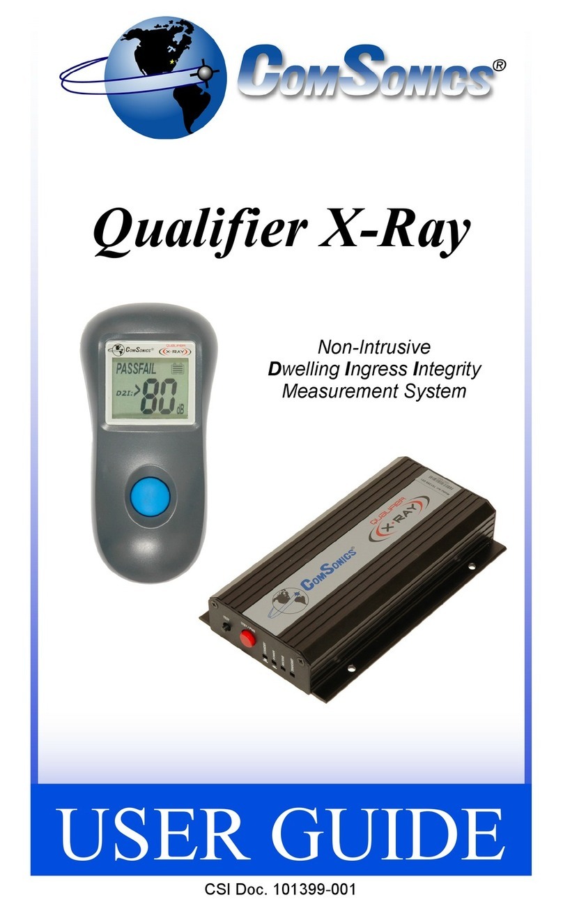
ComSonics Qualifier X-Ray User manual

ComSonics
ComSonics QAM Sniffer III User manual

ComSonics
ComSonics QAM Shadow User manual

ComSonics
ComSonics Sniffer Shadow User manual

ComSonics
ComSonics QAM Sniffer User manual

ComSonics
ComSonics CyberTek QUALIFIER User manual

ComSonics
ComSonics PON-3 User manual
Popular Measuring Instrument manuals by other brands

PCME
PCME STACK 990 user manual

Agilent Technologies
Agilent Technologies Agilent E6474A Configuration guide

Veeder-Root
Veeder-Root EMR3 XStream-PKG Setup and operation manual

Endress+Hauser
Endress+Hauser analytikjena Biometra TOne operating manual

FMC Technologies
FMC Technologies Smith Meter I-75 Service manual

IRVI
IRVI ABRIS M series manual