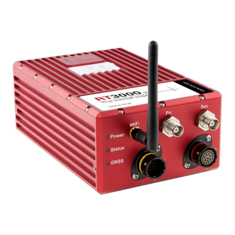
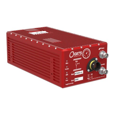
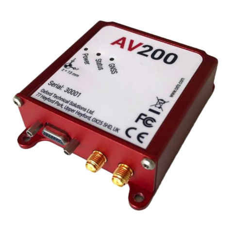
OXTS Survey+ v3 User manual

xF
User Manual
Covers Survey+ v3
models
The inertial experts.
Survey+
GNSS-aided
inertial
measurement
systems

2
Oxford Technical Solutions
Legal Notices
Information furnished is believed to be accurate and reliable. However, Oxford
Technical Solutions Limited assumes no responsibility for the consequences of use of
such information nor for any infringement of patents or other rights of third parties which
may result from its use. No licence is granted by implication or otherwise under any
patent or patent rights of Oxford Technical Solutions Limited. Specifications mentioned
in this publication are subject to change without notice and do not represent a
commitment on the part of Oxford Technical Solutions Limited. This publication
supersedes and replaces all information previously supplied. Oxford Technical Solutions
Limited products are not authorised for use as critical components in life support devices
or systems without express written approval of Oxford Technical Solutions Limited.
All brand names are trademarks of their respective holders.
The software is provided by the contributors “as is” and any express or implied
warranties, including, but not limited to, the implied warranties of merchantability and
fitness for a particular purpose are disclaimed. In no event shall the contributors be liable
for any direct, indirect, incidental, special, exemplary, or consequential damages
(including, but not limited to, procurement of substitute goods or services; loss of use,
data, or profits; or business interruption) however caused and on any theory of liability,
whether in contract, strict liability, or tort (including negligence or otherwise) arising in
any way out of the use of this software, even if advised of the possibility of such damage.
Copyright Notice
© Copyright 2019, Oxford Technical Solutions.
Revision
Document Revision: 190902 (See Revision History for detailed information).
Contact Details
Oxford Technical Solutions Limited
Park Farm Business Centre
Middleton Stoney
Oxfordshire
OX25 4AL
United Kingdom
Tel: +44 (0) 1869 814 253
Fax: +44 (0) 1869 251 764
Web: http://www.oxts.com
Email: [email protected]

RT-Range User Manual
Revision: 190902
3
Warranty
Oxford Technical Solutions Limited warrants its products to be free of defects in
materials and workmanship, subject to the conditions set forth below, for a period of one
year from the Date of Sale.
“Date of Sale” shall mean the date of the Oxford Technical Solutions Limited invoice
issued on delivery of the product. The responsibility of Oxford Technical Solutions
Limited in respect of this warranty is limited solely to product replacement or product
repair at an authorised location only. Determination of replacement or repair will be made
by Oxford Technical Solutions Limited personnel or by personnel expressly authorised
by Oxford Technical Solutions Limited for this purpose.
In no event will Oxford Technical Solutions Limited be liable for any indirect, incidental,
special or consequential damages whether through tort, contract or otherwise. This
warranty is expressly in lieu of all other warranties, expressed or implied, including
without limitation the implied warranties of merchantability or fitness for a particular
purpose. The foregoing states the entire liability of Oxford Technical Solutions Limited
with respect to the products herein.

4
Oxford Technical Solutions
Table of contents
Legal Notices__________________________________________________________________ 2
Copyright Notice _______________________________________________________________ 2
Revision ______________________________________________________________________ 2
Contact Details ________________________________________________________________ 2
Table of contents ______________________________________________________________ 4
Introduction __________________________________________________________________ 7
Easy operation ______________________________________________________________________ 8
Self-correcting ______________________________________________________________________ 8
Advanced processing_________________________________________________________________ 8
Related documents_____________________________________________________________ 9
Survey+ product family_________________________________________________________ 10
Survey+ (v3) _______________________________________________________________________ 10
Single antenna _____________________________________________________________________ 10
Dual antenna ______________________________________________________________________ 10
GLONASS_________________________________________________________________________ 11
BeiDou ___________________________________________________________________________ 11
200/250 Hz ________________________________________________________________________ 11
Satellite differential corrections ________________________________________________________ 11
Scope of delivery______________________________________________________________ 13
Survey+ system components __________________________________________________________ 13
Specification _________________________________________________________________ 14
Common specifications ______________________________________________________________ 16
Notes on specifications ______________________________________________________________ 16
Heading accuracy___________________________________________________________________ 16
Environmental protection _____________________________________________________________ 17
Export control classification number ____________________________________________________ 17
Conformance notices __________________________________________________________ 18
Regulator testing standards ___________________________________________________________ 18
Software installation __________________________________________________________ 19
Hardware installation__________________________________________________________ 21
Survey+ orientation and alignment ______________________________________________________ 21

RT-Range User Manual
Revision: 190902
5
Antenna placement and orientation _____________________________________________________ 21
Operation ___________________________________________________________________ 23
Front panel layout __________________________________________________________________ 23
Co-ordinate frame conventions_________________________________________________________ 26
Ethernet configuration _______________________________________________________________ 33
Wi-Fi configuration__________________________________________________________________ 37
Dual antenna systems _______________________________________________________________ 40
Inputs and outputs ____________________________________________________________ 43
Digital inputs and outputs_____________________________________________________________ 44
Configuring the Survey+ ________________________________________________________ 47
Overview _________________________________________________________________________ 47
Working through NAVconfig___________________________________________________________ 48
NAVconfig Home section in NAVconfig __________________________________________________ 48
Start/Read Configuration section in NAVconfig ____________________________________________ 49
Read Configuration section ___________________________________________________________ 50
Hardware Setup section in NAVconfig ___________________________________________________ 51
IMU orientation tab __________________________________________________________________ 51
Primary antenna tab _________________________________________________________________ 53
Secondary Antenna tab ______________________________________________________________ 55
GNSS Differential Corrections tab_______________________________________________________ 60
Interfaces section in NAVconfig ________________________________________________________ 63
Advanced Tools section ______________________________________________________________ 71
The Write Configuration section of NAVconfig _____________________________________________ 79
Setting up the base station _____________________________________________________ 80
Using the RT-Base S_________________________________________________________________ 80
Initialisation process___________________________________________________________ 81
Real-time outputs ___________________________________________________________________ 81
Warm-up period ____________________________________________________________________ 82
Improving the configuration after a warm-up ______________________________________ 85
Committing the configuration to the Survey+ ______________________________________________ 85
Post-processing data __________________________________________________________ 90
Laboratory testing ____________________________________________________________ 91
Accelerometer test procedure__________________________________________________________ 91
Gyro test procedure _________________________________________________________________ 91

6
Oxford Technical Solutions
Testing the internal GNSS and other circuitry______________________________________________ 93
Using the orientation measurements _____________________________________________ 94
Operating principles ___________________________________________________________ 95
Internal components_________________________________________________________________ 95
Strapdown navigator ________________________________________________________________ 95
Kalman filter_______________________________________________________________________ 97
Revision history_______________________________________________________________ 98
Drawing list__________________________________________________________________ 99

RT-Range User Manual
Revision: 190902
7
Introduction
The Survey+ inertial navigation system (INS) device is an instrument for making
precision measurements of motion in real time.
From September 2019 the Survey+ became v3 with new functionality. v2 devices are
now end of life and include: Survey+ v2 and Survey+L1 v2.
To obtain high-precision measurements, the Survey+ uses mathematical algorithms
developed for use in fighter aircraft navigation systems. An inertial sensor block with
three accelerometers and three gyros (angular rate sensors) is used to compute all the
outputs. A WGS 84 modelled strapdown navigator algorithm compensates for earth
curvature, rotation and Coriolis accelerations, while measurements from high-grade
kinematic GNSS receivers update the position and velocity navigated by the inertial
sensors. This innovative approach gives the Survey+ several distinct advantages over
systems that only use GNSS:
•The Survey+ has a high (100 Hz 200 Hz or 250 Hz) update rate and a wide
bandwidth.
•The outputs are available with low, 3.5 ms latency.
•All outputs remain available continuously during GNSS blackouts when, for
example, the vehicle drives under a bridge.
•The Survey+ recognises jumps in GNSS position and ignores them.
•The position and velocity measurements the GNSS makes are smoothed to reduce
the high-frequency noise.
•The Survey+ makes many measurements GNSS cannot, for example acceleration,
angular rate, heading, pitch and roll.
A Survey+ system processes data in real time. The real-time results are output via an
RS232 serial port, or over 10/100 Base-T Ethernet using a UDP broadcast. Outputs are
time-stamped and refer to GPS time; a 1PPS timing sync can be used to give accurate
timing synchronisation between systems. The inertial measurements are synchronised
to the GPS clock.

8
Oxford Technical Solutions
Internal data logging enables the data to be reprocessed post-mission. Data can be
collected in the unit, downloaded using “ftp” protocol, processed on a PC and viewed
using the NAVsolve.
Easy operation
There is minimal configuration required to use the system. The configuration can be
saved to the Survey+ so it can operate autonomously without user intervention. A lot of
work has been put into the initialisation of the inertial algorithms so the Survey+ can
reliably start to navigate in the vast majority of situations.
The single unit contains inertial sensors, GNSS receiver, data storage and CPU. One or
two antennas need to be mounted outside the vehicle where they have a clear view of
the sky. A 10–50 V dc power supply can be obtained from most vehicles. A laptop
computer allows real-time viewing of the results.
Self-correcting
Unlike conventional inertial navigation systems, the Survey+ uses GNSS to correct all
its measurements. GNSS makes measurements of position, velocity and (for dual
antenna systems) heading. Using these measurements, the Survey+ is able to keep other
measurements, such as roll and pitch, accurate. Tight coupling of the GNSS and inertial
measurements means the raw GNSS data can also be used. There is no drift from the
Survey+ in any of the measurements while GNSS is present.
Advanced processing
In poor GNSS environments, drift times can be halved by using the combined results of
processing forwards and backwards in time. Our proprietary gx/ix™ processing engine
can further improve performance with single satellite aiding algorithms and tight
coupling of the inertial and GNSS measurements, meaning position updates even with
fewer than four satellites in view.

RT-Range User Manual
Revision: 190902
9
Related documents
This manual covers the installation and operation of Survey+ systems, but it is beyond its
scope to provide details on service or repair. Contact OxTS support or your local
representative for customer service-related inquiries.
Additional manuals provide further information on some of the software and
communication types mentioned in this manual. Table 1 lists related manuals and where
to find them.
Table 1. Supplementary manuals
Manual
Description
NAVdisplay
Manual
For viewing real-time information from an RT.
https://support.oxts.com/hc/en-us/articles/115002433285-NAVdisplay-Online-
manual
NAVgraph
Manual
For plotting and exporting captured data.
https://support.oxts.com/hc/en-us/articles/115002433465-NAVgraph-Online-manual
NCOM
Manual
For decoding and using the NCOM format.
www.oxts.com/Downloads/Support/NCOM Manual and Code
Drivers/ncomman.pdf
NCOM C
Code Drivers
A collection of C functions that can be used to decode the binary protocols from the
RT.
www.oxts.com/Downloads/Support/NCOM Manual and Code Drivers/ncomrx.zip
NMEA 0183
Description
NMEA description manual for the NMEA outputs.
www.oxts.com/Downloads/Support/NMEA/nmeaman.pdf
NAVsolve
Manual
Explains how to use our post-processing application.
https://support.oxts.com/hc/en-us/articles/360000225449-NAVsolve-manual

10
Oxford Technical Solutions
Survey+ product family
Survey+ (v3)
Survey-grade GNSS receivers provide high-precision position and velocity
measurements even in high multipath environments. GPS & GLONASS enabled as
standard on primary and secondary receivers. Can be BeiDou enabled. The Survey+
with RTK support is dual antenna. 100 Hz is the standard output rate. 200 Hz and 250
Hz options are available.
The options contained within each device type are listed in the “Specification” section
on page 15.
Single antenna
An advanced algorithm in the Survey+ software means most road vehicle users are able
to use a single antenna system. The Heading lock and Advanced slip features allow
Survey+ devices to maintain an accurate heading while completely stationary and while
driving with low vehicle dynamics.
Single antenna systems can experience reduced heading accuracy on aircraft, boats or
in low-speed land vehicles.
Dual antenna
Dual antenna systems provide high accuracy heading information and almost constant
heading performance under all conditions.
For aircraft or marine applications, or road vehicle applications on low-friction surfaces
(e.g. ice), a dual antenna system is recommended to maintain high accuracy heading.
Advanced processing in the Survey+ allows relock to occur after five seconds of a sky-
obstruction – unlike GNSS-only systems which can take several minutes; in this time
the Survey+’s heading will not have significantly degraded. The fast relock time is made
possible because the Survey+’s own heading is used to resolve the ambiguities in the
GNSS measurements. Resolution of these ambiguities is what normally takes several
minutes.

RT-Range User Manual
Revision: 190902
11
The heading software in the Survey+ enables significantly better performance and
coverage compared to GNSS-only solutions.
GLONASS
GLONASS capability adds the ability to utilise the Russian satellite constellation
GLONASS as well as the American constellation GPS. This means an extra 24 satellites
are available for the Survey+ to lock on to and obtain position and velocity updates
from.
In open sky conditions, the addition of GLONASS capability is of little benefit as the
GPS signals are unlikely to be interrupted and full accuracy can be achieved almost
100% of the time. However, in open-road testing situations there are likely to be bridges,
trees, and tall buildings that can block the view of satellites or cause multipath effect
errors. In these situations, GPS and GLONASS receivers are able to maintain 1 cm
accurate RTK positioning mode at times when GPS-only receivers are not. They are
also able to re-establish RTK lock and resolve its ambiguities after an obstruction faster.
BeiDou
BeiDou capability adds the ability to utilise the Chinese satellite constellation BeiDou
as well as the American constellation GPS and Russian constellation GLONASS. This
means an extra 34 satellites are available for the Survey+ to lock on to and obtain
position and velocity updates from. BeiDou is not compatible with the gx/ix™ tight
coupling algorithms.
200/250 Hz
1.
All Survey+ have the option of coming with a 200/250 Hz output of the inertial
measurement unit (IMU). The IMUs used in 100 Hz 200 Hz and 250 Hz products are
essentially the same, both with a fundamental sampling frequency of 1000 Hz. The
difference is the 3D filter used to integrate the accelerations and angular rates has a
smaller time step in the 250 Hz models, allowing a higher update rate.
2.
However, because of the smaller time step, measurements that depend on angular
acceleration are typically noisier on the 200/250 Hz products. The noise can be managed
by filtering the data to limit the bandwidth.
Satellite differential corrections
To improve the positioning accuracy of standard GNSS, two satellite-based differential
correction services are available. These are SBAS and TerraStar.
Services such as WAAS and EGNOS, are wide-area differential corrections provided for
free. They can provide an accuracy of better than 1 m CEP. WAAS is available in North
America; EGNOS is available in Europe; MSAS is available in Japan; GAGAN

12
Oxford Technical Solutions
is available in India; SDCM is available in Russia. Other parts of the world are not
covered and cannot use this service.
TerraStar is a subscription service. Survey+ systems that have TerraStar capability
include the necessary hardware to receive corrections. It is necessary to pay a licence
fee to activate these corrections. Capable Survey+ systems will use the TERRASTAR-
D service which can provide better than 10 cm position accuracy. TerraStar is available
on all continents. Marine versions also exist.
For more information, see TerraStar’s website: http://www.terrastar.net.

RT-Range User Manual
Revision: 190902
13
Scope of delivery
Survey+ products are supplied complete with, software, standard cables, a tape measure,
and a quick start guide. The user will have specified at the point of ordering which user
cable and antennas (including antenna cables) they need for their application.
Survey+ system components
Table 2 lists all items that are delivered with each standard Survey+ model.
Table 2. Summary of Survey+ system components
Description
RT500 and RT3000
Survey+unit
Power cable 77C0002B
User cable
Specify at point of ordering
Aux user cable
Specify at point of ordering
GNSS antennas
Specify at point of ordering
Ethernet cable (cross-over)
USB stick with manual and software
Tape measure
Quick start guide
The Survey+ product is RTK capable and requires the correct differential corrections
in order to work to full specification. Differential corrections can be supplied by an RT-
Base, GPS-Base, NTRIP or other suitable differential correction source.
In addition to the components supplied, the user will require a laptop computer or
other logging system

14
Oxford Technical Solutions
Specification
Specifications for Survey+ products can be found in Table 3 and Table 4. These
specifications are listed for operation of the system under the following conditions:
•After a warm-up period of 15 minutes’ continuous operation.
•Open-sky environment, free from cover by trees, bridges, buildings or other
obstructions. The vehicle must have remained in open sky for at least five minutes for
full accuracy.
•The vehicle must exhibit some motion behaviour. Acceleration of the unit in different
directions is required so the Kalman filter can estimate any errors in the sensors.
Without this estimation, some of the specifications degrade.
•The distance from the Survey+ measurement point to the primary GNSS antenna must
be known by the system to a precision of five millimetres or better. The vibration of
the system relative to the vehicle cannot allow this to change by more than five
millimetres. The system will estimate this value itself in dynamic conditions.
•For dual antenna systems, the system must know the relative orientation of the two
antennas to 0.05° or better. The system will estimate this value itself under dynamic
conditions.
•For single antenna systems, the heading accuracy is only achieved under dynamic
conditions. Under benign conditions, such as motorway driving, the performance will
degrade. The performance is undefined when stationary for prolonged periods of time.
Optionally, extended measurement ranges covering 30 g acceleration and 300°/s
angular rate may be requested. The specification using the extended measurement
range sensors can be marginally worse than those listed here.

RT-Range User Manual
Revision: 190902
15
Table 3. Survey+ specifications
Parameter
Survey+ v3
(Dual Antenna)
Positioning
GPS L1, L2 GLONASS
L1, L2
BeiDou L1, L21
Position accuracy2
1.5 m CEP SPS
0.6 m CEP SBAS
0.4 m CEP DGPS
0.1 m CEP PPP
0.2 m 1 L1
0.01 m 1 L1/L2
Velocity accuracy
0.1 km/h RMS
Roll/pitch
0.03° 1
Heading
0.1° 1
Acceleration
– Bias stability
5 μg 1σ
– Linearity
0.01%
– Scale factor
0.1% 1
– Range
100 m/s2
Angular rate
– Bias
0.01°/s 1
– Scale factor
0.1% 1
– Range
100°/s
Lateral velocity
0.2% 1
Update rate
100 Hz / 250 Hz
Input voltage4
10–48 V dc
Power
14 W
consumption
Dimensions
184 × 120 × 71 mm
Mass
1.5 kg
1Optional upgrade.
2To achieve specification, relevant differential corrections from a base station, NTRIP or
TerraStar subscription are required. The RTK accuracies are based on v2 products.
3With two-meter antenna separation. Wider separation will improve accuracy (supports up to
five-meter separation).
4Voltage range of connected devices such as radio modems must be considered.

16
Oxford Technical Solutions
Common specifications
Table 4. Survey+ common specifications
Parameter
Specification
Calculation
latency
3.5 ms
Operating
temperature1
-10° to 50 °C
Vibration
0.1 g2/Hz 5–500 Hz
Shock survival
100 g, 11 ms
Internal storage
32 GB
1 The operating temperature range for the antenna is much wider since it can be mounted outside the vehicle.
See specification below.
Notes on specifications
To achieve full accuracy in real time, the Survey+ products will require appropriate
differential corrections where applicable, either from a base station or with a TerraStar
licence. Alternatively, a RINEX file can be downloaded post-mission and used to post-
process the data to full accuracy.
For the TerraStar service, at least 30 minutes of open-sky condition may be required
before full accuracy is achieved. This service can easily achieve this accuracy in airborne
applications.
The “1” specification has been used for parameters where offset cannot be measured by
the Survey+, for example position (the offset of the base station cannot be found by the
Survey+ alone). The “RMS” specification was used where the offset is known, for
example velocity. For angles and measurements derived from the angles, the “1”
specification is used because the mounting of the Survey+ compared to the vehicle gives
an offset the Survey+ cannot measure.
The accuracy of the product will depend on the operating mode of the GNSS.
Heading accuracy
The heading accuracy that can be achieved by the dual antenna system in the Survey+’s
in Table 3 is 0.2° 1σ per metre of separation in ideal, open sky conditions. The system
can provide these accuracies in static and dynamic conditions. A four-metre separation is
required to reach the accuracy listed in Table 3. The maximum recommended separation
is five metres, at which it may be possible to achieve better accuracy than that listed if the
structure is rigid, including temperature variation.

RT-Range User Manual
Revision: 190902
17
For single antenna systems, the heading is calculated from the inertial measurements. The
accuracies listed in Table 3 are achievable under dynamic conditions. Under static
conditions the heading accuracy of single antenna systems will degrade.
Non-ideal mounting of the GNSS antennas will reduce the heading accuracy, particularly
for dual antenna systems.
Environmental protection
The Survey+ products are rated to IP65. To achieve IP65 it is necessary to have
connectors fitted to both TNC antenna connectors and to use self-amalgamating tape over
the TNC connectors.
Export control classification number
Export control regulations change, and so the classification number of the Survey+ may
also change. The information presented here was correct when the manual was published.
Survey+ products can fall under two different export control categories depending on the
type of accelerometer fitted internally. The type of accelerometer does not affect the
specification of the product, only the export control classification number (ECCN). Table
5 lists the ECCN for the products.
Table 5. ECCN for Survey+ products
Product
ECCN
Survey+
10G
7A103a1
Survey+
30G
7A003d

18
Oxford Technical Solutions
Conformance notices
The Survey+ complies with the radiated emission limits for 47 CFR 15.109:2010 class
A of Part 15 subpart B of the FCC rules, and with the emission and immunity limits for
class A of EN 55022. These limits are designed to provide reasonable protection against
harmful interference in business, commercial and industrial uses. This equipment
generates, uses and can radiate radio frequency energy and, if not installed and used in
accordance with the instructions, may cause harmful interference to radio
communications. However, there is no guarantee that interference will not occur in a
particular installation. If this equipment does cause harmful interference to radio or
television reception, which can be determined by turning the equipment off and on, the
user is encouraged to try to correct the interference by one or more of the following:
oRe-orient or relocate the receiving antenna.
oIncrease the separation between the equipment and the receiver.
The Survey+ incorporates a GNSS receiver. No GNSS receiver will be able to track
satellites in the presence of strong RF radiations within 70 MHz of either the L1 GPS
frequency (1575 MHz) or L2 1228 MHz.
The Survey+ conforms to the requirements for CE.
Regulator testing standards
Survey+ products
o47 CFR 15.109:2010 class A (radiated emissions).
oEN 61000-4 criterion A according to standard EN 301 489-1:2008 (-2:2009 electrostatic
discharge), (-3:2006+A2:2010 radiated immunity), (-4:2012 electrical fast transients),
(-5:2006 voltage surge) and (-6:2009 conducted radio frequency immunity).
oEN 55022:2010 class A according to standard EN 301 489-1:2008 (Radiated
electromagnetic emissions) and (conducted emissions).
oEN 55011:2009+A1:2010 class A according to standard EN 301 489- 1:2008 (Radiated
electromagnetic emissions).

RT-Range User Manual
Revision: 190902
19
Software installation
Included with every Survey+ is a USB stick containing the software package
NAVsuite. This package contains several programs required to take full advantage
of the Survey+’s capabilities. Table 6 lists the contents of NAVsuite.
Table 6. NAVsuite components
Icon
Software
Description
NAVdisplay
Used to view real-time data from OxTS products via
Ethernet or a serial port. It can also be used to transmit
special commands and replay logged data.
NAVstart
A menu from which you can navigate between OxTS
applications. This opens automatically when you are
connected to a unit.
NAVconfig
Used to create, send, and receive configurations from
OxTS products. As configurations vary between products
there is no manual for NAVconfig.
NAVsolve
Used to download raw data files from the Survey+ and
post- process the data. The configuration can be changed
and differential corrections can be applied before the
data is reprocessed. It can export NCOM, XCOM and
CSV file formats.
NAVgraph
Used to graph NCOM, XCOM and RCOM files created in
post-process. It can display graphs, cursor tables and map
plots and data can be exported in CSV or KML (Google
Earth) format.
NAVbase
Used to configure and manage RT-Base S and GPS-Base
base stations, which can be used to achieve RTK integer
level position accuracy.
Manuals
This folder contains PDF versions of relevant OxTS
manuals. Other manuals can be downloaded from the
OxTS website.
To install NAVsuite, insert the USB stick and run NAVsetup.exe. Follow the onscreen
instructions to install the software. By default, the installer creates the program files in
C:\Program Files (x86)\OxTS on 64 bit operating systems or C:\Program Files\OxTS on
32 bit operating systems.
The first time some OxTS applications are run, a firewall warning message similar to that
shown in Figure 1 may be triggered. This is because the program is attempting to listen for,
and communicate with, OxTS devices on the network. The firewall must be configured to
allow each program to talk on the network, or programs will not work as intended.

20
Oxford Technical Solutions
Figure 1. Windows Firewall warning message
Ensure both Private and Public networks are selected to ensure the software can continue functioning
when moving from one type to another.
Table of contents
Other OXTS Measuring Instrument manuals