Comtrol DeviceMaster ATS-XPE Operator's manual

Installation and Configuration Guide

Trademark Notices
Comtrol and DeviceMaster are trademarks of Comtrol Corporation. RocketPort is a registered trademark of
Comtrol Corporation.
Windows registered trademark of Microsoft Corporation.
Other product names mentioned herein may be trademarks and/or registered trademarks of their respective
owners.
URL References
All URLs in this document worked at the time of publication. Due to the nature of web sites, some links may
not work, and you may need to search their site to locate the referenced information.
First Edition, January 22, 2004
Copyright © 2003. Comtrol Corporation.
All Rights Reserved.
Comtrol Corporation makes no representations or warranties with regard to the contents of this document or
to the suitability of the Comtrol product for any particular purpose. Specifications subject to change without
notice. Some software or features may not be available at the time of publication. Contact your reseller for
current product information.
Document Number: 2000329

Table of Contents 3
Table of Contents
Installation and Setup ........................................................................................................................ 5
Audience .......................................................................................................................................................... 5
Product Overview ......................................................................................................................................... 5
Initial Hardware Installation ..................................................................................................................... 6
Powering on the ATS-XPE........................................................................................................................... 7
Other Installation and Configuration Procedures .......................................................................................................8
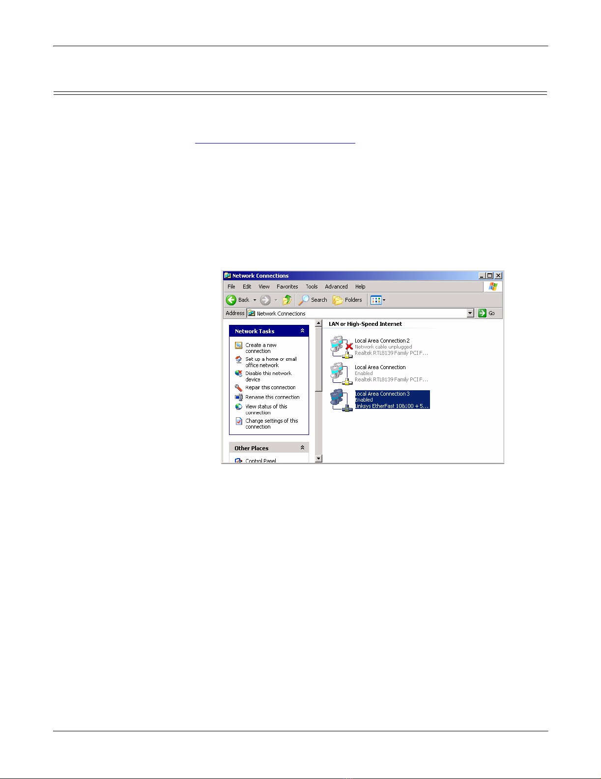
Configuring the Network Settings on the ATS-XPE ............................................................................. 9
Changing the Default Computer and Workgroup Names.................................................................. 11
Starting Routing and Remote Access Services .................................................................................... 13
Setting Up Dial-In........................................................................................................................................ 15
Setting Up Remote Desktop Access......................................................................................................... 19
Managing Files on the ATS-XPE .................................................................................................... 21
Accessing the ATS-XPE Using Remote Desktop................................................................................... 21
Using Remote Desktop through the Network ............................................................................................................21
Using Remote Desktop through a Modem..................................................................................................................23
PC104 RocketPort Option................................................................................................................ 25
Default PC104 Port Configuration .......................................................................................................... 25
Configuring the RocketPort Serial Ports .............................................................................................. 26
RocketPort Serial Port Connectors ........................................................................................................ 30
DB9 Connectors ...........................................................................................................................................................30
Building Additional DB9 Loopback Plugs ..................................................................................................................30
DB25 Connectors .........................................................................................................................................................30
Building Additional DB25 Loopback Plugs ................................................................................................................31
RJ45 Connectors ..........................................................................................................................................................31
Building Additional RJ45 Loopback Plugs.................................................................................................................31
Building an RS-485 Test Cable ...................................................................................................................................31
Building Null-Modem Cables ......................................................................................................................................32
Building Straight-Through Cables .............................................................................................................................32
Troubleshooting Serial Ports ................................................................................................................... 33
Using Test Terminal....................................................................................................................................................33
Testing a Comtrol Port....................................................................................................................... 34
Testing an RS-485 Port...................................................................................................................... 34
Test Terminal Modem Control Signals .............................................................................................34
Using Port Monitor ......................................................................................................................................................35
Starting Port Monitor ........................................................................................................................ 35
Changing Screen Appearance ............................................................................................................ 36
Column Setup ..................................................................................................................................... 36
Report Configuration ......................................................................................................................... 37
Port Monitor Files .............................................................................................................................. 37
Port Monitor Variables ...................................................................................................................... 38
Using Peer Tracer ........................................................................................................................................................40
Starting Peer....................................................................................................................................... 40
Log Functions ..................................................................................................................................... 41
Using Peer........................................................................................................................................... 41
Other Peer Commands ....................................................................................................................... 41
Device Driver and OS Capabilities and Limitations........................................................................... 41
Certified PCMCIA Adapters............................................................................................................ 43
Comtrol Certified PCMCIA Devices........................................................................................................ 43
Linksys Wireless PC Card (WPC11) ........................................................................................................ 43
Linksys EtherFast 10/100 + 56K Modem PC Card (PCMLM56)......................................................... 47
Installing Serial Devices .................................................................................................................. 49
Overview........................................................................................................................................................ 49
Installing Modems ....................................................................................................................................... 49

4 Table of Contents
Table of Contents
Troubleshooting and Technical Support ..................................................................................... 53
Troubleshooting Checklist ........................................................................................................................ 53
Enabling the Event Viewer ....................................................................................................................... 54
Using the Recovery CD .............................................................................................................................. 55
Customer Support Policy .......................................................................................................................... 56
Technical Support....................................................................................................................................... 57
Repair and Return Policy.......................................................................................................................... 57
Appendix A. Connectors................................................................................................................... 59
VGA Connector............................................................................................................................................. 59
PS/2 Keyboard and Mouse Connectors................................................................................................... 59
Ethernet Connectors .................................................................................................................................. 59
USB Interfaces ............................................................................................................................................. 60
Compact Flash Disk Connector ............................................................................................................... 60
AUX A and CONSOLE Port Connectors ................................................................................................. 61
PARALLEL Port........................................................................................................................................... 61
Serial Ports 1-8 Connector (Optional) .................................................................................................... 62
Appendix B. Specifications and Notices ...................................................................................... 63
Product Specifications............................................................................................................................... 63
Electromagnetic Compliances .....................................................................................................................................63
Environmental Condition Specifications ....................................................................................................................64
............................................................................................................................................. Hardware Specifications64
Technical Specifications ..............................................................................................................................................65
Default Operating System Configuration.............................................................................................. 66
Notices............................................................................................................................................................ 75
Radio Frequency Interference (RFI) (FCC 15.105) ....................................................................................................75
Labeling Requirements (FCC 15.19)...........................................................................................................................75
Modifications (FCC 15.21)...........................................................................................................................................75
Serial Cables (FCC 15.27) ...........................................................................................................................................75
Underwriters Laboratory ............................................................................................................................................75
Important Safety Information.....................................................................................................................................75
Appendix C. Default System Values .............................................................................................. 77
Accessing the Motherboard ...................................................................................................................... 77
Clearing the CMOS Setup.......................................................................................................................... 79
Applying Power to the AUX A Port ......................................................................................................... 79
Changing the Watch-Dog Timer............................................................................................................... 79
System I/O Address Map ............................................................................................................................ 81
First MB Memory Map................................................................................................................................ 82
Appendix D. Changing BIOS Configuration ............................................................................... 83
Getting Started ............................................................................................................................................ 83
Standard CMOS Setup ............................................................................................................................... 84
BIOS Features Setup .................................................................................................................................. 84
Chipset Features Setup.............................................................................................................................. 85
Power Management Setup ........................................................................................................................ 85
PNP/PCI Configuration.............................................................................................................................. 86
Load BIOS Defaults..................................................................................................................................... 87
Load Setup Defaults.................................................................................................................................... 87
Integrated Peripherals............................................................................................................................... 88
Supervisor Password and User Password............................................................................................. 88
SVGA Setup Introduction.......................................................................................................................... 89
Appendix E. Changing the WatchDog Timer .............................................................................. 91
Index ..................................................................................................................................................... 93

Installation and Setup 5
Installation and Setup
This section discusses the following topics:
• Audience
• Product overview
• Installing the hardware
• Configuring the network settings on the ATS-XPE
• Changing the default computer and workgroup names, for multiple unit
installations
• Starting the Routing and Remote Access service for remote access and for use
with Remote Desktop
• Configuring dial-in on the ATS-XPE
Note: Appropriate user accounts and permissions must be set up for dial-in
and Remote Desktop to work on the ATS-XPE.
Please refer to the End-User License Agreement for Microsoft®Windows®XP
Embedded shipped with the ATS-XPE for licensing information.
Audience
The DeviceMaster ATS-XPE requires that you have a working knowledge and
familiarity with the Windows XP operating system including areas such as:
• System administration
• Network configuration
• Operating system installation
Product Overview
The DeviceMaster ATS-XPE is a standalone, user-programmable microcomputer
designed to run Microsoft®Windows®applications in a solid-state environment.
The ATS-XPE model provides built-in Ethernet connectivity and is designed for
remote deployment and management of local programs and the attached serial
devices.
The ATS-XPE is designed as a deployment platform, not a development platform.
The solid-state compact flash technology does not support an unlimited number of
writes. While development could be done on the ATS-XPE, it is recommended that
application development is conducted on a different machine and the resulting
SERIAL PORTS 1-8 connector and fanout cable, if RocketPort PC104 option ordered.

6Installation and Setup
Initial Hardware Installation
application moved to, tested, and run on the ATS-XPE.
The ATS-XPE is running Comtrol Corporation’s customized version of the
Windows XP®Embedded operating system. See Appendix B. Specifications and
Notices starting on Page 63 for detailed default system information.
If you are unfamiliar with using an embedded operating system, you should
review information about the operating system before installation. Please refer to
the existing documentation provided by Microsoft at http://www.microsoft.com/
windows/embedded/xp/.
Initial Hardware Installation
Installation of the hardware may vary depending on the configuration you ordered
from Comtrol. Although the ATS-XPE can be placed in a remote location, you will
need to connect a monitor, keyboard, and mouse (optional) to configure the
ATS-XPE before it is placed into service.
Use the following procedures to setup the DeviceMaster ATS-XPE.
Note: If you need pin out information about any of the connectors on the
ATS-XPE, see Appendix A.Connectors starting on Page 59.
1. Verify that the compact flash is fully inserted. When installed correctly, the
compact flash is recessed into the ATS-XPE and the eject button protrudes
about 1/4 inch. If necessary, without using excessive force or sharp objects,
seat the compact flash in its socket. Too much force can damage the device.
2. If you ordered the PCMCIA option, insert one of the Comtrol approved
PCMCIA devices into one of the PCMCIA slots.The PCMCIA device must be
inserted in the slot if you want to configure the device in the following
sections.
Note: The PCMCIA option supports two Type II PCMCIA slots or one Type III
slot, which is installed at the factory. Drivers for Comtrol approved
PCMCIA devices are installed in the system.
• Linksys® Wireless PC Card (WPC11)
Carefully align the adapter (with the label side facing up) and gently seat
it into either the top or bottom rail of the PCMCIA slot.
• Linksys EtherFast 10/100 + 56K Modem PC Card (PCMLM56)
a. Carefully align the adapter (with the triangle on the face of the card
facing up) and gently seat it into the PCMCIA slot. The driver is
already installed and configured as COM3.
b. For modem use, connect a phone line, if you want to use the modem.
c. Connect a standard Ethernet cable between the Ethernet port and the
network, if you want to use the PCMCIA Ethernet port.
• PCMCIA to Compact Flash Adapter
a. Insert a compact flash into the PCMCIA to Compact Flash adapter.
b. Carefully align the PCMCIA adapter (compact flash facing up) with
the bottom rail and gently seat it into the PCMCIA slot.
When the ATS-XPE is powered up, the system automatically installs the
PCMCIA compact flash as drive d.

Installation and Setup 7
Powering on the ATS-XPE
3. Place the DeviceMaster ATS-XPE on a stable
surface or attach it to a suitable surface
using the mounting brackets shipped with
the device.
Note: Optionally, mount the ATS-XPE to a
DeviceMaster Rackmount Shelf.
4. If you ordered the PC104 RocketPort®option,
connect the PC104 RocketPort cable (quad-
or octacable) to the SERIAL PORTS 1-8
connector.
Note: If you have the PC104 RocketPort card
option installed, do not connect any RS-422 or RS-485 devices to the
serial ports until you have configured the driver.
5. Connect a standard PS/2 (6-pin mini DIN) compatible keyboard into the
KEYBOARD connector or a USB-compatible keyboard into one of the USB
ports (1or 2).
6. Connect a PS/2 (6-pin mini DIN) compatible mouse into the MOUSE connector
or a USB-compatible mouse into one of the USB ports (1or 2).
7. Connect the 15-pin monitor cable from a standard VGA monitor to the VGA
connector.
8. To use the built-in Ethernet ports, connect a standard Ethernet cable to the
Ethernet port (or ports) that you want to configure for the network. The ports
are labeled 1and 2 (10/100 ETHERNET).
9. .
10. If you want to connect a parallel printer to the system, connect the printer
cable to the PARALLEL connector. You may need a driver to install your
printer.
11. Optionally, connect up two USB devices to the USB ports. You may need to
install a driver to support your USB device.
Powering on the ATS-XPE
After connecting the cables and devices, you are ready to power on the ATS-XPE.
1. Connect the power cable into the power supply and connect the power supply
(with the latch and key up) into the POWER connector.
2. Connect the power cable to a power source.
Note: The system beeps during the power on cycle. If you have the RocketPort
PC104 option installed, solid yellow Tx LEDs also indicate that you
have power to the unit.
3. You may receive a Display Settings balloon. Select Yes to the Display Settings
popup message:
If you installed a PCMCIA compact flash, it will display as drive d: on the system.

8Installation and Setup
Other Installation and Configuration Procedures
Other Installation
and Configuration
Procedures
After the initial installation of the hardware there are other procedures you may
need to perform to complete installation and configuration of the ATS-XPE.
• If you want to connect and configure the ATS-XPE to a network (Ethernet or
PCMCIA wireless adapter), review and perform the appropriate procedures:
-PCMCIA wireless option, see Linksys Wireless PC Card (WPC11) on Page
43 to complete the wireless card installation.
-Configuring the Network Settings on the ATS-XPEon Page 9, for initial
setup of the Ethernet ports or the Linksys PCMLM56 Ethernet card.
-Changing the Default Computer and Workgroup Names on Page 11, if you
are configuring multiple ATS-XPE units on your network.
• If you installed a PCMCIA modem, perform the appropriate procedures:
-Starting Routing and Remote Access Services starting on Page 13, to start
remote services.
-Setting Up Dial-Inon Page 15, if you want to configure the PCMCIA
modem for dial-up on the ATS-XPE.
• If you ordered the PC104 RocketPort option, see Configuring the RocketPort
Serial Ports on Page 26 before connecting your serial devices.
Note: Only install serial device drivers for the Windows XP Embedded
operating system. Refer to the Customer Support Policy on Page 56,
before installing any drivers.
• See Installing Modems starting on Page 49, if you want to connect an external
modem to the AUX A or CONSOLE ports.

Installation and Setup 9
Configuring the Network Settings on the ATS-XPE
After installing the hardware, you are ready to configure the network. The ATS-
XPE provides Ethernet ports that function as two independent Ethernet network
interface cards and support for an optional wireless adapter in the PCMCIA slot.
See Linksys Wireless PC Card (WPC11) on Page 43 for wireless configuration
procedures before configuring the network settings.
Each network port must be connected to a different network segment or the ports
will conflict with each other.
Note: If you did not connect a standard Ethernet cable between the Ethernet (1 or
2) or the PCMCIA (PCMLM56) Ethernet port that you want to configure and
the network hub, do so now.
Use the following procedure to configure the port for DHCP or a static IP address,
or to set DNS server addresses.
1. If necessary, log into the ATS-XPE and open the Network Connections control
panel.
2. Right-click on the enabled Local Area Network (LAN) Connection that you
want to configure and select Properties.

10 Installation and Setup
Configuring the Network Settings on the ATS-XPE
3. Highlight Internet Protocol (TCP/IP) and select Properties.
4. Configure the network
connection to your network as
needed, and select Ok.
The default network settings for
the adapters are:
Adapter#1
IP Address
192.168.250.251
Subnet mask 255.255.255.0
Gateway 192.168.250.1
Adapter#2
IP Address
192.168.255.252
Subnet mask 255.255.255.0
Gateway 192.168.255.1
Note: The PCMCIA adapter is
set to obtain an IP
address and has no
default address unless it
is manually configured.
5. Select Ok to save the Local Area
Connection Properties sheet and Close the Network Connections control panel.
The network connection will be available momentarily.

Installation and Setup 11
Changing the Default Computer and Workgroup Names
If you plan on installing more than one ATS-XPE on your network, you must
change the default computer name.
1. Right-click My Computer, select Properties and the Computer Name tab.
2. Select the Change button and enter the
new computer name.
Note: Use standard characters (A-Z, a-z),
digits (0-9), and hyphens. Using
non-standard characters may
prevent other users from locating
this system unless the network is
using the Microsoft DNS Server.

12 Installation and Setup
Changing the Default Computer and Workgroup Names
3. Optionally, select the More... button to enter the primary DNS suffix of this
computer.
4. Optionally, select Domain to enter a domain name or change the default name
of the Workgroup.
5. After completing all changes, select the Ok button.
6. Select Ok to close the popup
message.

Installation and Setup 13
Starting Routing and Remote Access Services
7. Select the Ok button to close the
System Properties window.
8. Select Yes to restart the system
now.
Starting Routing and Remote Access Services
Use the following procedure if you want to enable the Routing and Remote Access
service. You must enable this service before you can configure dial-in.
1. Access the Computer Management console, open the Services folder, right-click
Routing and Remote Access, and select Properties.

14 Installation and Setup
Starting Routing and Remote Access Services
2. Select Automatic in the Startup type drop list and Apply.
3. Select the Start button and Ok to close.

Installation and Setup 15
Setting Up Dial-In
4. To configure remote desktop
use, select the Log On tab, Allow
service to interact with desktop,
and Ok.
5. Close the Computer
Management console.
Setting Up Dial-In
Use the following procedure if you want to enable dial-in on the ATS-XPE. The
modem must be installed and configured before configuring dial-in. You must
start the Routing and Remote Access service before an Incoming Connections
entry appears in the Network Connections control panel.
If you need to create additional users, use the User Accounts control panel. A
password is required on any dial-in account. To use the default Administrator
account for dial-in, you must create a password for the account.
Note: See Installing Modems on Page 49, to install modems other than the Linksys
PCMCIA PCMLM56 modem.
1. Open the Network Connections control panel, right-click Incoming Connections,
and select Properties.
2. Check the appropriate entry under
Devices.

16 Installation and Setup
Setting Up Dial-In
3. Select the Users tab, check the user (or users) that you want to allow dial-in
access.
4. To set up callback capabilities for a user, highlight the user name, select
Properties, and the Callback tab.

Installation and Setup 17
Setting Up Dial-In
5. If you are not using DHCP, select the Networking tab, highlight Internet
Protocol (TCP/IP) and select Properties.
6. Check Allow calling computers to specify its own IP address or specify an IP
address and select Ok.

18 Installation and Setup
Setting Up Dial-In
7. If necessary, select the Properties button to configure Call Preferences or Data
Connection Preferences on the General tab or Terminal Window usage or
Hardware Settings on the Advanced tab.
8. Select the Ok button on the Incoming Connections Properties screen after
completing the set up procedures.

Installation and Setup 19
Setting Up Remote Desktop Access
Remote Desktop is installed and configured on the ATS-XPE so that
administrators can control the ATS-XPE (host) from a remote location through a
modem or a network connection. See the Installation and Configuration Guide to
enable remote users that do not have administrative permissions.
You may need to install Remote Desktop on a Windows XP client or Terminal
Services on a Microsoft client with an operating system previous to Windows XP.
You can download the Terminal Services client (msrdpcli.exe) from Microsoft or
install Remote Desktop (msrdpcli.exe) from a Windows XP CD.
Note: If you need to create additional users, use the User Accounts control panel. A
password is required on any dial-in account. To use the default
Administrator account for dial-in, you must create a password for the
account.
The following procedure is only required if the Remote Desktop user does not have
administrative rights.
1. Open the System control panel on the ATS-XPE (host) and select the Remote
tab.
2. Select the Select Remote Users... button and add those users to the list using the
Add button.

20 Installation and Setup
Setting Up Remote Desktop Access
This page was intentionally left blank for double-sided printing
Table of contents
Other Comtrol Network Hardware manuals