WG8010 cellular IP modem Quick Installation Guide
Page 2 of 7
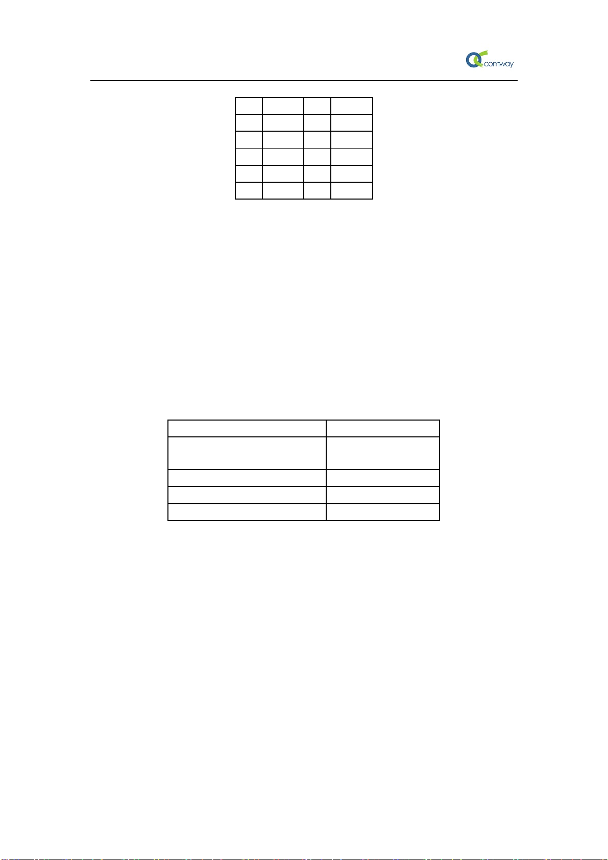
Pin Signal Pin Signal
1 6
2 RXD 7
3 TXD 8
4 9
5 GND
1.4 Connecting the Power
Connect the 5 to 16 VDC power cord with the WG8010 IP Modem's power input. If the
power is properly supplied, the "PWR" LED will glow a solid green color to indicate that
the system is ready.
1.5 LED Indicators
The LED indicators on the front panel of the WG8010 IP Modem are described in the
following table.
LED status Device Status
DATA LED blinking Data
transmission
PWR, LINK LED blinking Not registered
PWR blinking Net search
LINK LED Permanently on Online
2. Configure WG8010 with AT command
2.1 Determine which Com Port to Use
Step 1.On older computers, there is usually a built in Com port. This is normally Com1.
Step 2.If you are using a USB-to-serial converter, you will need to determine which Com port
it is installed on.
Note: If the USB-to-serial converter has not been installed, install the necessary
drivers per the instruction supplied by your USB-to-Serial device. Then
leave the device unplugged.
Step 3.Open up the System Properties window. This is done through the Control Panel
→System or right-click on My Computer and select Properties. Select the
Hardware Tab.
Step 4.Select the Device Manager button. Expand the Ports section by selecting the + sign


