Concept Smoke Screen TITANIUM Ti70 User manual

TITANIUM Ti70/Ti100/Ti150
INSTALLATION AND OPERATION
MANUAL
VERSION: 28 November 2019

Thank you for purchasing a Concept Smoke Screen Titanium system. Your
choice to protect your property and premises with this equipment has given
you the use of one of the most effective security systems currently available.
Concept Smoke Screen systems have been in service for over 35 years and
have protected many millions of pounds worth of property, defeating criminals
and securing premises on an almost daily basis.
The Titanium line in particular is home to some incredibly sophisticated and
flexible security fog generators, borne from years of development and
refinement.
Please take the time to read and understand this guide to ensure you achieve
the maximum performance from your Smoke Screen. If you have any
questions that remain unanswered, please call our experts at Concept Smoke
Screen and we will help. Once again, thank you for your decision; we hope
that it’s one that never needs to be tested.
Matt Gilmartin, Managing Director
2

CONTENTS
1
General
1.1
1.2
1.3
1.4
1.5
Safety instructions………………………………………………………………………………………………………...…..
How does your Smoke Screen work?……………………………………………………………………………..
Introduction………………………………………………………………………………………………………………………..
Overview…………………………………………………………………………………………………………………………….
Typical installations…………………………………………………………………………………………………............
4
4
5
5
6
2
Location
2.1
2.2
2.3
2.4
2.5
Positioning………………………………………………………………………………………………………………………….
Installation process…………………………………………………………………………………………………………...
Access………………………………………………………………………………………..……………………………………..
Mounting………………………………………………………………………………………………………………..…………..
Nozzle changing……………………………………………………………………………………………………….……….
7
8
8
9
11
3
Function
3.1
3.2
Controlling the smoke……………………………………………………………………....………………………………
Outputs……………………………………………………………………………………….……………………………………..
12
13
4
Connections
4.1
4.2
Circuit board layout…………………………………………………………………………………………………………..
Generic connection diagram……………………………………………………………….……………………………
14
15
5
Settings
5.1
5.2
5.3
5.4
5.5
5.6
Isolate (Servicing) mode……………………………………………………………………………………………...……
Tamper………………………………………………………………………………………………………………….……………
Fluid management………………………………………………………………………….…………………………………
Battery management……………………………………………………………………….………………………………..
Monitoring and control over IP and serial bus…………………………………………...…………………...
Programming……………………………………………………………………………………………………………………..
16
16
17
18
19
21
6
Commissioning
6.1
Testing………………………………………………………………………………………………………………………………..
32
7
Servicing
7.1
7.2
7.3
7.4
LED and sound indications…………………………………………………………………………………….………...
Thermal cut out (TCO) reset………………………………………………………………………………….………….
Action after every activation…………………………………………………………………..…………………………
Servicing and fluid replenishment……………………………………………………………………………………
33
34
35
35
8
Miscellaneous
8.1
8.2
8.3
FAQ…………………………………………………………………………………………………………………………………...
Installer notes……………………………………………………………..……………………………………………………..
WEEE End of Product Life………………………………………………………………………………………………...
36
37
38
3

General
1
1.1 SAFETY INSTRUCTIONS
Before installing and using the Smoke Screen read, follow and retain this manual and safety instructions for future
reference.
To reduce the risk of severe injury or death to persons, or damage to the Smoke Screen:
●Do not work on the Smoke Screen unless qualified by the manufacturer to do so.
●Disconnect the mains power supply before working in the heater block compartment or anywhere that mains
voltage is indicated by the warning labels shown below.
●Install in accordance with the instructions in this manual.
●Operate the Smoke Screen only from the type of power source indicated on the label.
●Do not modify the Smoke Screen.
●Adjust only the controls specified in this manual.
●Use only consumables and replacement parts specified by the manufacturer.
●Do not spill liquid of any type on, or inside, the Smoke Screen.
The following signs, or a variation, may be used for safety notices in this manual or on the Smoke Screen:
This type of warning note is
used to indicate possible
electrical shock hazards that
may cause serious injuries or
death.
This type of warning note is
used to indicate the possibility
of injury caused by hazards
other than electrical shock.
1.2 HOW DOES YOUR SMOKE SCREEN WORK?
Your Smoke Screen passes a non-toxic fluid through an efficient heat exchanger to create smoke, or more accurately
a thermally generated fog that obscures visibility, discouraging intruders from entering your premises.
This fog is very persistent and will stay suspended in the room for a significant length of time until it is vented by
opening the doors and windows.
The Smoke Screen uses a sophisticated electronic control system to ensure it heats up to, and maintains, its ideal
operating temperature using a minimal amount of electricity.
The control system similarly provides a flexible interface with intruder detectors, alarm systems and remote
monitoring centres to ensure that you are always protected and free of inadvertent activations.
4
WARNING CAUTION

1.3 INTRODUCTION
This manual covers the Titanium line of products.
Before commencing installation of the Smoke Screen ensure that you have all of the following equipment supplied in
the box:
●1 x Smoke Screen.
●1 x Mounting bracket.
●1 x Swift-Fit fluid reservoir.
●2 x 12v batteries.
●1 x literature pack and warning sign.
●1 x Extra 30-degree Nozzle for wall mounted installation.
You will also need:
●Mains power supply ; an unswitched 13 amp fused spur connected to dedicated breaker.
●Connections into the alarm panel or other triggering system.
●PIR (or equivalent) to provide the hold-off where required.
●Optionally a Screen Sensor for top-up functionality.
1.4 OVERVIEW
The Smoke Screen is designed to form part of an existing intruder alarm system but may also be configured as a
‘stand-alone’ system or as part of a centrally monitored, command and control system. A typical installation is shown
in the following schematic:
5

1.5 TYPICAL INSTALLATIONS
A Smoke Screen system can be installed in many ways; the following are outlines of typical installations
(an Alarm Panel Control system is generally used for illustration in this manual):
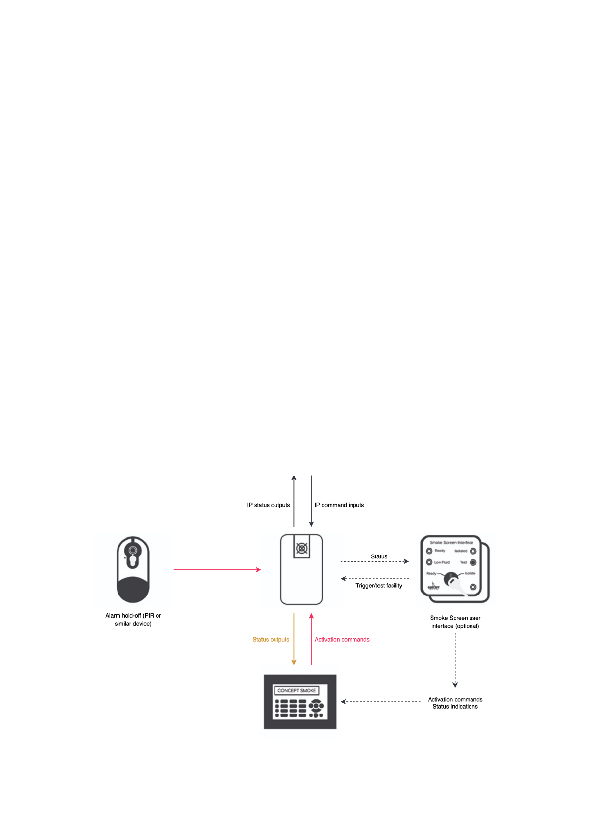
Alarm Panel Control
●The Smoke Screen is wall or ceiling mounted in the appropriate location.
●A Hold-off PIR (or similar device) located within the same area as the Smoke Screen providing a
confirmation signal to the Smoke Screen to start, or restart, ‘smoke’ production.
●A Set command supplied by an alarm control panel, or equivalent, in the form of an N/C (normally
closed) or an N/O (normally open) relay changing state when the alarm system is set for operation.
●A Trigger command supplied by the alarm control panel, or equivalent, in the form of an N/C
(normally closed) or an N/O (normally open) relay changing state when the alarm system confirms
an intruder alert.
Local Network Monitoring
●The Smoke Screen is wall or ceiling mounted in the appropriate location.
●Typically, the Smoke Screen would be integrated with an alarm panel or similar controlling system
as above.
●The Smoke Screen is assigned a fixed or reserved IP address and attached to the local network.
●The addition of the TitanConfig program running on the same network will allow diagnostic and
configuration control from a Windows-based platform.
Remote Network Monitoring and Control
●The Smoke Screen is wall or ceiling mounted in the appropriate location.
●The Smoke Screen may be integrated with an alarm panel and/or commanded from a central
location over IP.
●The Smoke Screen is assigned an IP address on the local network and communicates with a
centralised remote server using ports 161 & 162.
●The Smoke Screen may be controlled using any third party platform integrated with TitanServer or
through the Titanium247 cloud-based monitoring and control platform. Finally, engineering control
and diagnostics are offered through TitanConfig.
6

Location
2
2.1 POSITIONING
The Smoke Screen should ideally be sited in a covert position away from prying eyes and thereby reducing the
possibility of tampering or an attack. The ideal place for the Smoke Screen is above a ceiling from where the smoke
plume is used to its best effect, bursting on the ground and spreading outwards and upwards through 360°. If no
suitable ceiling location is available then the next best location is a wall mounting close to ceiling.
Wall-mounting
The optimum wall mounting position for the Smoke Screen is 2.5 metres above the floor facing the area to be
protected and using an appropriate angle nozzle. The maximum recommended mounting-height above floor level is
3 metres, the minimum is 1 metre and there should be no obstacles within 1 metre of the smoke output nozzle. Also,
leave a minimum of 150mm clearance to the ceiling.
Ceiling-mounting
The optimum wall mounting position for the Smoke Screen is 2.5 metres above the floor facing the area to be
protected and using an appropriate angle nozzle. The maximum recommended mounting-height above floor level is
3 metres, the minimum is 1 metre and there should be no obstacles within 1 metre of the smoke output nozzle.
7

2.2 INSTALLATION PROCESS
1. Site the Smoke Screen, fix to the wall or ceiling as appropriate.
2. Make connections as required to the control system, i.e. Alarm Panel and Hold-off PIR.
3. Make connection to the Smoke Screen Interface (if used) and set the key switch to isolate.
4. Connect and turn on the mains power.
5. Turn on the internal battery back-up.
6. The Smoke Screen will heat up to operating temperature in approximately 20 minutes.
7. Make relevant programming settings and set smoke timing for the specified room size.
8. Insert a Swift-Fit fluid reservoir.
9. Make sure all tamper switches are closed.
10. If fitted set the Smoke Screen Interface key switch to ‘Ready’ and you are ready for test.
2.3 ACCESS
To access the PCB connections, programming panel and mounting holes (battery and fluid access is
covered in the relevant sections) remove the front cover by unscrewing the set screws on either side and
unhooking it from the top of the case; refitting is the reverse process. Installation cable entry is through the
serrated grommet on the left back of the case.
8

2.4 MOUNTING
The Smoke Screen can be mounted on a ceiling or a wall using the simple standard bracket supplied with
the unit. This flush-fitting bracket maximizes security by concealing all the mounting fastenings such that
they can only be accessed, or the Smoke Screen dismounted, by dismantling the unit. Moreover, the
Smoke Screen has a tamper protection switch to provide an alert in the unlikely event that it is disturbed.
In all cases, the installer must attach the Smoke Screen to the building structure using appropriate
fasteners.
NB: When mounting the Smoke Screen ensure that the airflow through the vent holes in the rear of the
unit is not obstructed.
Wall and ceiling mounting
Ceiling or wall mounting is the same process except that rather than fixing the Smoke Screen direct to a
ceiling an intermediate unistrut section may be used or it can be suspended as described in the next
section.
Attach the bracket to the wall or
ceiling using appropriate fixings.
Carefully hook the slots on the back
of the Smoke Screen onto the
bracket (for clarity, shown above not
attached to the ceiling/wall). Slide
along to align the screw fixing holes.
The unit will now hang on the
bracket.
Fit, and ensure tight, 2 x M6 set
screw with washer in the hole in the
back of the Smoke Screen alongside
each of the two mounting slots.
Access to the fixing holes is through
the fluid and heater block
compartments.
9

Suspension mounting
Suspending the Smoke Screen is achieved using a ‘Suspension Kit’ comprising a length of unistrut, two
sections of threaded bar and fixings.
Suspension Kit Contents (all M8)
Unistrut 1 x 1 metre
Threaded bar 2 x 1 metre
Fixings:
1 x ceiling hole surround
2 x drop-in anchors
6 x full nuts
4 x 25mm washers
2 x 38mm washers
2 x channel nuts
Prepare the Smoke Screen by fitting
the angle brackets. Fix the required
length of M8 threaded bar to the
bracket using 4 x nuts and 4 x 25mm
washers.
Fix the unistrut into place. There are
a range of fixings to accommodate
concrete ceiling, girders etc.; if in
doubt contact the fixing supplier.
Attach the threaded bar to the
unistrut using the channel nuts,
38mm washers and M8 nuts. Once
this is done the Smoke Screen can
be lifted into position and the set
screws tightened as above.
Any fine adjustments can be made at
this stage as the nuts and the
threaded bar will take the weight of
the Smoke Screen.
The final assembly, viewed ‘through
the ceiling’ is in the photo. Any hole
made to allow smoke through a
suspended ceiling below the Smoke
Screen can be made good with a
cosmetic hole surround.
10

2.5 NOZZLE CHANGING
To change the nozzle, first remove the front cover then remove and replace the nozzle using a 12mm ring
spanner. Always use a new copper sealing washer and ensure that an angled nozzle is seated in the
correct orientation. The Smoke Screen is delivered with a single-hole straight nozzle and the following are
also available – 2-hole horizontal, 3-hole horizontal, 1-hole 30° angle down and 2-hole 30° angle down.
Be aware of high
voltage in the block
area. The electrical
supply should be
switched off before
working in the heater
block compartment.
This operation is usually
carried out during
installation. If the Smoke
Screen has been in
service the nozzles will
be extremely hot and
will cause injury if
touched. Therefore, the
Smoke Screen should
be switched off and time
should be allowed for
the nozzles to cool.
11
WARNING CAUTION

Function
3
3.1 CONTROLLING THE SMOKE
Inputs
There are 6 sets of input control connections on the Smoke Screen that control activation - Alarm Set (Z1), Trigger
(Z2), Top-Up (Z3), Hold Off (Z4), Panic (Z5) and Isolate (Z6). These input pins should be connected to the PCB Ground
through clean contacts and can be programmed to “Normally closed”, “Normally open”, a variety of EOL resistance
settings or “NOT USED”.
Starting an activation
The Smoke Screen will produce ‘smoke’ in the following 3 circumstances:
1. The three connections normally used in an installation, i.e. Alarm Set (Z1), Trigger (Z2), and Hold Off (Z4) (if
selected to on) must all be in alarm.
2. The Panic (Z5) connection must change state from restore to an alarm condition. This input is an edge input
and will not trigger a generator if it is already in its alarm condition when the generator reaches a “ready”
state.
3. The Alarm Set (Z1) and a tamper are in alarm.
Stopping an activation
Once activated the Smoke Screen will stop producing ‘smoke’ before the end of the programmed smoke time only if
the Alarm Set (Z1) is selected to a non-alarm state; in the event of a panic activation it is necessary to cycle the Alarm
Set (Z1) to “on” then “off”. If ‘Hold-Off’ is closed during an activation the Smoke Screen will continue to produce
smoke for the set Smoke Time.
Re-triggering smoke
If, after it has made smoke for the set time and reached the end of it’s programmed “Smoke on” time, the Smoke
Screen receives another hold-off alarm while both ‘Set’ and ‘Trigger’ inputs remain open, it will ‘re-trigger’ and make
smoke again. The re-trigger smoke time and the number of repeats are set in the Installer menu.
Preventing an activation
To prevent the Smoke Screen from making smoke under any circumstances:
●Select Isolate to “On” in the Installer menu
or
●Select the programmable input Z6 to “Isolate”
12

3.2 OUTPUTS
Clean contact outputs are provided for connection to the Alarm Panel for ‘Ready’, ‘Tamper’, ‘Battery
Failure’, ‘Mains Failure’, ‘Fluid Low’, ‘Fluid Empty’, ‘Making Smoke’.
There are also 3 programmable clean contact outputs (PGM 1, PGM 2 and PGM 3) that can be set to follow
various functions (see the section on Programming for details).
13

Connections
4
4.1 CIRCUIT BOARD LAYOUT (PCB v2)
4.2 GENERIC CONNECTION DIAGRAM
The Smoke Screen can be programmed to use “Normally closed”, “Close = Alarm”, or a variety of EOL
resistance configurations (used to detect tampers on the circuits); for clarity, the diagram below uses
“Normally closed” connections. EOL resistors are fitted as usual between the relevant pin and ground
when used.
14

Settings
5
5.1 ISOLATE (SERVICING) MODE
To prevent the Smoke Screen from making smoke whilst work is conducted with power applied it can be
put into a servicing mode by selecting the “Isolate” function at the start of the Installer Configuration Menu
to ‘on’.
FAILURE TO DISABLE ISOLATE WHEN NO LONGER REQUIRED WILL PREVENT THE SMOKE SCREEN
OPERATING.
5.2 TAMPER
There are 4 internal tamper circuits on the Smoke Screen, one on each cover (front, battery and fluid) and
one through the rear of the case for a bracket tamper. There is also an external tamper input on the PCB
for the monitoring of peripheral devices. On a tamper alarm the Smoke Screen provides an output
indication of the event and automatically activates if the Zone 1 (Set) is in alarm. If the Smoke Screen is not
mounted on its bracket the bracket tamper should be by-passed to prevent unwanted tamper warnings.
The LCD display and control buttons are disabled if the front tamper is closed.
16

5.3 FLUID MANAGEMENT
The Smoke Screen has a replaceable 1 litre Swift-Fit fluid reservoir (also known as product code SFL-1000)
that is accessed by removing the cover on the right-hand side of the unit. The fluid level is monitored
using sensors in the fluid reservoir to give a “Low Fluid” indication output when the Swift-Fit is
approximately 50% full and an “Empty Fluid” output when the bottle is empty. The Smoke Screen will not
produce fog when there is an “Empty Fluid” indication.
Fluid Replenish
Obtain a replacement fluid reservoir from your Smoke Screen supplier. Open the right-hand access panel.
Lift the reservoir out of the compartment by removing the lower end first (see photo below). Disconnect
the fluid monitoring cable and the fluid feed pipe (pull collar to release). Refitting the reservoir is the
reverse of the removal process.
17

5.4 BATTERY MANAGEMENT
Operation
The Smoke Screen is fitted with a battery to provide power to the electronic circuits and pump (not to the
fluid heater) in the event of a mains power failure. This ensures that the Smoke Screen can provide an
effective activation for at least 1 hour after a mains power failure (further detail is on the relevant Smoke
Screen datasheet). The Smoke Screen is capable of activating in the event of a battery fault or if the
batteries are not fitted. The Smoke Screen is supplied with a set of batteries but they are not fitted on
delivery. Replacement batteries may be obtained from your Smoke Screen installer or Concept Smoke
Screen.
Removal and replacement
To remove the batteries, open the access panel on the left side of
the Smoke Screen. Slide out the old batteries and replace with new
units ensuring that the battery is upright and the contacts enter the
battery compartment first.
Battery switch
The Smoke Screen has a switch in the battery compartment to
permit the batteries to be disconnected from the system whilst
remaining in place. The delivery setting is “Off”. Select to “On” if
intending to use the battery facility.
THE SMOKE SCREEN WILL NOT FUNCTION AT ALL DURING A
MAINS POWER FAILURE IF THE BATTERIES ARE NOT FITTED OR
ARE DISABLED.
18

5.5 MONITORING AND CONTROL OVER IP AND SERIAL BUS
All Titanium generators are equipped with an advanced electronics control and communication package.
This allows remote commands and control using the two features available.
●SNMPv3 communication over Ethernet / IP and Internal RS485.
●Master and slave machines over the RS485 serial bus is possible.
These communications features can be used in the following ways:
5.5.1 SNMPv3
SNMPv3 IP communication allows the Smoke Screen to be fully integrated with any PSIM solution which
supports this protocol. Additionally, connection to a dedicated SmokeNet server or Via the Titanium247
cloud monitoring platform gives full control & monitoring capability of the Smoke Screen system.
It is also possible for Smoke Screen installers to remotely diagnose and configure any Titanium systems
using the Titanium Config Tool.
IMPORTANT! - When making changes to the DHCP setting or any IP addresses, the system must be
rebooted for the selected programming to be accepted. To reboot the system choose “restart system” in
the installer menu. Select “yes” by pressing enter - the system will now reboot itself.
19

5.5.2 RS485
When this is utilized, one Smoke Screen can be set as the master system which will then control up to 9
slaves on the same bus. It is possible to chain many more using a dedicated controller from Concept
Smoke Screen.
When making use of this feature, the following things become true:
1. The master SSM operates as a global input and output point for the controlling alarm system
(where used).
In this scenario, any attached slave system that develops a local fault, will trigger a global fault at
the master.
The slaves will follow the “Set” and “Trigger” status of the master and will then operate when they
detect movement on a locally attached hold off detector. If “hold-off chain” is selected on the
master, a slave that detects a hold off alarm, will pass the signal to all attached generators
(including the master) and the whole system will trigger.
Equally, if “Panic propagate” is selected at the master, a triggered panic input at the master or any
attached slave, will trigger the whole chain. When this is de-selected, each panic input will operate
only the SSM it is attached to.
2. The master generator is capable of providing full information over a serial connection relating to
the condition of itself and all of the attached slaves to TitanConfig. This can then be displayed as a
wall of information providing easy visual information of the entire system. See TitanConfig manuals
for more information on this feature.
3. It is not possible to have 2 masters on the same bus – each assignment must be unique.
20
This manual suits for next models
2
Table of contents
Other Concept Smoke Screen Security System manuals