Condair Omega Pro User manual

SERVICE MANUAL
2588797-C EN 2011
Humidication and Evaporative Cooling
Steam generator
Condair Omega Pro

Proprietary Notice
This document and the information disclosed herein are proprietary data of Condair Group AG. Neither this docu-
ment, nor the information contained herein shall be reproduced, used, or disclosed to others without the written
authorization of Condair Group AG, except to the extent required for installation or maintenance of recipient's
equipment.
Liability Notice
Condair Group AG does not accept any liability due to incorrect installation or operation of the equipment or due
to the use of parts/components/equipment that are not authorized by Condair Group AG.
Copyright Notice
© Condair Group AG, All rights reserved.
Technical modications reserved.

3Contents
Contents
1 Introduction 5
2 For your safety 6
3 Factory settings 8
3.1 Factory settings in "Factory" submenu 8
3.1.1 Determining unit settings 9
3.1.2 Determining unit settings 10
3.1.3 Reset unit to factory default 12
3.1.4 Determining the countdown function for the blocking of the Condair Omega Pro 12
3.2 Factory functions in the "Service" submenu 13
3.2.1 Reset fault and service history 13
3.2.2 Output diagnostic functions 14
4 Operational malfunctions 16
4.1 W5 - Extension unit missing 16
4.2 W6 - Main unit missing 17
4.3 E10 – Reset Integrated controller 18
4.4 W20/E20 - External safety loop open or interrupted 19
4.5 E22 - Maximum lling time exceeded 20
4.6 E26 – Main contactor jammed 21
4.7 W28 - Small maintenance due 22
4.8 W29 - Extended maintenance due 23
4.9 W32 - Humidity sensor signal interrupted 24
4.10 E34 - Maximum drain time exceeded 25
4.11 W35 - BMS Timeout 26
4.12 E47 - Invalid level detected 27
4.13 E52 - Unstable level 28
4.14 E54 – Leak sensor 29
4.15 E56 - Internal safety loop interrupted 30
4.16 E58, E60, E61, E62 and E73 30
4.17 E74 - Keep Alive signal missing 31
4.18 E80 - USB Logger fault 32
4.19 E82 - Driver missing 33
4.20 E83 - Driver board address of extension unit wrong 34
4.21 E84 - Driver board unspecic 34
4.22 E85 - Product ID of driver board wrong 35
4.23 E86 - Wrong version of driver board 35
4.24 E87 / E88 / E89 – Driver local supply voltage 36
4.25 E90 36
4.26 E95 - Heating voltage missing 37
4.27 E97 / E98 - 24 V/10 V output of driver board out of admissible range 38
4.28 E100 - Fault state on output driver of inlet valve 1 39
4.29 E101 - Fault state on output driver of inlet valve 2 40
4.30 E111 - Fault state on output driver of optional drain water cooling valve 41
4.31 E112 - Fault state on output driver of optional scale collector drain valve 42

4Contents
4.32 E120 - Fill time minimum 43
4.33 E121 - Maximum vaporization time exceeded 44
4.34 E124, E200, E201 and E210 45
4.35 W300 - Safety loop blower pack open 46
5 Notes on unit components and functions 47
5.1 Main electronic components 47
5.2 Unit versions 47
5.3 Control signals 48
5.4 Heating control Condair Omega Pro 49
5.4.1 Steam demand and heating assemblies Condair Omega Pro 49
5.5 Level unit 51
5.6 Fill and drain sequences 51
5.6.1 Fill and drain states on the Basic unit 51
5.6.2 Fill and drain states on the Basic unit with option P 52
5.7 Level controlled drain 52
5.8 Idle Drain 53
5.9 Timer controlled drain 53
5.10 Service interval times and reduction time 54
5.10.1 Manual input of the service interval times and reduction time 54
5.10.2 Calculated service interval and reduction time 55
5.10.2.1 Nominal values for the equations 55
5.10.2.2 Denitions 56
5.10.2.3 Equations for the calculation of the maintenance and reduction intervals 57
5.10.2.4 Calculated service interval examples 57
5.11 SIM card 59
5.11.1 The integrated controller starts with a new, empty SIM card 59
5.11.2 The serial number of the SIM card and the integrated controller are identical 59
5.11.3 The serial number of the SIM card and the integrated controller are not identical 59
5.11.4 Replacing the integrated controller board and using the existing SIM card 60
6 Appendix 63
6.1 Condair Omega Pro 400 V standard unit wiring 63
6.2 Connection of the Condair RO-A pure water system to the Condair Omega Pro
(Condair Omega Pro integrated systems) 64
6.2.1 Wiring diagram Condair RO-A - Condair Omega Pro 64
6.2.2 Connecting Condair Omega Pro type units to the Condair RO-A 66

5Introduction
1 Introduction
The present service manual is meant for the trained Condair service technician and assumes a profound
knowledge on the Condair Omega Pro. It is also assumed that the Service technician has notice of the
installation manual and operation manual of the Condair Omega Pro and that he is familiar with the
dangers when working on the unit.
The present service manual includes the following information:
– Description of the settings in the factory level of the Condair Omega Pro control.
– Information on operational malfunctions
– Notes on unit components and functions
Symbols used in this manual
CAUTION!
The catchword "CAUTION" used in conjunction with the caution symbol in the circle designates notes
in this service manual that, if neglected, may cause damage and/or malfunction of the unit or other
material assets.
WARNING!
The catchword "WARNING" used in conjunction with the general caution symbol designates safety
and danger notes in this service manual that, if neglected, may cause to injury to persons.
DANGER!
The catchword "DANGER" used in conjunction with the general caution symbol designates safety
and danger notes in this service manual that, if neglected, may lead to severe injury or even death
of persons.

6For your safety
2 For your safety
General
The service technician working with the Condair Omega Pro must have read and understood the present
service manual as well as the installation manual and the operation manual of the Condair Omega Pro
before carrying out any work.
Knowing and understanding the contents of the service manual as well as the installation manual and the
operation manual of the Condair Omega Pro is a basic requirement for protecting the personnel against
any kind of danger, to prevent faulty operation, and to operate the unit safely and correctly.
Qualication of personnel
All work described in this service manual must only be carried out by trained Condair service tech-
nicians.
It is assumed that the service technicians working with the Condair Omega Pro are familiar and comply
with the appropriate regulations on work safety and the prevention of accidents.

7For your safety
Danger that may arise from the Condair Omega Pro steam generator
DANGER!
Danger of electric hazard!
The Condair Omega Pro is mains powered. Live parts may be exposed when the unit is open.
Touching live parts may cause severe injury or danger to life.
Prevention: Before carrying out any work set the Condair Omega Pro out of operation (switch off the
unit, disconnect it from the mains and stop the water supply) and secure the unit against inadvertent
power-up.
WARNING!
Hot water vapour - Danger of scalding!
The Condair Omega Pro produces hot water vapour. There is danger of scalding when coming
in contact with hot water vapour.
Prevention: Do not carry out any work on the steam system during operation (steam lines, steam
distributor, blower pack, etc.). If the steam system is leaky set the Condair Omega Pro immediately
out of operation (switch off the unit, disconnect it from the mains and stop the water supply) and
secure the unit against inadvertent power-up. Correctly seal the steam system before putting the unit
into operation again.
WARNING!
Danger of burning!
During operation the components of the steam system (steam cylinder, steam distributor, etc.)
get very hot (up to 100 °C). There is danger of burning when touching the hot components.
Prevention: Before carrying out any work on the steam system set the Condair Omega Pro out of
operation (switch off the unit, disconnect it from the mains and stop the water supply) and secure the
unit against inadvertent power-up. Then, wait until the components have cooled down sufciently thus
preventing danger of burning.

8Factory settings
Password: 1055
3 Factory settings
With the factory password "1055" you may access the factory settings in the "Factory" submenu as well
as the factory functions in the "Service" submenu.
3.1 Factory settings in "Factory" submenu
• Select the "Factory" submenu as shown below.

9Factory settings
3.1.1 Determining unit settings
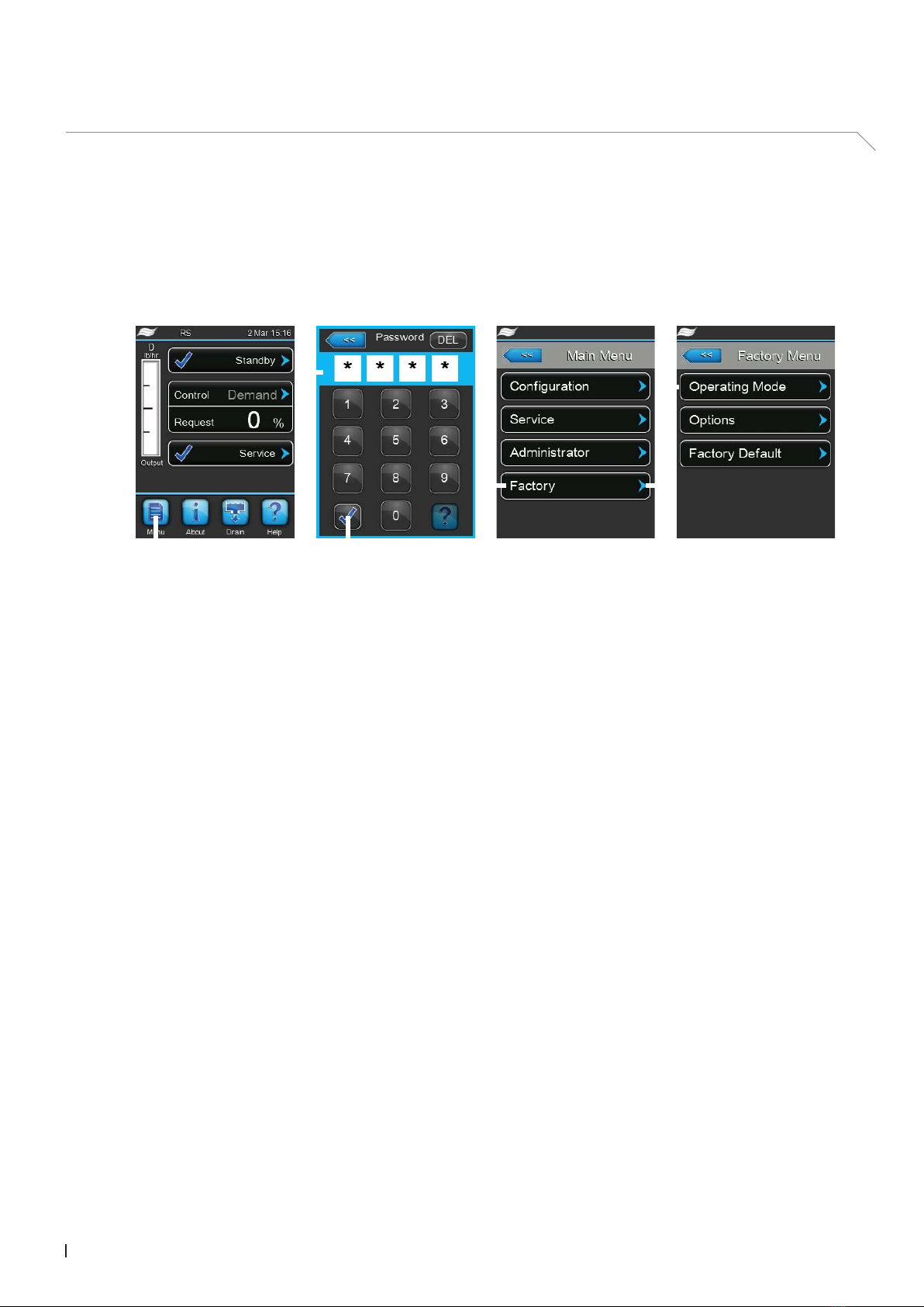
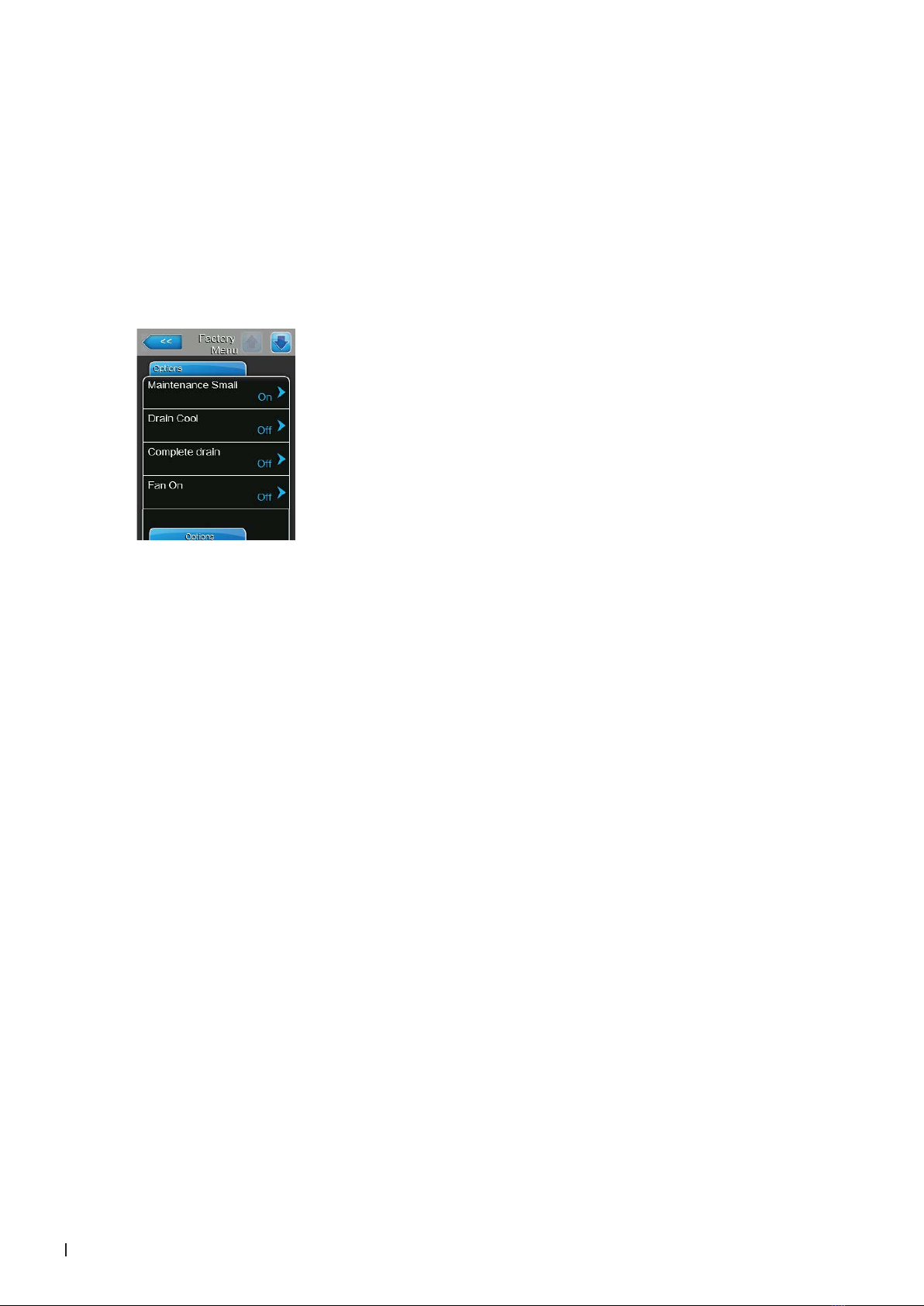
• In the "Factory" submenu press on the <Operating Mode> button. The unit settings parameter ap-
pear.
– Brand: With this setting you determine the brand name of the steam
generator.
Factory setting: Condair CE
Options: Condair CE (European version)
Condair UL (Amercian version)
Condair Spa (Spa version)
Attention: When you change the brand, the associated passwords
are also changed!
– Mode: With this setting you determine whether the controller is congured
to control the Condair Omega Pro only ("RS"), the Condair Omega Pro
with optional reverse osmosis system ("RS+RO") or the optional reverse
osmosis system only ("RO").
Factory setting: RS
Options: RS (congured to control the Condair Omega Pro
control only)
RS+RO (congured to control the Condair Omega
Pro control with optional reverse osmosis system)
RO (congured to control the optional reverse osmosis
system only)
– Nominal Voltage: With this setting you determine the heating voltage of
the of the steam generator.
Factory setting: 400V
Options: 200V, 208V, 230V, 240V, 380V, 400V, 415V,
440V, 460V, 480V, 500V, 550V, 600V
– Nominal Capacity: With this setting you determine the nominal steam
capacity of the steam generator.
Factory setting: 5kg/10lbs
Options: 5kg/10lbs, 8kg/15lbs, 10kg/20lbs, 16kg/30lbs,
20kg/45lbs, 24kg/53lbs, 30kg/65lbs, 40kg/90lbs,
50kg/110lbs, 60kg/130lbs, 70kg/550lbs,
80kg/180lbs
– Flicker Correction: With this setting you determine a icker Gradient to
adjust the factory set icker time.
Important: icker regulations are only complied if the "Consider icker
rule" function in the unit settings of the user level is set to "On" and the
icker Gradient is set ≥2.0.
Factory setting: 2.0
Setting range: 0.1 ... 4.0
– Evaporation correction: With this setting you determine a factor to mul-
tiply the minimal demand threshold of the evaporation monitoring. See
also fault description E121 in chapter 4.33.
Factory setting: 2.0
Setting range: 1.0 ... 5.0

10 Factory settings
3.1.2 Determining unit settings
• In the "Factory" submenu press on the <Options> button. The optional settings parameter appear.
– Maintenance Small: With this setting you determine whether the mainte-
nance counter for the small maintenance is activated ("On") or not ("Off").
Factory setting: dependent on unit type (with or without scale
collector tank)
Options: On (on units with scale collector tank) or Off (on units
without scale collector tank)
– Drain Cool: With this setting you can activate ("On") or deactivate ("Off")
the software function for the optional drain cooling if the Condair Omega
Pro is equipped with the optional drain cooling.
Factory setting: Off
Options: On (drain cooling activated) or
Off (drain cooling deactivated)
– Complete Drain: With this setting you can activate ("On") or deactivate
("Off") the software function for the optional scale collector tank drain valve
for draining the scale collector tank.
Factory setting: Off
Options: On (optional scale collector tank drain valve acti-
vated) or
Off (optional scale collector tank drain valve activated)
– Fan On: With this setting you can activate ("On") or deactivate ("Off")
the software function for the control of a fan of the AHU via the optional
accessory board.
Factory setting: Off
Options: On (fan control function activated) or
Off (fan control function deactivated)
– Unit stop: Fill time E22: With this setting you determine whether the
steam generator should be blocked after the max. lling time is exceeded
("On") or if it should keep trying to recover ("Off").
Factory setting: Off
Setting range: On
Off

11Factory settings
– Hygiene Flush: With this setting you can activate ("On") or deactivate
("Off") the water supply line ushing function.
Factory setting: Off
Options: On (water supply line ushing function activated) or
Off (water supply line ushing function deactivated)
– Int.-/Ext. Valve: With this setting you determine whether the ushing of
the water supply line is established via the optional internal drain water
cooling valve ("Internal Valve") or the optional external ushing valve
("External Valve").
Note: This menu item appears only if the water supply line ushing func-
tion is activated.
Factory setting: Internal Valve
Options: Internal Valve (ushing is established via the op-
tional internal drain water cooling valve) or
External Valve (ushing is established via the
optional external ushing valve)
– Digital Input J8: With this setting you determine whether the digital signal
input J8 is deactivated ("Off) or wether it shall be used for leakage moni-
toring ("Leakage Sensor") or for the external triggering of a drain cycle
("External Drain").
Note: if the digital signal input J8 is set to "Leakage Sensor" a leakage
alarm is triggered, if the contact opens. If the digital signal input J8 is set
to "External Drain" a drain cycle is triggered, if the contact is closed.
Factory setting: Off
Options: Off (the digital signal input J8 deactivated) or
Leakage Sensor (the digital signal input J8 is
used for leakage monitoring) or
External Drain (the digital signal input J8 is used
for external triggering of a drain cycle)

12 Factory settings
3.1.3 Reset unit to factory default
• In the "Factory" submenu press on the <Factory Default> button, and select the "Factory Default"
tab.
– Reset Serial Number: After selecting the function a conrmation dialogue
appears where you can conrm the reset of the serial number or cancel
the procedure. After switching the unit off and on again a dialogue appears
where you have to enter the serial number of the unit (see rating plate).
All settings and operating hours are retained ( ATTENTION, only valid
from software version 5.6.x.xx).
3.1.4 Determining the countdown function for the blocking of the Condair Omega Pro
• In the "Factory" submenu press on the <Factory Default> button, and select the "Countdown" tab.
– Code: With this setting you can activate the countdown function. If the
countdown function is activated you have to enter a four digits code. With
that code you can unlock the Condair Omega Pro after the countdown
has elapsed and the fault message "E15 - Program fault" is shown.
Factory setting: Off
Options: Off – countdown function is deactivated.
On – countdown function will be activated. After-
wards a four digits unlock code must be entered.
CAUTION!
Note the entered code. If the code gets lost you are not able to
unlock the Condair Omega Pro anymore.
– Time: With this setting you determine the countdown time in days.
Factory setting: 30 days
Setting range: 1 …120 days

13Factory settings
3.2 Factory functions in the "Service" submenu
• In the main menu press on the <Service> button as shown below.
3.2.1 Reset fault and service history
• Select in the "Service" submenu the "Fault/Service History" tab.
Note: the functions "Reset Fault History" and "Reset Service History" are shown only, if the menu
has been accessed with the factory password "1055".
Password: 1055
– Reset Fault History: with this function you can reset the fault history list.
After pressing on the "Reset Fault History" button a conrmation window
appears where the resetting of the fault history list must be conrmed.
– Reset Service History: with this function you can reset the service history
list. After pressing on the "Reset Service History" button a conrmation
window appears where the resetting of the service history list must be
conrmed.

14 Factory settings
3.2.2 Output diagnostic functions
• Select in the "Service" submenu the "Diagnostic" tab.
Note: the menu item "Output Diagnostics" is shown only, if the menu has been accessed with the
factory password "1055".
The following output diagnostic functions for "Cylinder A" (and "Cylinder B", if applicable) are avail-
able after accessing the "Output Diagnostics" submenu.
– Control Select: With this function you can switch the humidity or demand
signal between voltage and current signal.
– Limit Select: With this function you can switch the humidity or demand
signal of the supply air limiter between voltage and current signal.
– Main Contactor: With this function you can switch on and off the main
contactor.
– Relay Pump AC: With this function you can switch on and off the relay
for the voltage supply of the drain pump.
– Relay Heat Group A2/1: With this function you can switch on and off the
contactor for heat group A2/1 (on basic unit only).
– Relay Heat Group A3/1: With this function you can switch on and off the
contactor for heat group A3/1 (on basic unit only).
– Heat Group A1/1: With this function you can switch on and off heat group
A1/1
– Heat Group A1/2: With this function you can switch on and off heat group
A1/2.
– Heat Group A1/3: With this function you can switch on and off heat group
A1/3.
– Heat Group A2/1: With this function you can switch on and off heat group
A2/1.
– Heat Group A3/1: With this function you can switch on and off heat group
A3/1.
– Inlet 1: With this function you can open and close the inlet valve.

15Factory settings
– Inlet 2: With this function you can open and close the second inlet valve
on Option P units.
Note: On standard units this parameter has not function.
– Drain 1: With this function you can open and close the optional drain
cooling valve.
– Drain 2: With this function you can open and close the optional scale
collector tank drain valve.

16 Operational malfunctions
4 Operational malfunctions
4.1 W5 - Extension unit missing
Function: indicates that there is no connection between the main unit and the extension unit.
Procedure: if the connection between the main unit and the extension unit is lost, the system will be
blocked and the warning "W5" will be displayed. The warning display is automatically reset as soon as
a connection is available again.
Behaviour on activation:
Warning No Error
Error Message: W5: Ext Missing –
LED indication on unit: LED lights yellow –
Remote indication board: – –
Entry error history: – –
System: Unit blocked –
Time delay: – –
Reset: self-healing as soon as the con-
nection between the main unit and
extension unit is available again.
–
Diagnostic actions:
• Check Linkup cable connection between the main unit and the extension unit.
• Check whether the extension unit is switched on.
• Check Linkup software settings in the control software.

17Operational malfunctions
4.2 W6 - Main unit missing
Function: indicates that there is no connection between the extension unit and the main unit.
Procedure: if the connection between the extension unit and the main unit is lost, the system will be
blocked and the warning "W6" will be displayed. The warning display is automatically reset as soon as
a connection is available again.
Behaviour on activation:
Warning No Error
Error Message: W6: Main Missing –
LED indication on unit: LED lights yellow –
Remote indication board: – –
Entry error history: – –
System: Unit blocked –
Time delay: – –
Reset: self-healing as soon as the con-
nection between the main unit and
extension unit is available again.
–
Diagnostic actions:
• Check whether the main unit is turned on.
• Check Linkup cable connection between the main unit and the extension unit.
• Check Linkup software settings in the control software.

18 Operational malfunctions
4.3 E10 – Reset Integrated controller
Function: indicates that the Integrated Controller of the Condair Omega Pro has carried out an automatic
restart due to a software problem.
Procedure: If the Integrated Controller of the Condair Omega Pro detects a software problem that
makes continued operation impossible, the controller carries out an automatic restart. After the restart,
error message "E10" appears and the system is blocked.
Behaviour on activation:
No Warning Error
Error Message: – E10: CTRL Reset
LED indication on unit: – LED lights red
Remote indication board: – Error relay activated
Entry error history: –E10A
System: – Unit blocked
Time delay: – –
Reset: – Switch humidier Off and On
again.
Diagnostic actions:
• Reset the error message and check whether the Condair Omega Pro then works correctly again.
• If the error occurs repeatedly, carry out a software update.
• Replace the control board if necessary.

19Operational malfunctions
4.4 W20/E20 - External safety loop open or interrupted
Function: indicates that the safety loop is open.
Procedure: if the external safety loop is open the system is blocked and the warning message "W20" is
triggered. As soon as the safety loop is closed again the warning or error message is automatically reset.
Note: By setting the parameter "Safety Loop" in the "Communication" submenu in the user level to "Yes"
an open safety loop triggers the Error "E20" and the error relay is activated.
Behaviour on activation:
Warning
(Parameter "Safety Loop" in the
"Communication" submenu in the
user level is set to "No")
Error
(Parameter "Safety Loop" in the
"Communication" submenu in the
user level is set to "Yes")
Error Message: W20: Ext. safety loop E20: Ext. safety loop
LED indication on unit: LED lights yellow LED lights red
Remote indication board: – Error relay activated
Entry error history: –E20A
System: Unit blocked Unit blocked
Time delay: – –
Reset: self healing self healing
Diagnostic actions:
• Check all safety monitoring devices (e.g. ventilation interlock, high limit humidistat, air proving switch)
for correct function.
• Check wiring of safety loop connected to terminals "SC1" and "SC2" on driver board of module A.

20 Operational malfunctions
4.5 E22 - Maximum lling time exceeded
Function: indicates that the maximum lling time has exceeded. The maximum times are dened as
follows.
Capacity Maximum lling time
from level 0 to 1 from level 1 to 3 from level 3 to 4 from level 4 to 5
5 kg (10 lbs) 1500 s 240 s 180 s 180 s
8 kg (15 lbs) 1500 s 240 s 180 s 180 s
10 kg (20 lbs) 1500 s 240 s 180 s 180 s
16 kg (30 lbs) 1800 s 240 s 180 s 180 s
20 kg (45 lbs) 1800 s 240 s 180 s 180 s
24 kg (52 lbs) 1800 s 240 s 180 s 180 s
30 kg (65 lbs) 1800 s 240 s 180 s 180 s
40 kg (90 lbs) 1800 s 240 s 180 s 180 s
Procedure: the Condair Omega Pro monitors the lling process with different levels. If a level is not
reached within the preset time (see table above) warning message "W22" is triggered and the heating is
blocked as soon as the level drops below level 1 (level red). However the lling process is not stopped.
If the next level is still not reached within 30 minutes, the error message "E22" will be triggered and the
unit is blocked.
Behaviour on activation:
Warning Error
Error Message: W22: Max. ll time E22: Max. ll time
LED indication on unit: LED lights yellow LED lights red
Remote indication board: – Error relay activated
Entry error history: – E22A(B)
System: Heating is blocked Unit blocked
Time delay: 30 minutes 30 minutes
Reset: self healing if next level is reached If parameter "Unit stop: Fill time E22"
in the factory level is set to "On":
Switch Condair Omega Pro Off and
On again.
If parameter "Unit stop: Fill time E22"
in the factory level is set to "Off":
self healing if next level is reached.
Diagnostic actions:
• Check water supply to unit (check water pressure is within range 1-10 bar, check external lter valve
or shut-off valve and water lter)
• Check inlet valve in unit (check correct electrical connection, check/clean lter insert)
• Check hose connections to the level unit and the level unit itself.
• Check duct pressure is within range max. 1500 Pa
• Check water system for leaks.
Other manuals for Omega Pro
2
Table of contents
Other Condair Iron manuals
Popular Iron manuals by other brands

Breville
Breville Power Steam VIN291 user manual

Philips
Philips GC4930 series user manual

Continental Refrigerator
Continental Refrigerator METALLIC CM43095 instruction manual

CROC
CROC Crystalline RCL-IF15 product manual

Ghidini Benvenuto
Ghidini Benvenuto BETA 3 L1.8 User and maintenance manual

Vitek
Vitek VT-1239 B Manual instruction