Page <6> V1.027/05/21
Newark.com/exclusive-brands
Farnell.com/exclusive-brands
Element14.com/exclusive-brands
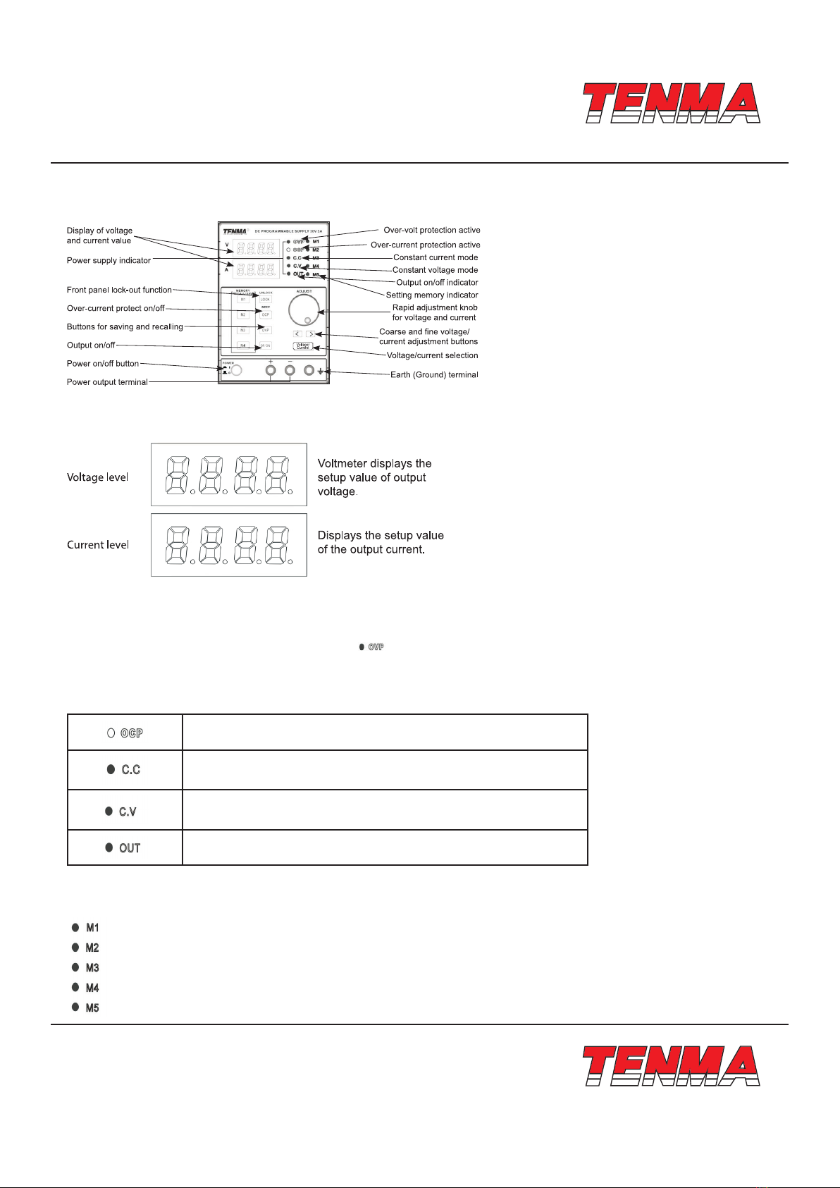
Output ON/OFF
Panel Operation
• The key LED will turn on once you have pressed the “output” key to turn output on.
• The key LED will then turn o once you have pressed the “output” key again to turn o output.
Note: If there are any of the following conditions, the output will automatically turn o:
• OVP means there is abnormal high voltage output or input on the output terminal.
• When OCP is on, the output current reaches the setting current value.
• Recalling other setups from the memory
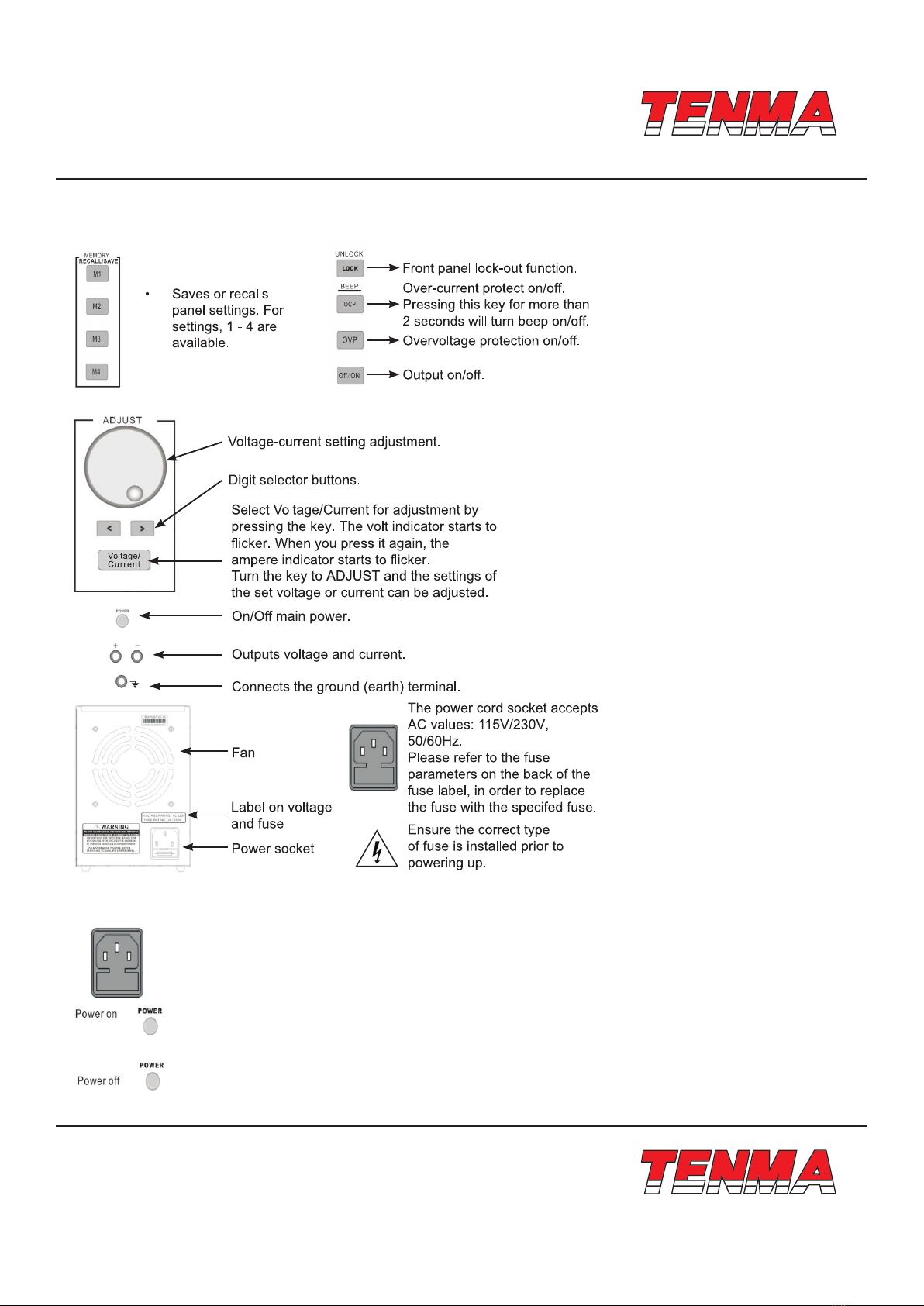
Beep ON/OFF
• By default, the beep sound is enabled.
• To turn o the beep, press the OCP (BEEP) key for two seconds.
• A beep sounds, meaning the beep setting will be turned o.
• To enable the beep, press the OCP (BEEP) key for two seconds again.
Front Panel Lock
Press the LOCK key to lock the front panel key operation. The key LED will turn on.
To unlock, press and hold the LOCK key for two seconds.
Output Setup
Panel Operation
• Connect the load to the front port, CH1 +/-.
• Press the Voltage/Current key to switch between the voltage adjustment and current adjustment. Adjust the voltage and
current with the Voltage/Current adjustment knob.
• By default, the voltage and current knob work in coarse mode. In order to activate in ne mode, press the key to choose
between coarse or ne mode.
• Turning on the output and pressing the output key will turn on the key LED and display CV or CC mode.
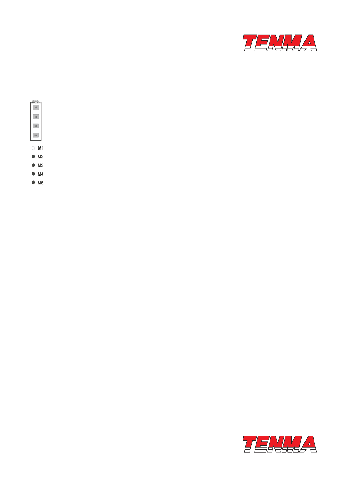
Save Setup
Background The front panel settings can be stored into one of the four internal
memories
Contents
The following list shows the setup contents:
• Fine/coarse knob editing mode
• Beep on/o
• Output voltage/current level
The following settings are always saved as “o”:
• Output on/o
• Front panel lock on/o
Panel Operation
Press one of the four buttons (M1, M2, M3, M4) and the LED light
turns on accordingly. After adjusting the value, it is automatically
saved, once the LED light stops blinking.