Conel CGU 04i User manual

GPRS modem CGU 04i
USER´S GUIDE
Declared system
ISO 9001:2009

CONTENTS
2
Contents
1. SAFETY INSTRUCTIONS......................................................................................................4
2. DESCRIPTION OF THE COMMUNICATION MODULE CGU 04I .........................................5
2.1. General ............................................................................................................................5
2.2. Examples of possible applications ...................................................................................5
2.3. Compatibility with other Conel company modems ...........................................................5
2.4. Description of CGU 04i components................................................................................6
2.4.1 GSM module...............................................................................................................6
2.4.2 Control microprocessor ..............................................................................................6
2.4.3 Telemetric inputs and outputs ....................................................................................7
2.4.4 Optional hardware interface PORT2 ..........................................................................7
2.4.5 User interface protocols..............................................................................................8
2.4.6 Sleep mode ................................................................................................................8
2.5. Technical parameters.......................................................................................................9
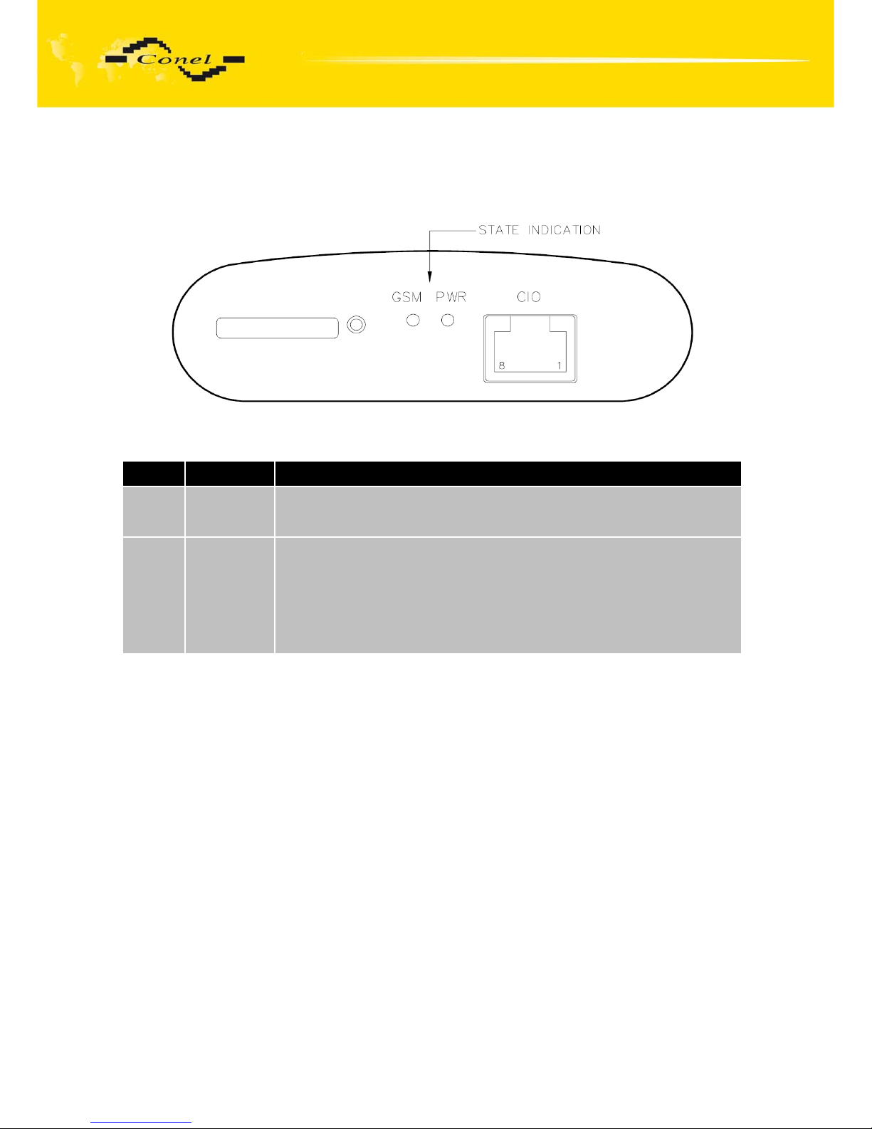
2.6. Module status indication.................................................................................................10
2.7. User interfaces (connectors)..........................................................................................11
2.7.1 PORT1 (PORT2) connector - RS232 .......................................................................12
2.7.2 PORT2 connectors...................................................................................................14
2.7.3 Connector PORT2 - RS485......................................................................................14
2.7.4 Connector PORT2 - RS422......................................................................................16
2.7.4.1 Connector PORT2 – MBUSD ................................................................................18
2.7.4.2 Connector PORT2 – CNT......................................................................................20
2.7.5 CIO connector ..........................................................................................................21
2.7.6 PWR supply connector.............................................................................................23
2.8. Antenna connection .......................................................................................................25
2.9. Technical specifications of port 2...................................................................................25
2.10. CGU 04i settings..........................................................................................................28
2.11. Service cable................................................................................................................28
2.12. Standard accessories...................................................................................................29
2.13. Additional accessories .................................................................................................29
2.14. Assembly procedure ....................................................................................................30
2.15. Mechanical external dimensions and mounting recommendations..............................32
2.16. Product marking...........................................................................................................35
2.17. PORT2 marking ...........................................................................................................35
2.18. CGU 04i production label.............................................................................................35
2.19. Expansion ports labels.................................................................................................36
2.20. Basic parameters description.......................................................................................37
3. QUALITY OF THE GPRS SIGNAL.......................................................................................42
3.1. Antenna installation for modems....................................................................................42
3.2. Good quality GPRS requirements:.................................................................................42
3.3. Example, station received these signals: .......................................................................42
3.4. Method of signal measurements....................................................................................43
3.5. AT^MONI command meaning........................................................................................43
3.6. AT^MONP command meaning ......................................................................................44
4. EXPANSION PORT MOUNTING .........................................................................................45
5. CIO – ANALOGUE INPUTS AND BINARY OUTPUTS ........................................................47
5.1. Description of I/O signal evaluation and reception.........................................................47

CONTENTS
3
5.1.1 Analogue input ......................................................................................................... 47
5.1.2 Binary output ............................................................................................................ 47
5.1.3 I/O signals inside CGU 04i ....................................................................................... 47
5.1.4 I/O signals parameters ............................................................................................. 48
5.2. Measuring other CGU 04i signals.................................................................................. 48
5.2.1 Measuring the supply voltage .................................................................................. 48
5.2.2 Measuring internal CGU 04i temperature ................................................................ 48
5.2.3 Measuring DSR output signal level .......................................................................... 49
5.3. Output signal for disconnection of supply voltage ......................................................... 49
5.4. Technical parameters .................................................................................................... 49
5.5. Connecting CIO signals to user device.......................................................................... 49
6. REFERENCES..................................................................................................................... 51
7. LINKS TO RELATED PRODUCTS OF THE MANUFACTURER......................................... 51
7.1. Systems ......................................................................................................................... 51
7.2. Protocols........................................................................................................................ 51
7.3. Software......................................................................................................................... 51
7.4. Products......................................................................................................................... 51
8. PRODUCT DISPOSAL INFORMATION .............................................................................. 52
9. COMPLAINTS PROCEDURE .............................................................................................. 53
10. WARRANTY....................................................................................................................... 55
Symbols used
Danger – important notice, which may have an influence on the user’s safety or the function
of the device.
Attention – notice on possible problems, which can arise to in specific cases.
Information, notice – information, which contains useful advices or special interest.
Conel s.r.o., Sokolska 71, 562 04 Usti nad Orlici, Czech Republic
Issue in CZ, 16/11/10

SAFETY INSTRUCTIONS
4
1. Safety instructions
Please observe the following safety instructions:
•The communication module must be used in compliance with all applicable international
and national laws and in compliance with any special restrictions regulating the utilization
of the communication module in prescribed applications and environments.
•Use only the original Conel company accessories. Thus you will prevent possible health
risks and damage to the devices and ensure compliance with all relevant provisions.
Unauthorised adjustments or use of unapproved accessories may result in damage to
the module and breach of applicable laws. Use of unapproved adjustments or accessories
may lead to cancellation of guarantee, which has no effects on your legal rights.
•The communication module CGU 04i must not be opened. Only the replacement of the
SIM card and expansion port is permitted.
•Caution! The SIM card could be swallowed by small children.
•Voltage at the feed connector of the communication module must not be exceeded.
•Do not expose the communication module to extreme conditions. Protect it from dust,
moisture and heat.
•It is recommended not to use the communication module at petrol stations. We remind
users to observe the limitations of radio devices use at pump stations, chemical plants or
where explosives are being used.
•Switch the communication module off in a plane. Use of the communication module may
endanger plane’s functions, interfere with mobile network and be illegal. By not following
these instructions the customer risks cancellation or termination of telephone services,
prosecution or both.
•You have to be extremely careful when using the communication module in proximity to
medical devices, such as pacemakers or hearing aids.
•Close to TV sets, radios and PCs the module may cause interference.
•It is recommended to create proper copy or backup of all the important settings saved in
the device’s memory, to database by help program Radwin, reference [3].

CGU 04i DESCRIPTION
5
2. Description of the communication module CGU 04i
2.1. General
GSM/GPRS communication module CGU 04i is a wireless data transmission device.
The communication module is one of the basic elements of AGNES GPRS system.
The system AGNES characteristics are described in reference [1]. GSM-GPRS infrastructure
is used for the wireless communication as a line layer. ARNEP protocol is implemented above
the line layer. The protocol ARNEP is described in reference [2]. On its basis the modules
create virtual private data network where data can be transferred between user devices via
any protocols.
One may simply imagine the CGU 04i module as a protocol converter between
the user device (PLC automatic, PC, data terminal, etc.) and GSM-GPRS infrastructure
of a mobile network operator, it provides the user with possibility to communicate simply
between all the systems. Apart from data transfers via GPRS the CGU 04i module enables
SMS.
The radio component GSM-GPRS is built in the CGU 04i module, consisting module
Cinterion.
GSM-GPRS module CGU 04i is controlled by communication 32-bit microprocessor.
It ensures GSM-GPRS communication, data transfer on serial user interfaces and a number
of diagnostic and service features. CGU 04i module in the basic version has one serial user
interface (communication port) RS232, one interface for direct connection of inputs
and outputs (CIO) for data collection and technological process management and one optional
user interface (RS232, RS422, RS485, M-BUSD, CNT). It is possible to set transfer
parameters and communication protocol for each user interface separately. As a result you
may communicate with various user interfaces using different communication protocols on
serial interface.
2.2. Examples of possible applications
•Security systems
•Telematics
•Telemetry
•Vending and dispenser machines
2.3. Compatibility with other Conel company modems
Regarding the communication and data transfers the CGU 04i module is compatible
with the older CGU 04 type (or CGU 02). This means it is possible to combine both types
in one network and simply extend an existing network of CGU 04 (CGU 02) modules
with new communication points using CGU 04i modules. CGU 04i provides some features not
included in the older CGU 04 type.
User and industrial communication protocol implemented on serial interfaces are
compatible with the protocols used for Conel radio modems (e.g. CDA 70). Thus you may
establish complex combined data networks consisting of both radio and GPRS modems.

CGU 04i DESCRIPTION
6
2.4. Description of CGU 04i components
2.4.1 GSM module
Cinterion module is used for GSM network wireless communication. It is integrated into
printed circuit board. FME antenna connector is accessible from the back panel. Release SIM
card reader is located on the front panel.
The MC39i module communicates in three GSM bands (900 MHz, 1800 MHz
and 1900 MHz). It can transmit in two „Time Slots“ and receive in four (GPRS multi-slot class
10 – maximum reception bit speed 85.6 kb/s). It supports CS-1, CS-2, CS-3 and CS-4
encryptions).
2.4.2 Control microprocessor
Thirty-two-bit microprocessor Freescale Coldfire with 64 kB SRAM backup memory,
512 kByte FLASH EEPROM memory and realtime circuit with reserve power supply makes
for the basis of CGU 04i control microprocessor. Software is based on realtime operating
system that processes simultaneous tasks. Thus parallel operation of all external interfaces
of the communication module is maintained.
The microprocessor is connected through serial interface to MC39i OEM module
and controls the communication via GSM-GPRS. Towards a user it is connected on serial
interfaces RS 232 (PORT1), and direct I/O signal processing circuits. The microprocessor
enables connection of up to two user devices through two interfaces. The second ports
are linked to RJ45 connectors marked PORT2. This interface may be RS232, RS422, RS485,
M-BUSD or CNT. All user interface signals are protected against overvoltage on the data
cable.
A device with different communication protocol can be connected to each interface.
The microprocessor may work as a protocol converter between separate serial user interfaces.
In case other than RS232 interface device needs to be connected, e.g. RS485/422,
it is possible to connect level converter to the serial port according to particular application.
The microprocessor can control such external converter.

CGU 04i DESCRIPTION
7
The microprocessor further manages numerous functions of servicing, diagnostic and
installation purposes. Data transfer statistics, separate port communications, power blackouts,
voltage of the reserve supply, CGU 04i temperature and other important information –
everything is recorded in the microprocessor’s memory.
CGU 04i settings are saved in FLASH EEPROM memory. Service SW RADWIN is
designed for CGU 04i module configuration. The description of programme RADWIN is
in reference [3].
2.4.3 Telemetric inputs and outputs
Apart from serial data interfaces there is CIO interface established in the module.
These are 5 signals to be used as analogue or binary inputs or binary outputs with an open
collector. The input is analogue 0 – 5 V. It may be as digital with control level adjustment.
The output is an open collector able to switch up to 500 mA. Reading and control of I/O signals
is possible from the remote CGU 04i module or any serial user interface. Simple technological
interface can be created by configuration of two CGU 04i modules, where you may control
remote outputs on the other module’s connector based on the input signals of one module.
Interface between CIO connector and technology is supplied for general use and it is
possible supplied this, providing voltage and current inputs of adjustable ranges, inputs for
resistance measuring (thermometers and the like), optically separated binary inputs and relay
outputs. With the equipment you may establish simple telemetry at low cost, without the using
of industrial control automates.
2.4.4 Optional hardware interface PORT2
PORT2 on the CGU 04i back panel provides for direct use of other HW interface than
the standard RS232. It is due to the design of the interface as a separate module built inside
CGU 04i. Thus you may use CGU 04i module combined with RS422, RS485, M-BUSD or
CNT. Such interface is physically linked to RJ45 PORT2 connector.

CGU 04i DESCRIPTION
8
2.4.5 User interface protocols
There are numerous industrial protocols implemented on the user interface:
•ARNEP UI
•PROFIBUS
•MBUS
•MODBUS
•AT modem
•SAUTER
•IWKA
•SBUS
•RADOM
•RDS CONEL
New protocols, not supported by the communication module yet, can be implemented
according to the customer’s needs. CGU 04i module also enables the implementation of own
user protocol directly by the customer.
In case of M-BUS expansion board installed and when chosen protocol is not M-BUS
or M-BUS TCP then sent data will be returned back to the device! If e.g. LINE protocol is set-
up on this port, then data will return back to the source.
2.4.6 Sleep mode
On mounting module CNT – PORT2 the CGU 04i module contains voltage supply
management. During idleness the module CGU 04i is switched to sleep mode, when energy
demand is very slow (100 μA). Time of switch to sleep mode is programme adjustable. Module
wake up it is possible of status change on port.

CGU 04i DESCRIPTION
9
2.5. Technical parameters
GSM module Cinterion
Complies with
standards
Power safety
EMC
Radio parameters
ČSNEN 60 950:2000
ČSN ETSI EN 301 489-1:V1.2.1; -7:V1.1.1
ČSN EN 55022
3GPP TS51.010-1,V5.5.0
ČSN ETSI EN 301 511,V7.0.1
Frequency bands EGSM900, GSM1800 and GSM1900 (GSM
Phase 2/2+)
Transmit power Class 4, 2 W for EGSM900
Class 1, 1 W for GSM1800
GPRS connection GPRS multi-slot class 10 (4+2)
GPRS mobile station class B
Communication speed Transmission
Reception
2 x Time slot (max. 42.8 kb/s)
4 x Time slot (max. 85.6 kb/s)
Temperature range Function
Storage
-20 oC to +55 oC
-40 oC to +85 oC
Supply voltage +10 to +30 V DC
Consumption GPRS TX
GPRS on-line
GSM stand-by
Sleep mode
3.5 W
1 W
350 mW
1 mW (on mounting module CNT – PORT2)
Dimensions 30 x 90 x 102 mm
(moulding fixed to DIN 35 mm slat)
Weight 150 g
Antenna connector FME – 50 Ohm
User interfaces PORT1
PORT2
CIO
RS232 - connector RJ45 (300 b/s - 115 200 b/s)
Optional - connector RJ45 (300 b/s - 115 200
b/s) RS232, RS422, RS485, M-BUSD, CNT – (2
counters, 2 binary inputs, 2 analogy inputs, 1
binary output - open collector)
5 SW adjustable inputs (analogue, binary) /
outputs (open collector) – RJ45 connector

CGU 04i DESCRIPTION
10
2.6. Module status indication
There are two LED indicators on the front panel informing on its status.
Colour Description Description
GREEN PWR
Flashes once a sec………..….proper function
Lights permanently……….…...fault
Off…………………………...….no DC supply or sleep mode
RED GPRS
Lights permanently…………...neither serial established
Flashes rapidly……………......serial connection being established,
Flashes slowly………….……..serial connection established
Flashes together with PWR….station activation failed
Inverse flashing to PWR……..no DNS connection
Off………………………….......GSM GPRS communication established
Flashes dimly…………….…...GPRS transmission or reception
zSerial connection – Establishment connection in face of GSM network at the level AT
commands.
zStation activation – Modem authentication in global DNS, reference [1].
zDNS connection – Establishment connection with distributed database for interface
address translation to IP address.
zGPRS – General Packet Radio Services is transfer technology, which it work on co-
called „transfer data packet“, when the GPRS simply make use of free space
(space=slot) in GSM network.

CGU 04i DESCRIPTION
11
2.7. User interfaces (connectors)
There are RJ45 (PORT1 and PORT2), RJ12 (PWR) and FME (ANT) connectors
located on the back panel. The two PORT1 and PORT2 (optional) connectors are for user
interfaces. The fourth PWR connector is for supply adapter connection. Antenna is connected
to the last, ANT connector.
There is RJ45 (CIO) connector located on the front panel. The CIO connector is for direct input
and output connections for data collection and technology control.

CGU 04i DESCRIPTION
12
2.7.1 PORT1 (PORT2) connector - RS232
Panel socket RJ45 (RS232 – DCE - Data Communication Equipment).
Pin
number Signal
mark Description Data flow
direction
1 RTS Request To Send Input
2 CTS Clear To Send Output
3 DTR Data Terminal Ready Input
4 DSR Data Set Ready – connected to +4 V through 330 Ohm Output
5 GND GROUND – signal ground
6 RXD Receive Data Output
7 CD Carrier Detect Output
8 TXD Transmit Data Input
Example of the meter connection to the CGU 04i:
Meter
Pin 1
–
RTS
Pin 2 – CTS
Pin 3 – DTR
Pin 4 – DSR
Pin 5 – GND
Pin 6 – RXD
Pin 7 – CD
Pin 8 – TXD
Modem CGU 04i
GND
RXD
TXD

CGU 04i DESCRIPTION
13
Example of the PC connection to the CGU 04i:
zCable KD2 is connected to serial port PC (example COM1)
Example of the RS232 equipment connection to the CGU 04i (possibility to use all RS232
ports):
Cable KD-2
Modem CGU 04i
PORT1
PORT2
PWR
Cable KD-2 Modem CGU 04i
PORT1
PORT2
PWR

CGU 04i DESCRIPTION
14
2.7.2 PORT2 connectors
On demand of the client it is possible mounting second interface. The second interface
may be RS232, RS422, RS485, M-BUSD or CNT. If PORT2 isn't mounted, connector will not
active.
2.7.3 Connector PORT2 - RS485
Panel socket RJ45
Pin
number Signal
mark Description Direction
1 GND Signal and supply ground
2 GND Signal and supply ground
3 TxRx- RS485 B (-) Input/Output
4 TxRx+ RS485 A (+) Input/Output
5 TxRx- RS485 B (-) Input/Output
6 TxRx+ RS485 A (+) Input/Output
7 +12V EXT External supply
8 +12V EXT External supply
BEWARE! Power supply is selected on module PORT2-RS485 by help jumper, ref. 2.9.

CGU 04i DESCRIPTION
15
Circuit example of the equipment with a modem with data length less than 10 m:
Circuit example of the equipment with a modem with data length more than 10 m:
At RS485 data cable more than 10m it is need to use overvoltage protection on the
modem side!
Pin 1
–
SGDN
Pin 2 – SGND
Pin 3 – RS485 (-)
Pin 4 – RS485 (+)
Pin 5 – RS485 (-)
Pin 6 – RS485 (+)
Pin 7 – +12V EXT
Pin 8 – +12V EXT
Modem CGU 4i
SGND
RS485 (-)
RS485 (+)
Meter
SGND
RS485 (-)
RS485 (+)
Meter DC +
Pin 1
–
SGND
Pin 2 – SGND
Pin 3 – RS485 (-)
Pin 4 – RS485 (+)
Pin 5 – RS485 (-)
Pin 6 – RS485 (+)
Pin 7 – +12V EXT
Pin 8 – +12V EXT
Modem
CGU 04i
SGND
RS485 (-)
RS485 (+)
Meter
SGND
RS485 (-)
RS485 (+)
Meter
1X
2X
1Y
2Y
OVPM-
21
DC +

CGU 04i DESCRIPTION
16
2.7.4 Connector PORT2 - RS422
Pin
Number Signal
mark Description Data direction
1 GND Signal and supply ground
2 GND Signal and supply ground
3 RxD- Receive Data (-) Input/Output
4 RxD+ Receive Data (+) Input/Output
5 TxD- Transmit Data (-) Input/Output
6 TxD+ Transmit Data (+) Input/Output
7 +12V EXT External supply
8 +12V EXT External supply
ATTENTION! Power supply is selected on the expansion port RS422 by help of a
jumper, ref. 2.9. If galvanic separation is required the converter must have an external
power supply.
Circuit example of the equipment with modem with data length less than 10 m:
DC
Meter
SGND
TxD(-)
TxD(+)
RxD(-)
RxD(+)
Modem CGU 04i
Pin 1
–
SGND
Pin 2 – SGND
Pin 3 – RxD (-)
Pin 4 – RxD (+)
Pin 5 – TxD (-)
Pin 6 – TxD (+)
Pin 7 – +12V EXT
Pin 8 – +12V EXT
+

CGU 04i DESCRIPTION
17
Circuit example of the equipment with a modem with data length more than 10 m:
At RS422 data cable more than 10m it is need to use overvoltage protection on the
modem side!
1Y
2Y
DC
Meter
SGND
TxD (-)
TxD (+)
RxD (-)
RxD (+)
Modem
CGU 04i
Pin 1
–
SGND
Pin 2 – SGND
Pin 3 – RxD (-)
Pin 4 – RxD (+)
Pin 5 – TxD (-)
Pin 6 – TxD (+)
Pin 7 – +12V EXT
Pin 8 – +12V EXT
+
1X
2X
OVPM-31
1X
2X
1Y
2Y

CGU 04i DESCRIPTION
18
2.7.4.1 Connector PORT2 – MBUSD
Panel socket RJ45
Pin
number Signal
mark Description Direction
1 SGND Signal and supply ground
2 SGND Signal and supply ground
3 TxRx- MBUS B (-) Input/Output
4 TxRx+ MBUS A (+) Input/Output
5 TxRx- MBUS B (-) Input/Output
6 TxRx+ MBUS A (+) Input/Output
7 +12V EXT External supply
8 +12V EXT External supply
BEWARE! External supply is for converter MBUSD!
If galvanic separation is required the converter must have external power supply.
Circuit example of the equipment with a modem with data length less than 10 m:
DC
Meter SGND
MBUS (-)
MBUS (+)
Meter
SGND
MBUS (-)
MBUS (+)
Modem CGU 04i
Pin 1
–
SGND
Pin 2 – SGND
Pin 3 – MBUS (-)
Pin 4 – MBUS (+)
Pin 5 – MBUS (-)
Pin 6 – MBUS (+)
Pin 7 – +12V EXT
Pin 8 – +12V EXT
+

CGU 04i DESCRIPTION
19
Circuit example of the equipment with a modem with data length more than 10 m:
If an M-BUS data cable more than 10m it is need to use overvoltage protection on the
router side!
DC
Meter SGND
MBUS (-)
MBUS (+)
Meter
SGND
MBUS (-)
MBUS (+)
Modem
CGU 04i
Pin 1
–
SGND
Pin 2 – SGND
Pin 3 – MBUS (-)
Pin 4 – MBUS (+)
Pin 5 – MBUS (-)
Pin 6 – MBUS (+)
Pin 7 – +12V EXT
Pin 8 – +12V EXT
+
1X
2X
1Y
2Y
OVPM-21

CGU 04i DESCRIPTION
20
2.7.4.2 Connector PORT2 – CNT
Panel socket RJ45
Pin
number Signal
mark Description Direction
1 BIN0/CNT0 Binary input/counter input Input
2 BIN1/CNT1 Binary input/counter input Input
3 BIN2 Binary input Input
4 BIN3 Binary input Input
5 GND Signal ground
6 OUT0 Binary output Output
7 AN0 Analogy input Input
8 AN1 Analogy input Input
Typical connection of CGU 04i measuring circuits
Table of contents
Other Conel Modem manuals