Conextion sonoma ten Service manual

Owner’s and
Installation Manual
sonoma™ Series
Indoor/Outdoor Speakers
Includes Models
sonoma™ ten and twenty

sonoma™ Series Indoor/Outdoor Speakers
2
Owner’s and Installation Manual
3
Introduction
Congratulations and thank you for choosing a
sonoma™ Series Loudspeaker from coNEXTion
Systems! With proper installation and operation,
you’ll enjoy years of trouble-free use either indoors
or out. We work very hard to ensure that all of
our speakers consistently deliver exceptional
performance and value. We hope you enjoy
them to their fullest. Please take a moment to
read this manual so that you can get the most
from your new speakers. coNEXTion Systems
manufactures a full line of ceiling, inwall, and
indoor/outdoor speakers. To learn more about our
products, and to see a video demonstration of the
sonoma™ Series speakers, please visit our web
site at www.conextionsystems.com or call us at
866-310-NEXT (6398). Use the illustrations below
to familiarize yourself with the major components
of your new sonoma™ Series Loudspeaker.
Major Components of the
sonoma™ ten Speaker
Major Components of the
sonoma™ twenty Speaker Dual Voice Coil
5.25" Aluminum Woofer
SFPC™ Passive Radiator
1" Aluminum Tweeters
End Cap
Angle Locking Lever
Speaker Terminals
All-in-one
Mounting Bracket
sonoma™ 20
Speaker Enclosure
5.25" Aluminum Woofer
SFPC™ Passive Radiator
1" Aluminum Tweeter
End Cap
Angle Locking Lever
Speaker Terminals
All-in-one
Mounting Bracket
sonoma™ 10
Speaker Enclosure

sonoma™ Series Indoor/Outdoor Speakers
2
Owner’s and Installation Manual
3
Features and
Benets
sonoma™ ten—Two-way Speaker
sonoma™ ten speakers feature a single aluminum
5.25" woofer and a single 1" aluminum tweeter
for each channel in a traditional stereo pair design.
sonoma™ twenty—
Single Point Stereo Speaker
When you need a stereo image, but only have
room for one speaker, the sonoma™ twenty will
do the job! The twenty features a dual voice coil
aluminum 5.25" woofer and two 1" aluminum
tweeters mounted at a 45° angle that reproduces
a stereo image out of a single enclosure.
sonoma™ Speakers Sound Better and
Install Faster
Our entire line of sonoma™ Series speakers fea-
ture a sleek architectural design that easily blends
into all installation environments. The all-in-one
speaker and installation bracket design is ready to
install right out of the box. No more disassemble
and reassemble issues with a two piece bracket
and trying to thread the mounting knobs while
holding a speaker and standing on a ladder!
Stealth Designed “End Caps”—
the Secret Hideaway
The sonoma™ unique “end cap” design hides the
four pre-threaded mounting screws, the speaker
terminals and wire, and the locking lever (see be-
low) for a more theft-resistant installation.
Aiming and Locking the Angle
Your speaker has the ability to adjust (lock and un-
lock) the angle of the speakers with a convenient
and easy-to-use lever system providing up to 40°
of adjustment to the optimal listening position.
The World’s First Indoor/Outdoor SFPC™
Weather-resistant Bass Extension System
All sonoma™ Series speakers feature our SFPC
(side ring pneumatic coupled) design. The SFPC
system features dual passive radiators molded into
the speaker cabinet. Working in concert with the
5.25" aluminum driver, the SPFC radiators provide
exceptional bass response from a small volume
cabinet, and when used outdoors, eliminate any
risk of moisture damage to the speakers.
No Compromise Water-resistant
Construction
The sonoma™ Series cabinets are made out of
state-of-the-art glass-lled structural 6/6 nylon,
with a cabinet thickness that is much more ro-
bust than other products. This provides the best
“acoustically inert” design on the market to-
day, with “MDF” like performance in a weather-
resistant cabinet, and allows us to use mechanical
designs that enhance the overall acoustic perfor-
mance and eliminates any chance of mechanical
buzz and rattle.
A weather-resistant powder-coated aluminum
grille is utilized to eliminate the possibility of corro-
sion typically found with standard steel.
Alternate Mounting Options
In addition to the all-in-one bracket, the sonoma™
Series may be mounted using the two rear mount-
ed 1/4-20 inserts that enable the use of custom
mounting brackets for alternative angles or depths
that may be desired. Table top speaker stands are
included for alternate installation places both in-
door and outdoor.

sonoma™ Series Indoor/Outdoor Speakers
4
Owner’s and Installation Manual
5
Convenient Five
Step Mounting
Instructions
Installation of your new sonoma™ Series Speakers
involves ve easy steps:
1. Choose a location
2. Open the “end-caps”
3. Wire the speaker
4. Level the speaker
5. Drive the screws
6. Angle the speakers (optional)
Speaker Location Suggestions
The sonoma™ ten speakers may be located any-
where within the listening area. Placing any speak-
er in close proximity to other boundary surfaces
will add more bass sound effect. Placing the speak-
er away from “boundaries” will create less bass. In
addition, the more directly on axis to the speaker
you are, the more high frequency information you
will hear. When using two speakers to reproduce
stereo, determine the area where most listeners
will be, then try to locate the speakers where the
listeners will get a reasonable balance of sound
from both speakers.
A stereo pair of speakers should be placed at the
front of the listening area, and half the distance
apart from the distance to the seating area if pos-
sible. This provides the best stereo imaging. For ex-
ample, if the seating to the speakers is 8 feet, the
speakers should be 4 feet apart. See Figure 1.
When using the sonoma™ twenty, single point
stereo speaker, try to pick a place that will have
the best overall coverage of the listening area. See
Figure 2.
If you have a large listening area, we recommend
using multiple sonoma™ twenty speakers so that
all areas will have a stereo image. See Figure 3.
Figure 1 Suggested sonoma™ 10 speaker placement for
best stereo imaging.
Listening areasonoma™ 10 speakers
Figure 2 Suggested speaker placement for average
listening area using single sonoma™ 20 speaker.
Listening areasonoma™ 20 speaker
Figure 3 Suggested speaker placement for large listening
area using multiple sonoma™ 20 speakers.
Listening areasonoma™ 20 speakers

sonoma™ Series Indoor/Outdoor Speakers
4
Owner’s and Installation Manual
5
Installation Is Easy…
Just Open the End-caps
The sonoma™ Series mounting system has been
designed for a quick and easy installation. Remove
the speaker from the carton. Hold the speaker hor-
izontally, and open the “end-caps” on both sides
of the speaker. You will see that there are two
pre-threaded stainless steel #8 x 2" Phillips head
screws on each side, for a total of four mounting
screws. We have also included (4) 8 x 3” stainless
steel Phillips head screws for times when you may
need additional length.
NOTE: For vertical mounting, there is an
alternate center hole in between the pre-
mounted screw holes that should be lined up
with a stud if possible. In the vertical orienta-
tion, only two screws may be used.
Thread the speaker wire through the hole (see
Figure 4). We have provided a wire channel in the
back of the speaker to allow the wires to be hid-
den from view.
Speaker Wire and Connections
We recommend that you connect your speakers
using high quality 16 gauge stranded wire. For
wiring runs longer than 80 feet, we recommend
14 gauge stranded wire. Remove 1/2" of insu-
lation from the end of each input speaker wire.
Open the end caps. Depending on the orientation
of the speaker, on one end there will be speaker
terminals and a hole for the speaker wire (s) to
be threaded through. Push down on the terminal
connector and a large opening will appear in the
shaft of the connector that is capable of holding
up to 10 gauge wire. Insert the bare wire into the
opening and release the terminal.
Be sure to observe correct polarity, connecting the
positive (+) leads to the red terminals and the nega-
tive (-) leads to the black terminals. Also, be sure that
no stray strands of wire touch across the terminals.
NOTE: For the single point stereo sonoma™
twenty, there are two pairs of speaker termi-
nals, for both positive and negative of both
left and right channels.
Figure 5 Speaker Terminal
Figure 4 Rear View of sonoma™ Series Speaker (sonoma™ ten shown).
Mounting
Screw Holes
Mounting
Screw Holes
Speaker
Wire Hole
Wire Chase

sonoma™ Series Indoor/Outdoor Speakers
6
Owner’s and Installation Manual
7
Level the Speaker and Drive the Screws
After the wires are in the channel, be sure that the
speaker is level and then tighten the mounting
screws on both sides of the speaker into the mount-
ing surface behind the speaker. To avoid stripping
the screws, it may be necessary to drill pilot holes
before you begin to tighten the screws. For your ref-
erence, the mounting hole dimensions are 14.65"
center to center, and the distance between each
mounting hole under the end-caps is 2".
IMPORTANT NOTE: coNEXTion Systems is
not responsible for the stability or instability
of your speaker installation. The sonoma™
Series speakers weigh between 8 and 10 lbs.
Depending on what material you are mount-
ing the speaker to, you and/or your install-
er will need to assess if the installation will
need additional “anchors”, etc. to hold the
weight. In the vertical orientation, mounting
to a stud is preferable.
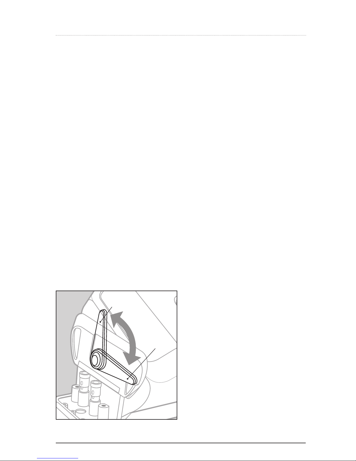
Adjusting the Angle of the Speaker
After you have installed the speaker, you can ad-
just the angle of the tilt, up to 40 degrees, to ob-
tain a more directional setting to the listening area.
It is not necessary to angle the speaker earlier in
the installation. Open the end caps, and locate the
levers on each side. Unlock the lever by turning it
so that the lever faces in towards the speaker. Both
levers MUST be unlocked. Then carefully grip the
cabinet and adjust the tilt up or down in the hor-
izontal orientation, or left to right in the vertical
orientation. When you have reached your desired
angle, move the levers back to their original posi-
tion. Be sure to lock both levers.
NOTE: Do not try to adjust the angle while
the levers are in the locked position, as this
may damage the mechanism.
A Note on the Grille
Please use care when removing and reinstalling the
grille on to the speaker. On the long sides of the
speaker, you will notice that there are catch chan-
nels for the grille. It is important to make sure that
the grille catches these at the same time that the
“ends” of the grille are snapped in.
The grille and the speaker should be cleaned with
a dampened soft cloth.
A Note on Painting the
Speaker and the Grille
The speaker may be left as is or painted to match
your décor. If you need to paint the speaker, be
sure to “mask-off” the driver, the passive radia-
tors, tweeter(s), and speaker connectors, so that
the paint does not come in contact with these
components. If you need to paint the grille, re-
move it from the speaker rst. Spray painting (us-
ing slightly thinned paint) is the best method to
paint the grille. If you paint the grille, use air pres-
sure to “blow out” any grille holes that become
covered over with paint. Be sure to use paint that is
labeled safe for plastics. Many spray paints intend-
ed for use on wood or metal contain solvents that
may damage the speaker assembly. Also, do not
attempt to clean any plastic parts of the speakers
with solvents or any petroleum based products.
Figure 6
One of the Angle Levers at each end of the Speaker.
Unlocked
Position
Locked
Position

sonoma™ Series Indoor/Outdoor Speakers
6
Owner’s and Installation Manual
7
Specications
All sonoma™ Series speakers feature: All-in-one speaker and bracket design with a 40 degree tilt angle;
SFPC weather-resistant bass extension system; and molded glass-lled structural nylon 6/6 for acousti-
cally inert cabinets.
Model sonoma™ ten sonoma™ twenty (Single Point Stereo)
Drivers Woofer 5.25" Aluminum with butyl rubber
surround
5.25" Aluminum with butyl rubber
surround with Dual Voice Coil
Tweeter 1" Aluminum 2 (two) - 1" Aluminum mounted at a
45° angle
Recommended Amplier Power 10 to 300 wpc 10 to 300 wpc
Modes Mono Single Point Stereo
Nominal Impedance 4ohm 8ohm/channel
Frequency Response 60Hz to 20kHz, +/- 3dB 60Hz to 20kHz, +/- 3dB
Sensitivity 89dB 89dB
Overall Exterior Dimensions (L x W x D) 15.35" x 6.90" x 7.03" 15.35" x 6.90" x 7.03"
Weight (ea.) 10 lbs 10 lbs
Packaging 2 per box 1 per box
coNEXTion Systems, Inc.
5105 E. Los Angeles Avenue #132
Simi Valley, CA 93063
www.conextionsystems.com
866.310.NEXT (6398)
©2004 coNEXTion Systems, Inc. All Rights Reserved. coNEXTion Systems, the coNEXTion logo, sonoma™, and SFPC are trade-
marks of coNEXTion Systems, Inc. All specications are subject to change without notice.

Part No. 300200-8915
This manual suits for next models
1
Table of contents
Other Conextion Speakers manuals