zc Series Ceiling Speakers 2
Owner’s and Installation Manual 3
Features and
Benets
zc Series Speakers
Sound Better and Install Faster
All our zc Series Speakers feature Z-Tool™ and SnapLok™
Installation…That’s Right—NO TOOLS!
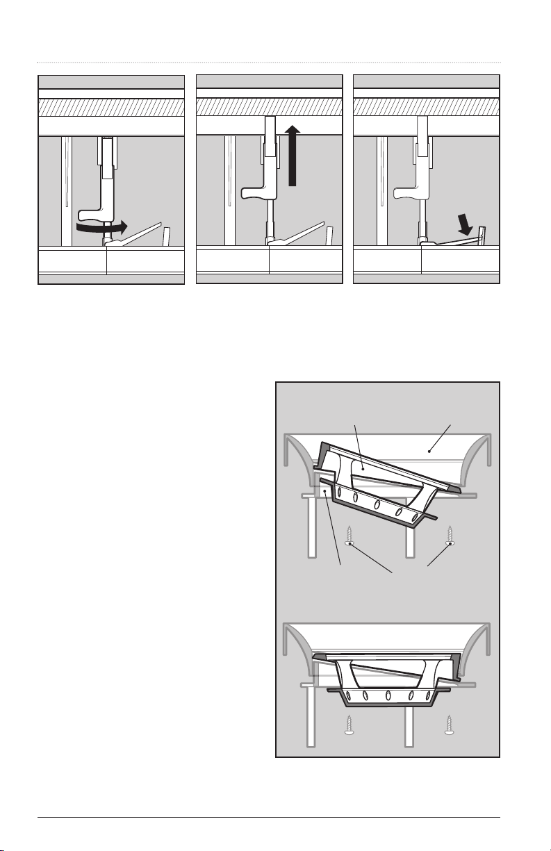
Our patent-pending Z-Tool™ system for zero tool in-
stallation allows the frame to be mounted in the ceil-
ing without the use of any tools! Our unique, proprietary
mounting mechanism allows the installer to secure the
speaker frame rmly against the drywall in seconds.
We also created the patent-pending SnapLok™ angled
(up to 20°) bafe that drops into place, requiring no pre-
alignment. A simple hook mechanism snaps the bafe into
place. This method is safer, quicker and easier than any oth-
er ceiling speaker installation system on the market today.
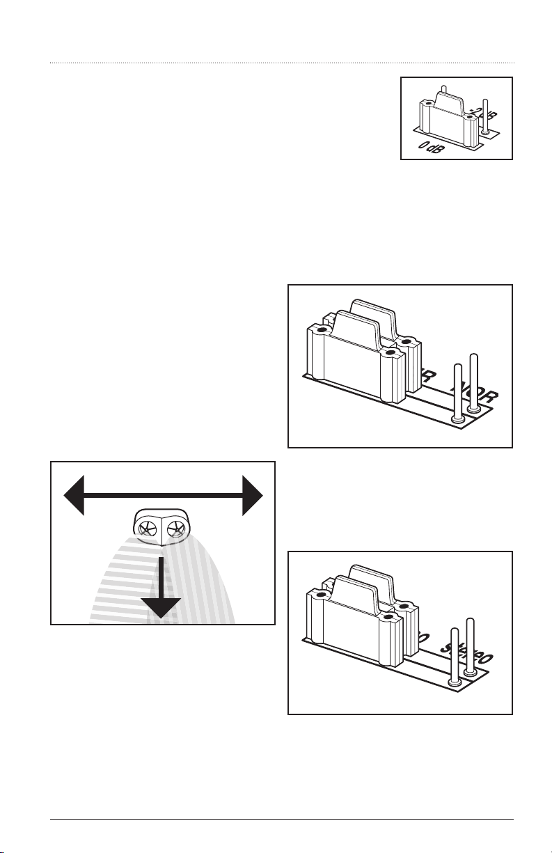
50° No Diffraction Angling Tweeter
All zc Series models feature a 50° (that’s 3.5 times more
than traditional tweeters) no diffraction angling (pivoting
ball) tweeter that enables it to be pointed towards the
listening position, and be locked into position (except the
z200c, which has a 20° no diffraction angling tweeter).
On the three-way z500c and z600c the midrange is also
part of this angling assembly.
The Direct Axis Extending Tweeter™
The patent-pending Direct Axis Extending Tweeter™
not only maintains the 50° rotation, it can extend ap-
proximately 1" below the ceiling and actually be pointed
toward the listening position. When combined with the
20° angling woofer, up to 70° of acoustic focusing con-
trol is available. However, for times when aesthetics rule
over acoustics, the tweeter can be retracted to a traditional
ush setting. This feature is available on all models except
the z100c and z200c.
No Compromise Construction
We use state-of-the-art parts and materials (glass-lled
structural 6/6 nylon), with section thicknesses much more
robust than other products. This allows us to use me-
chanical designs that enhance the overall acoustic perfor-
mance with no chance of mechanical buzz or rattle.
Acoustic Controls
Bass and treble can be ne tuned to accommodate re-
ective surfaces, corner loading, and personal tastes.
Adjustment is accomplished via the bafe-mounted
treble control (-2dB, 0dB and +2dB) and circuit board
mounted bass jumper (0dB, -1dB, and -2dB).
Selectable Impedance
Speaker impedance can be set depending on your sys-
tem needs—4 ohms where maximum current transfer
and output level is desired; 8 ohms for systems utilizing
multiple speaker pairs where amplier loading is a con-
sideration. (Available on all models except z200c.)
FlexSpeak™: Three Speakers In One!
The FlexSpeak™ dual tweeter and voice coil speaker can
be wired as a single channel of a stereo pair, a single
point stereo speaker, or as a D2 directDiffuser™ for use
as a surround speaker. (Available on Model z200c only.)
See page 9 for details.
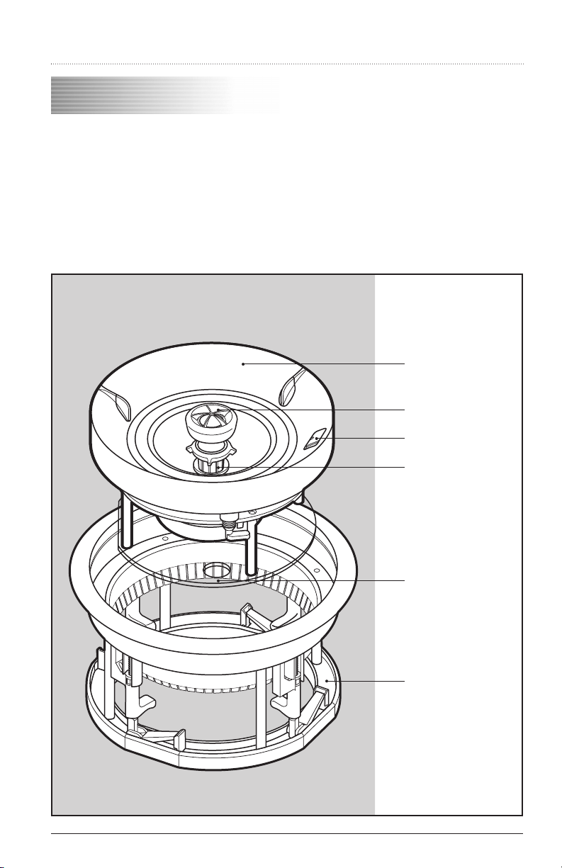
Carton Contents
All zc Series models have been conveniently packaged to
coincide with your installation schedule. The sheetrock
cutout template, the Z-Tool™ frame and the contoured
grille (where applicable) are located at the top of the car-
ton. The speaker bafe is located underneath, so that it
can be stored in a safe place until you are ready to install
the rest of the product. We have also included a ush
grille at the bottom of the carton. The z100c and z200c
are shipped with the ush grille only.
This system has been designed so that a “paint shield” is
unnecessary, as any painting should be done before the
actual speaker bafe is installed.
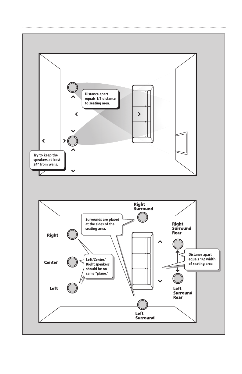
Speaker Placement
Suggestions
For general operation, the zc Series speakers can be lo-
cated anywhere within the listening area. As a rule, it
is best to keep them at least 24 inches away from any
wall boundaries (ceiling/wall/corner). Placing any speak-
er in close proximity to a boundary surface will always
“color” the sound that the speaker produces. Even with
frequency adjustments, only small improvements can
be made to the detrimental effects of boundary reec-
tions. In addition, the more directly under the speaker
you are, the more high frequency information you will
hear. When using two speakers to reproduce stereo, con-
sider where the majority of the room’s occupants will be
most of the time. Then try to locate the speakers where
the listeners will get a reasonable balance of sound from
both speakers.