CONFLOW Power Genex IPGIPC315 Manual

M/IPC/I/E
04 2016
Manuale di installazione e manutenzione
Installation and maintenance manual
Convertitore elettropneumatico digitale
Digital electropneumatic converter
Power Genex
®
Servizio Assistenza - Servicing Department
Via Lecco, 69/71
20864 AGRATE BRIANZA (MB) – ITALY
Tel. - Phone : +39 - (0)39 - 651705 / 650397
Fax : +39 - (0)39 – 654018
Web: www.conflow.it

INDICE
Pag.
INDEX
Page
1
DESCRIZIONE
1
1
DESCRIPTION
1
2
DATI TECNICI – Tipo IPC
1
2
TECHNICAL DATA – Type IPC
1
3
INFORMAZIONI GENERALI DI
SICUREZZA
1
3
GENERAL AND SAFETY INFORMATION
1
4
INSTALLAZIONE
1
4
INSTALLATION
1
4.1
Connessioni pneumatiche
1
4.1
Pneumatic connections
1
4.2
Connessioni elettriche
2
4.2
Electric connections
2
5 AVVIAMENTO 2 5 START-UP 2
6 CORREZIONE DELLO ZERO 2 6 ZERO SETTING 2
7 CORREZIONE DEL CAMPO 2 7 SPAN SETTING 2
8 REGOLAZIONE DEL DUMPING (pendolamento) 2 8 DUMPING SETTING (hutting) 2
9 MANUTENZIONE 2 9 MAINTENANCE 2
10 DICHIARAZIONE DI CONFORMITA’ Vedi
sotto
10 DECLARATION OF CONFORMITY See
below
A. Descrizione / Description:
Convertitore Elettropneumatico Digitale Tipo IPC…
Digital Electropneumatic Converter IPC… Type
Tipo IPC015 – IPC018 – IPC315 – IPC630
Type IPC015 – IPC018 – IPC315 – IPC630
Numeri di matricola / Serial Numbers: vari - various
riportato sulla targhetta identificatrice/ marked on identification plate
B. Norme armonizzate applicate / Applicable Harmonized Standards :
EN 50082-1 : 1998
EN 55011 : 1999
EN 61010-1 1993 including AMD2 : 1995
CERTIFICATO DI CONFORMITA’. I prodotti sono stati verificati e ispezionati rispetto al nostro Sistema Controllo Qualita' UNI EN
ISO 9001. Noi certifichiamo che questo prodotto corrisponde alla Vostra richiesta e che le sue caratteristiche sono in
conformita' con le nostre specifiche tecniche.
CERTIFICATE OF CONFORMITY This product has been manufactured, tested and inspected in accordance with our Quality Assurance
System UNI EN ISO 9001. We certify that it contents correspond to the order placed and its performance is in conformance with our
technical specifications.
Date of Issue / Data di rilascio
25/02/2013
DICHIARAZIONE DI CONFORMITA’ ALLA DIRETTIVA EUROPEA N° 89/336/EEC
Declaration of conformity according to DIRECTIVE N° 89/336/EEC

1 – DESCRIZIONE
1 – DESCRIPTION
Il convertitore IPC è utilizzato per la trasformazione di un
segnale in corrente continua in un segnale pneumatico.
Il convertitore IPC è provvisto di una valvola piezoelettrica ad
alta velocità con possibilità di azzerare il segnale in uscita
per un corretto controllo di valvole di regolazione senza
posizionatore pilota.
IPC converter is employed for conversion of a standard DC
current signal into a standard pneumatic signal.
IPC converter is provided of high speed piezoelectric valve with
the possibility to obtain zero output signal
for a correct
control of pneumatic control valves without pilot positioner.
2- DATI TECNICI tipo IPC :
2- TECHINICAL DATA type IPC :
Connessioni pneum. IN-OUT
1/8 “ NPT
IN-OUT pneum. Connections
1/8 “ NPT
Connessione elettrica
PG9
Electric connection
PG9
Montaggio Su canalina 35 mm DIN EN 50022 Mounting
On 35 mm Rail according to
DIN EN 50022
Grado di protezione
IP 55
Protection
IP 55
Ingresso
4 – 20 mA
Input
4 – 20 mA
Tensione
≤
36 V
D.C. Voltage
≤
36 V
Corrente continua
≤
100 mA
D.C. Current
≤
100 mA
Consumo energia
≤0,50 W
Power consumption
≤0,50 W
Linearità – Isteresi – ripetibilità
+ / - 0,3 % del campo
Linearity – Hysteresis – repeat.
+ / - 0,3 % of span
Impedenza
425
Ω
a 20 mA
Impedance
425
Ω
at 20 mA
Campi disponibili standard
0 – 15 psi … 0 –1 bar
Standard range
0 – 15 psi … 0 –1 bar
0 – 18 psi … 0 –1,2 bar
3 – 15 psi … 0,2 – 1 bar
6 – 30 psi … 0,4 – 1,2 bar 6 – 30 psi … 0,4 – 1,2 bar
Campi configurabili
A scelta
es. 3-9 psi o 9-12 psi o 10-20 psi Configurable range
On Your Own choice
i.e. 3-9 psi .. 9-12 psi ..10-20 psi
Massima pressione operativa
1,4 - 6 bar
Max Operating pressure
1,4 - 6 bar
Temperatura Ambiente
-20 °C … + 70 °C
Operating temperature range
-20 °C … + 70 °C
Peso
0,88 Kg
Weight
0,88 Kg
3 – INFORMAZIONI GENERALI DI SICUREZZA
3 – GENERAL AND SAFETY INFORMATIONS
Prima di installare gli apparecchi rimuovere le protezioni di
plastica poste a copertura degli attacchi di connessione.
Before installing positioner, remove plastic covers placed on
connection ends.
ATTENZIONE
Durante il funzionamento gli
apparecchi contengono pressione d’aria.
WARNING
Be careful during functioning the
positioners are under air pressure.
ATTENZIONE Prima di iniziare eventuali
operazioni di manutenzione assicurarsi che il
convertitore non sia in pressione .
WARNING Before starting maintenance be sure
that the converter is not pressurized .
ATTENZIONE Non rimuovere mai la scheda
elettronica e conseguentemente la valvola
pilota tarata in fabbrica.
WARNING Never remove the electronic card
and the pilot valve setted in the factory.
La mancata osservanza delle informazioni generali di
sicurezza, delle norme vigenti e delle istruzioni di montaggio
possono:
•Causare pericolo per l’incolumità di chi sta eseguendo le
manovre o di terzi
•Co
mpromettere l’efficiente funzionamento del
convertitore
In the event of non-observance of the general rules, safety
informations and of the installation instructions, this may:
•Cause danger to life and limb of the user or third party
•Endanger the efficient functioning of the converter
4 – INSTALLAZIONE
4 – INSTALLATION
L’installazione è universale ma si consiglia di installare il
convertitore in posizione verticale, con la connessione elettrica
verso l’alto.
Fissare il convertitore ad una canalina DIN EN 50022 35 mm.
Agganciare il convertitore alla guida ed eseguire i collegamenti
come indicato al punto 4.1 e 4.2
The installation is universal but is suggested a vertical
installation, with the electrical connection on the upper side.
Fix the converter on a DIN EN 50022 mounting rail (lenght 35
mm).
Grapple the converter to the mounting rail and connect it, as
shown in the point 4.1 and 4.2
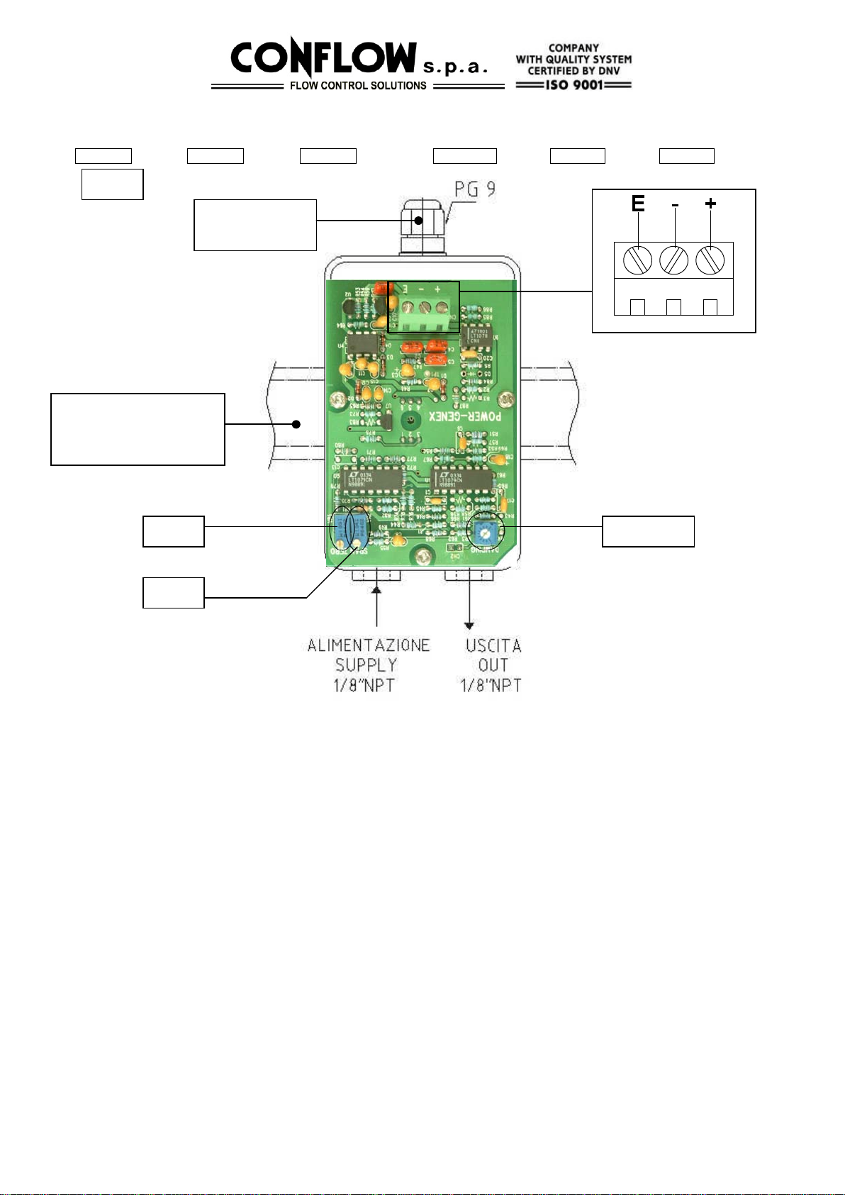
4.1 CONNESSIONI PNEUMATICHE
4.1 PNEUMATIC CONNECTIONS
Inserire aria di alimentazione nella connessione :
ALIMENTAZIONE – SUPPLY vedi fig. 1 pag. 2
secondo la seguente tabella :
Connect the air supply to the connection
ALIMENTAZIONE – SUPPLY see fig. 1 pag. 2
According to the following table :
3 – 15 psi
20 psi
3 – 15 psi
20 psi
0 – 15 psi
20 psi
0 – 15 psi
20 psi
0 – 18 psi
25 psi
0 – 18 psi
25 psi
6 – 30 psi
35 psi
6 – 30 psi
35 psi
Altri segnali Attenersi al dato segnato sulla
targa identificatrice
Other signals Operate according to the
identification plate data.
Collegare l’ USCITA – OUT vedi fig.1 pag.2 alla valvola Connect the USCITA – OUT (see fig.1 pag.2) to the valve.
Per assicurare il corretto funzionamento del convertitore, l’aria
di alimentazione deve essere libera da impurità quali olii,
polveri ecc. Utilizzare il ns. Filtro riduttore AFR35 o AFR80 che
garantisce una alto grado di filtraggio, 5
µ
std .
For a right work, the air supply must be clean, without impurity
like oils, dusts etc.
Using our AFR35 or AFR80 air filter regulator, which
guarantees an high filtration, 5
µ
std .
1
!!!
!
!!

4.2 CONNESSIONI ELETTRICHE
4.2 ELECTRIC CONNECTIONS
Rimuovere il coperchio
Inserire i due fili attraverso il passacavo fig. 1
Collegare i fili alla morsettiera interna fig. 1 contrassegnata con :
Remove the cover
Insert the two cables through the cable gland fig.1.
Connect the cables to the internal terminal board marked by:
+ Corrente - Corrente E Terra + Current - Current E Ground
5 - AVVIAMENTO
5 – START – UP
Controllare che tutti i collegamenti pneumatici ed elettrici siano
corretti.
Fornire l’alimentazione pneumatica vedi punto 4.1.
Erogare il segnale in corrente 4 – 20 mA.
Il convertitore IPC è già calibrato in fabbrica secondo quanto
richiesto dal cliente.
Check all pneumatic and electric connections are correct.
Connect the pneumatic supply see point 4.1.
Switch on the 4 – 20 mA current signal.
The IPC converter is already calibrated according to the
requests of the customer.
6 – CORREZIONE DELLO ZERO
6 – ZERO ADJUSTMENT
Per correggere lo zero agire sul trimmer contrassegnato “ZERO”
vedi fig.1.
Ruotando in senso orario si ottiene un aumento del punto di
partenza mentre ruotando in senso antiorario si ottiene un
decremento del punto di partenza
Rotate the “ZERO” trimmer (see fig.1) to adjust the zero.
Turning the trim clockwise the start point increases, turning the
trim counter clockwise the start point decreases.
7 – CORREZIONE DEL CAMPO DI MISURA
7 – MEASURING RANGE ADJUSTMENT
Per ottenere un campo diverso da quello ordinato procedere come
segue:
•Montare un manometro sulla connessione “OUT – USCITA”
•Controllare la partenza a 4 mA
•Erogare il massimo segnale 20 mA ed agire sul trimmer
“SPAN” (vedi fig.1) aumentando in senso orario e
diminuendo in senso antiorario il campo a seconda del valore
desiderato.
A tale proposito si ricorda che il convertitore IPC è in grado di
sviluppare campi in split – range (es. 4 – 12 mA o 12 – 20 mA).
To obtain a different range, see the following istructions:
•Mount a gauge on the “OUT – USCITA” connection
•Check the start at 4 mA
•Supply the max signal 20 mA and rotate the “SPAN” trim
(see fig.1). Turning the trim clockwise, the range increases,
turning the trim counter clockwise the range decreases.
Remember that the IPC converter can develop split- ranges
(ex. 4 – 12 mA or 12 – 20 mA)
8 – REGOLAZIONE DEL DUMPING (pendolamento)
8 – DUMPING ADJUSTMENT (hunting)
Se si manifesta pendolamento durante il funzionamento, ruotare il
trimmer “DUMPING” (vedi fig.1) in senso antiorario lentamente
fino ad ottenere la stabilità del segnale.
With hunting problems during the converter working, rotate the
trim “DUMPING” (see fig.1) clockwise slowly to obtain the signal
stability.
9 - MANUTENZIONE
9 – MAINTENANCE
Non sono richieste manutenzioni periodiche se l’aria di
alimentazione è secca.
Altrimenti effettuare mensilmente il
drenaggio del filtro riduttore di alimentazione.
If the air supply is dry, periodical maintenance actions are not
necessary. Otherwise drain the supply filter regulator every
month.
2
Fig.1
DUMPING
GUIDA
MOUNTING RAIL
DIN EN 50022 35 mm
PASSACAVO
CABLE GLAND
ZERO
SPAN

EU Declaration of Conformity
We herewith declare ,
Power-Genex Ltd.
99, Eunbong-ro, Namdong-gu,
Incheon 21639 Korea
declare that the DoC is issued under our sole responsibility and belongs to the following
product:
Product Name : I/P Converter
Product Model : IPC Series
The object of the declaration described above is in conformity with the relevant Union
harmonisation legislation:
Machinery Directive 2006/42/EC
EMC Directive 2004/108/EC(until 19th April, 2016) and
EMC Directive 2014/30/EU(from 20th April, 2016)
Low Voltage Directive 2006/95/EC(until 19th April, 2016) and
Low Voltage Directive 2014/35/EU(from 20th April, 2016)
The following harmonised standards and technical specifications have been applied:
BS EN ISO 12100-1 : 2003+A1:2009 / BS EN ISO 12100-2 : 2003+A1:2009 /
BS EN ISO 14121-1 : 2007 / IEC 17025 : 2005
EN 61000-6-1 : 2007 / EN 61000-6-2 : 2005 / EN61000-6-3 : 2007 / EN 61000-6-4 : 2007
ISO 9001 : 2008 Certificate : QAIC/KR/646-A
Conformity with the requirements of these Directives is proven by complete adherence to
the following standards.
- Date : Apr 20, 2016
Koh Sung-won, Head of R&D
Lee Soon-hyuk, Head of Quality Management
This declaration certifies the conformity to the specified directives but contains no assurance of properties.
Table of contents
Other CONFLOW Media Converter manuals