Conmet Conventional User manual

SERVICE MANUAL
For Steer, Drive, andTrailer Hub Assemblies
Conventional
Hub Assemblies
PreSet Plus®
Hub Assemblies
Hub & Rotor
Assemblies
PreSet®
Hub Assemblies

About this Manual
Before You Begin
-Read this manual carefully,
providing extra attention to its
explanations and instructions.
-To ensure safe, continuous,
trouble-free operation,
understand your wheel
hub system, and keep
all components in proper
operating condition.
-Pay particular attention to
all NOTES, CAUTIONS,
WARNINGS, and DANGERS
to avoid the risk of personal
injury or property damage,
and realize these statements
are not exhaustive. ConMet®
cannot possibly know or
evaluate all conceivable
methods in which service may
be performed or the possibly
hazardous consequences of
each method. Accordingly,
those who use a procedure
not recommended by ConMet
must rst satisfy themselves
that neither their safety nor
the safety of the product will
be jeopardized by the service
method selected.
-Use only ConMet approved
replacement parts. Do not
attempt to use damaged
parts.
-Follow your company’s
maintenance and service,
installation, and diagnostics
guidelines.
-Use special tools when
required to help avoid serious
personal injury and damage
to components
Color Coding
Throughout this manual we will use
the following colors to help identify
specic areas that reference
Conventional, PreSet®, and PreSet
Plus® ConMet hubs.
Conventional
PreSet
PreSet Plus
If a color is not specied, then you
can conclude the information is
mutual for all hub assemblies.
Hazard Alert Messages
A Danger alert indicates a hazardous situation
which if not avoided, will result in death or
serious injury.
DANGER
!
A Warning alert indicates a hazardous situation
which if not avoided, could result in death or
serious injury.
WARNING
!
A Caution alert indicates a hazardous situation
which if not avoided, could result in minor or
moderate injury.
CAUTION
!
A note includes additional information that may
assist the technician in service procedures.
NOTE
Additional Maintenance
and Service Information
On the Web
Visit conmet.com to access
ConMet’s product, sales, service
and maintenance literature.
ConMet Customer Service
Call ConMet’s Customer Service at
1-800-547-9473.
ConMet Decals
The following decals are available
upon request:
Decal Name PreSet Part
Number
PreSet Plus
Part Number
Disc Wheel
Installation
Procedures
103282 103282
Hubs
Lubricated
with Oil
106873 10038167
Hubs
Lubricated
with Semi-
Fluid Grease
107383 10038168
ConMet, PreSet, and PreSet Plus are registered trademarks of Consolidated Metco Inc. © Consolidated Metco Inc. 2017, All Rights Reserved.

Table of Contents
1. INTRODUCTION ..........................................................................................................................................................................................1
Conventional Hubs ............................................................................................................................................................................1
PreSet Hub Assemblies.....................................................................................................................................................................1
PreSet Plus Hub Assemblies.............................................................................................................................................................1
2. INSPECTION................................................................................................................................................................................................2
HAZARD ALERT MESSAGES .....................................................................................................................................................................2
WHEEL END INSPECTION GENERAL GUIDELINES..................................................................................................................................2
Driver Pre-Trip Visual Inspection.......................................................................................................................................................2
In Route Inspections..........................................................................................................................................................................2
Service Interval..................................................................................................................................................................................3
Lubrication Analysis ..........................................................................................................................................................................3
3. IDENTIFICATION .........................................................................................................................................................................................4
WHEEL MOUNTING SYSTEMS ..................................................................................................................................................................4
Hub Pilot Wheel Mounting .................................................................................................................................................................4
Ball Seat Wheel Mounting System.....................................................................................................................................................4
IDENTIFYING CONMET HUB ASSEMBLIES...............................................................................................................................................4
Vehicle Identication Number (VIN) ..................................................................................................................................................4
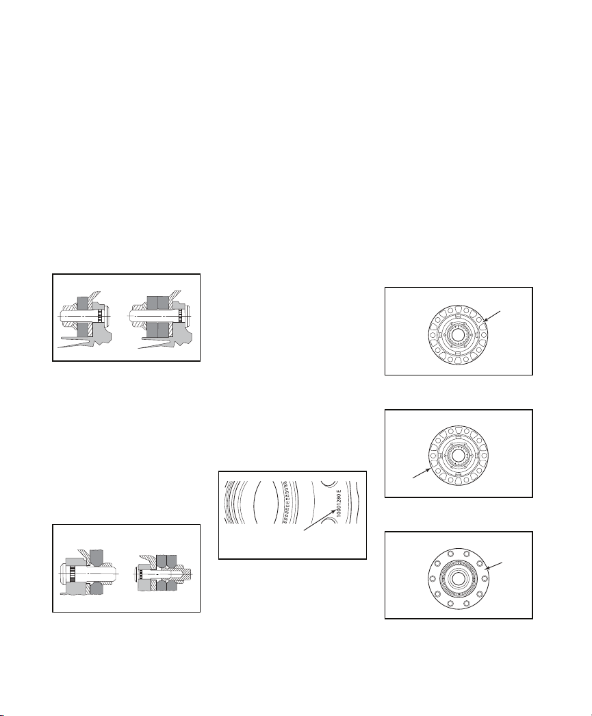
Casting Number ................................................................................................................................................................................4
Machining Number............................................................................................................................................................................4
Final Hub Assembly Number.............................................................................................................................................................5
Julian Date.........................................................................................................................................................................................5
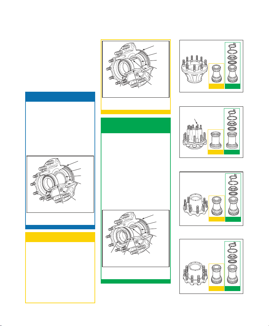
Conventional Wheel Hubs ...........................................................................................................................................................5
PreSet Wheel Hubs......................................................................................................................................................................5
PreSet Plus Wheel Hubs ..............................................................................................................................................................5
4. CONVENTIONAL WHEEL HUBS ................................................................................................................................................................6
HUB REMOVAL AND DISASSEMBLY ........................................................................................................................................................6
COMPONENT INSPECTION AND REPLACEMENT HAZARD ALERT MESSAGES....................................................................................7
CLEAN AND DRY COMPONENTS .............................................................................................................................................................7
Worn or Damaged Components .......................................................................................................................................................7
Hub and Component Cleaning .........................................................................................................................................................7
INSPECTING BEARING CUPS AND CONES..............................................................................................................................................8
REMOVING CUPS IN ALUMINUM HUBS...................................................................................................................................................8
REMOVING CUPS IN IRON HUBS .............................................................................................................................................................8
INSTALLING A NEW CUP IN ALUMINUM HUBS .......................................................................................................................................8
INSTALLING A NEW CUP IN IRON HUBS .................................................................................................................................................8
WHEEL STUDS ...........................................................................................................................................................................................9
STUD REMOVAL.........................................................................................................................................................................................9
STUD REPLACEMENT................................................................................................................................................................................9
HUB, DRUM AND WHEEL INSPECTION....................................................................................................................................................9
ABS TONE RING INSPECTION (AS APPLICABLE) ....................................................................................................................................9
REMOVAL AND INSTALLATION OF MACHINED ABS TONE RING ........................................................................................................10
REMOVAL AND INSTALLATION OF STAMPED STEEL ABS TONE RING ...............................................................................................10
REMOVAL AND INSTALLATION OF BOLT ON ABS TONE RINGS..........................................................................................................10
REASSEMBLY...........................................................................................................................................................................................11
CONVENTIONAL WHEEL HUBS ASSEMBLY...........................................................................................................................................11
REINSTALLATION ....................................................................................................................................................................................12
INSTALLING CONMET CONVENTIONAL WHEEL HUBS.........................................................................................................................12
Spindle Preparation.........................................................................................................................................................................12
Conventional Hub Installation..........................................................................................................................................................12
Manual Bearing Adjustment Procedure (reference TMC RP618) ...................................................................................................13
SERVICE PARTS .......................................................................................................................................................................................14
5. PRESET WHEEL HUBS ............................................................................................................................................................................17
HUB REMOVAL AND DISASSEMBLY ......................................................................................................................................................17
COMPONENT INSPECTION AND REPLACEMENT HAZARD ALERT MESSAGES..................................................................................18
CLEAN AND DRY COMPONENTS ...........................................................................................................................................................19
Worn or Damaged Components .....................................................................................................................................................19
Hub and Component Cleaning .......................................................................................................................................................19
INSPECTING BEARING CUPS AND CONES AND BEARING SPACER ...................................................................................................19
REMOVING CUPS IN ALUMINUM HUBS.................................................................................................................................................19
REMOVING CUPS IN IRON HUBS ...........................................................................................................................................................20
INSTALLING A NEW CUP IN ALUMINUM HUBS .....................................................................................................................................20
INSTALLING A NEW CUP IN IRON HUBS ...............................................................................................................................................20
WHEEL STUDS .........................................................................................................................................................................................20
STUD REMOVAL.......................................................................................................................................................................................20
STUD REPLACEMENT..............................................................................................................................................................................20
HUB, DRUM AND WHEEL INSPECTION..................................................................................................................................................21
ABS TONE RING INSPECTION (AS APPLICABLE) ..................................................................................................................................21
REMOVAL AND INSTALLATION OF ABS TONE RING ............................................................................................................................21
REMOVAL AND INSTALLATION OF STAMPED STEEL ABS TONE RING ...............................................................................................21
REMOVAL AND INSTALLATION OF BOLT ON ABS TONE RINGS (FOR DISC BRAKES).......................................................................22
REASSEMBLY...........................................................................................................................................................................................23
PRESET WHEEL HUBS.............................................................................................................................................................................23

Table of Contents
REINSTALLATION ....................................................................................................................................................................................25
INSTALLING THE PRESET WHEEL HUB ASSEMBLY ..............................................................................................................................25
Spindle Preparation.........................................................................................................................................................................25
Mounting the Hub............................................................................................................................................................................25
Spindle Nut Torque .........................................................................................................................................................................25
SERVICE PARTS .......................................................................................................................................................................................26
6. PRESET PLUS WHEEL HUBS..................................................................................................................................................................29
HUB REMOVAL AND DISASSEMBLY ......................................................................................................................................................29
COMPONENT INSPECTION AND REPLACEMENT HAZARD ALERT MESSAGES..................................................................................31
CLEAN AND DRY COMPONENTS ...........................................................................................................................................................31
Worn or Damaged Components .....................................................................................................................................................31
Hub and Component Cleaning .......................................................................................................................................................31
INSPECTING BEARING CUPS AND CONES AND BEARING SPACER ...................................................................................................31
REMOVING CUPS IN ALUMINUM HUBS.................................................................................................................................................32
REMOVING CUPS IN IRON HUBS ...........................................................................................................................................................32
INSTALLING A NEW CUP IN ALUMINUM HUBS .....................................................................................................................................32
INSTALLING A NEW CUP IN IRON HUBS ...............................................................................................................................................32
WHEEL STUDS .........................................................................................................................................................................................32
STUD REMOVAL.......................................................................................................................................................................................33
STUD REPLACEMENT..............................................................................................................................................................................33
HUB, DRUM AND WHEEL INSPECTION..................................................................................................................................................33
ABS TONE RING INSPECTION (AS APPLICABLE) ..................................................................................................................................33
REMOVAL AND INSTALLATION OF ABS TONE RING ............................................................................................................................33
REMOVAL AND INSTALLATION OF STAMPED STEEL ABS TONE RING ...............................................................................................34
REMOVAL AND INSTALLATION OF BOLT ON ABS TONE RINGS (FOR DISC BRAKES).......................................................................34
REASSEMBLY...........................................................................................................................................................................................35
PRESET PLUS WHEEL HUBS...................................................................................................................................................................35
Spindle Nut and Spiral Snap Ring Reassembly..............................................................................................................................36
REINSTALLATION ....................................................................................................................................................................................37
INSTALLING THE PRESET PLUS WHEEL HUB ASSEMBLY ....................................................................................................................37
SERVICE PARTS .......................................................................................................................................................................................38
7. LUBRICATION ...........................................................................................................................................................................................41
DRIVE HUB LUBRICATION ......................................................................................................................................................................41
STEER AND TRAILER HUBS WITH OIL LUBRICANT...............................................................................................................................41
TRAILER HUBS WITH SEMI-FLUID GREASE LUBRICANT ......................................................................................................................41
8. BRAKE AND WHEEL INSTALLATION......................................................................................................................................................43
CALIPER INSTALLATION .........................................................................................................................................................................43
WHEEL INSTALLATION............................................................................................................................................................................43
HUB PILOT WHEEL MOUNTING SYSTEM ...............................................................................................................................................43
BALL SEAT WHEEL MOUNTING SYSTEM ...............................................................................................................................................44
9. WHEEL HUB AND ROTOR........................................................................................................................................................................46
WHEEL HUBS WITH CONMET DISC BRAKE ROTORS ...........................................................................................................................46
Part Number Identication...............................................................................................................................................................46
Rotor Identication ..........................................................................................................................................................................46
10. HUB AND ROTOR INSPECTION...............................................................................................................................................................47
HAZARD ALERT MESSAGES ...................................................................................................................................................................47
DISC BRAKE ROTOR INSPECTION .........................................................................................................................................................47
Heat Checks....................................................................................................................................................................................47
Cracks .............................................................................................................................................................................................47
Deep Grooves or Scoring................................................................................................................................................................48
Blue Marks or Bands .......................................................................................................................................................................48
Polished Rotors ...............................................................................................................................................................................48
Martensite Spotted Rotors...............................................................................................................................................................48
Grease-Stained Rotors ....................................................................................................................................................................48
Lining Transfer.................................................................................................................................................................................49
Clogged or Restricted Vent Holes...................................................................................................................................................49
Rotor Runout....................................................................................................................................................................................49
Rotor Thickness...............................................................................................................................................................................49
Rotor Resurfacing............................................................................................................................................................................50
11. HUB AND ROTOR REMOVAL AND DISC REPLACEMENT ....................................................................................................................51
HAZARD ALERT MESSAGES ...................................................................................................................................................................51
HUB AND ROTOR REMOVAL ..................................................................................................................................................................51
DISC BRAKE ROTOR REPLACEMENT.....................................................................................................................................................51
PART IDENTIFICATION ............................................................................................................................................................................51
12. DISC BRAKE ROTOR REPLACEMENT ...................................................................................................................................................52
ROTOR REPLACEMENT PROCEDURES..................................................................................................................................................52
ConMet Flat Rotors..........................................................................................................................................................................52
ConMet Hat Rotor............................................................................................................................................................................62
ConMet U-Shaped Rotors ...............................................................................................................................................................63
WHEEL HUB AND ROTOR – SERVICE PARTS LIST ..............................................................................................................................67
WHEEL TORQUE SPECIFICATIONS........................................................................................................................................................68

Conventional Hubs
ConMet conventional hubs feature
precision-machined aluminum or
iron castings and are available in
steer, drive and trailer congurations.
Hubs are supplied with bearing cups
and studs installed. Bearing cones
and wheel seals are supplied by the
customer. Bearings must be adjusted
manually. See TMC RP618 for
specics of adjustment procedures.
1
106923a
ABS RING
INNER
BEARING
CONE
INNER
BEARING
CUP
OUTER
BEARING
CUP
OUTER
BEARING
CONE
LUBRICANT
FILL PLUG
OIL SEAL
Conventional Hub and Components
FIGURE 1
PreSet®Hub Assemblies
ConMet PreSet hub assemblies
include precision-machined hubs,
premium seals, specially toleranced
roller bearings and unique precision-
machined bearing spacers. This
combination eliminates the need
to manually adjust wheel end play.
These components are delivered as
a complete assembly, reducing the
potential for premature failures due
to incorrect end play settings and/or
improper installation practices.
1ConMet
1. Introduction
ConMet offers three types of wheel
hubs:
-Conventional hubs with
manually-adjusted bearings
-PreSet hub assemblies with
pre-adjusted bearings
-PreSet Plus hub assemblies
with pre-adjusted bearings
and an integrated spindle nut
PreSet Plus®Hub
Assemblies
ConMet PreSet Plus hub assemblies
feature the same PreSet technology
and include the same precision-
machined hubs, premium seals
and specially toleranced roller
bearings. However, PreSet Plus hubs
incorporate the following:
-An integrated spindle nut
that eases installation and
disassembly and protects
components during wheel end
service
-An optimized spacer
-Standard magnetic ll plug
1
106922a
ABS RING
INNER
BEARING
CONE
INNER
BEARING
CUP
OUTER
BEARING
CUP
OUTER
BEARING
CONE
INTEGRATED
NUT
LUBRICANT
FILL PLUG
OIL SEAL
SPACER
(SECTIONED)
PreSet Plus Hub and Components
FIGURE 3
1
106924a
ABS RING
INNER
BEARING
CONE
INNER
BEARING
CUP
OUTER
BEARING
CUP
OUTER
BEARING
CONE
LUBRICANT
FILL PLUG
SPACER
(SECTIONED)
OIL SEAL
PreSet Hub and Components
FIGURE 2
2
106876a
MACHINED
STEER HUB
PRESET
COMPONENTS
PRESET PLUS
COMPONENTS
Steer Hub and Components
FIGURE 4
3
106818c
MACHINED
DRIVE HUB
NOTE: CAN BE WITH
OR WITHOUT
AXLE STUDS.
PRESET
COMPONENTS
PRESET PLUS
COMPONENTS
Drive Hub and Components
FIGURE 5
4
106819c
MACHINED
TN TRAILER HUB
PRESET
COMPONENTS
PRESET PLUS
COMPONENTS
TN Trailer Hub and Components
FIGURE 6
5
106820c
MACHINED
TP TRAILER HUB
PRESET
COMPONENTS
PRESET PLUS
COMPONENTS
TP Trailer Hub and Components
FIGURE 7

2ConMet
2. Inspection
HAZARD ALERT
MESSAGES
Read and observe all hazard alert
messages in this publication. They
provide information that can help
prevent serious personal injury,
damage to components, or both.
Do not work under a vehicle supported only by
jacks. Jacks can slip and fall over. Serious personal
injury and damage to components can result.
Park the vehicle on a level surface. Block the
wheels to prevent the vehicle from moving.
Support the vehicle with safety stands.
To prevent serious eye injury, always wear
safe eye protection when you perform vehicle
maintenance or service.
WARNING
!
WHEEL END INSPECTION
GENERAL GUIDELINES
Operating temperature can be checked as the
vehicle enters the service area following a normal
run. If the hub is running in excess of 150°F above
the ambient temperature in normal operating
conditions, service is required.
NOTE
Wheel end service and
maintenance requirements will
vary based on vehicle operating
conditions, vehicle specications,
lubrication type, and vehicle
performance history. Consolidated
Metco recommends the
maintenance schedule below, in
conjunction with TMC RP631A, to
be adjusted as needed for varying
conditions.
If any item is found to be out of specication
during any of the inspection steps listed below,
place the vehicle out of service until the item can
be repaired or replaced.
CAUTION
!
Driver Pre-Trip Visual
Inspection
Visually inspect the vehicle prior
to operation. Include the following
items:
1. Check for loose, damaged, or
missing fasteners on the wheel
and hub cap or axle. Rust or
dark streaks coming from the
wheel bolts may be a sign of
improper wheel bolt torque.
2. Check for loose, damaged, or
missing hubcaps.
3. Check for lubricant leaks at:
-Hubcap
-Drive axle ange gasket
-Oil ll plug
-Oil seal leakage – indicated
by lubricant on the hub, brake
components or inside of the
wheel
4. Check lubricant condition via
hub cap window on steer and
trailer hubs. Lubricant that is
darkened, milky, shows water
in it, or has large metallic
particles in it is indicative
of contamination or a part
failure and must be replaced.
Contaminated lubricant may be
an indication of a leaking seal
that should be replaced.
5. Check for insufcient lubricant
level via hub cap window on
steer and trailer hubs. Rell
lubricant to the indicated ll
level if required.
If any of the above conditions
are found, place the vehicle out
of service until the item can be
repaired.
In Route Inspections
1. After making an in route stop,
walk around the vehicle and
inspect the hubs for any leaks
(per item 3 under Driver Pre-
Trip) and signicant differences
in temperature or excessive
temperature. If excessive
temperature is found, inspect
and repair the wheel end as
necessary. High temperatures
and high loads may cause
early bearing failure. Lubricant
viscosity should be chosen
based on expected operating
temperatures.
Preventative Maintenance
Schedule
During any routine preventative
maintenance on the vehicle or axle
(see your OEM guidelines and
associated federal regulations),
inspect the following items:
1. Check for loose, damaged, or
missing fasteners on the wheel
and hub cap. Rust or dark
streaks coming from the wheel
bolts may be a sign of improper
wheel bolt torque.
2. Check for loose, damaged, or
missing hubcaps.
3. Check for lubricant leaks at:
-Hubcap
-Drive axle ange gasket
-Oil ll plug
-Oil seal – indicated by
lubricant on the hub, brake
components or inside of the
wheel
4. Check for insufcient lubricant
level via hub cap window on
steer and trailer hubs. Rell
lubricant to the indicated ll
level if required.

3ConMet
2. Inspection (continued)
5. Check the lubricant condition.
Lubricant that is darkened,
milky, shows water in it or has
large metallic particles in it is
indicative of contamination
or a part failure and must
be replaced. Contaminated
lubricant may be an indication
of a leaking seal that should be
replaced.
-On oil lubricated hubs
equipped with a ll plug in
the hubcap or barrel of the
hub, place a magnet (or
inspect the magnetic ll plug)
in the lubricant and check
for signs of large metallic
particles picked up by the
magnet. On drive axles,
it is normal to nd a small
amount of very ne metallic
particles from the carrier
housing on the magnetic
ll plug. These particles
should be removed from the
magnet anytime the plug is
removed for inspection. If
larger particles or chunks
of metal are found, the hub
should be removed from the
spindle and the bearings and
other components should
be inspected for signs of
damage or excessive wear.
-In vehicles without a ll
plug in drive hubs inspect
the lubricant volume and
condition from the ll plug in
the axle carrier housing.
-For vehicles lubricated with
semi-uid grease, inspect
annually or every 100,000
miles. First, remove the
hubcap and inspect the
lubricant condition and
volume. Verify the lubricant
covers the ends of the
bearing rollers. If the lubricant
condition is good, add
lubricant through the ll plug
in the barrel of the hub to
cover the ends of the bearing
rollers. If the lubricant has a
dry and caked appearance,
remove the wheel end from
the vehicle and clean and
inspect all components.
Replace damaged or worn
components as necessary.
Rell hub with semi-uid
grease amount per chart on
page 42.
6. If regular scheduled
maintenance requires wheels/
axle to be lifted, perform steps
7 and 8.
7. Lift and support the axle (see
gure 8). Rotate the wheel.
Check that the wheel rotates
freely and smoothly. Listen
and feel for any signs of rough
bearing operation or vibration.
6
1003159a
FIGURE 8
8. Place your hand on the top of
the tire and use a pry bar to lift
the bottom of the tire to check
for loose bearings or “chucking”
(see gure 9). If excess
movement or “chucking” is
found, wheel end service is
required.
Before you check for chucking, be sure to grease
the king pins.
NOTE
7
106878a
FIGURE 9
If any of the above conditions
are found, place the vehicle out
of service until the item can be
repaired.
Service Interval
Inspection results at driver pre-
trip, in-route and preventative
maintenance will indicate whether
further service is required.
When inspections indicate that
service is necessary, follow the
recommended service, inspection,
reassembly and reinstallation
instructions found in the following
sections of this manual.
Lubrication Analysis
Beyond the recommended visual
inspection and inspection with
a magnet, develop a lubrication
testing and replacement program.
This program will depend on
vehicle application, and lubrication
type. A lubricant supplier should
be consulted for additional
lubricant inspection and testing
recommendations.

4ConMet
3. Identication
WHEEL MOUNTING
SYSTEMS
ConMet wheel hubs are available
in both hub pilot and ball seat nut
congurations.
Hub Pilot Wheel Mounting
The hub pilot wheel mounting
system makes use of a single
two-piece ange nut on each wheel
stud for both single and dual wheel
applications (see gure 10). The
hub pilot wheel mounting system is
also known as the Uni-Mount-10™
(10 stud), WHD-10™ (10 stud),
WHD-8™ (8 stud), and ISO system.
8
106821a
SINGLE DUAL
Hub Pilot Mounting System
FIGURE 10
Ball Seat Wheel Mounting System
The ball seat wheel mounting
system makes use of the spherical
contact area between the nut and
wheel to both locate the wheel and
hold the wheel tight against the
brake drum (see gure 11).
The ball seat wheel mounting
system is also known as the stud
piloted, ball seat cap nut (BCN)
and double cap nut (DCN) system.
9
106822a
SINGLE DUAL
Ball Seat Mounting System
FIGURE 11
IDENTIFYING CONMET
HUB ASSEMBLIES
Identifying your hub assembly
is important for many reasons.
It will enable you to properly
service the hub assembly
and purchase the appropriate
replacement parts if needed. Plus,
if a warranty issue arises, you’ll
then be able to provide details on
all aspects of the ConMet hub.
This section is devoted to nding
and understanding the different
identication numbers associated
with ConMet hubs.
Vehicle Identication Number
(VIN)
The quickest and easiest method
of identifying your hub assembly
is to note the vehicle identication
number (VIN) and call the truck
dealership. The dealership can
then tell you what hubs were
installed on your vehicle. If this is
not possible, there is a variety of
identication numbers located on a
ConMet hub assembly.
Casting Number
This number is physically cast
into the hub and appears in large
characters usually on the back side
of the mounting ange near the
stud head (see gure 12).
10
106829a
CASTING NUMBER ONTHE
BACK SIDE OF THE
MOUNTING FLANGE
Casting Number on the Back Side of
the Mounting Flange
FIGURE 12
Machining Number
This number is stamped on one of
the following:
-Mounting ange face (see
gure 13)
-Diameter of the mounting
ange (see gure 14)
-Back side of the mounting
ange (see gure 15)
-Barrel of the hub (see gure
16)
The machining number represents
the way the hub is machined
(e.g., hub pilot vs. ball seat, 8.78”
vs. 8.53” vs. 9” brake drum pilot
diameter).
11
106828a
MOUNTING FLANGE FACE
Mounting Flange Face
FIGURE 13
12
106825b
MOUNTING FLANGE DIAMETER
Mounting Flange Diameter
FIGURE 14
13
106826a
MOUNTING FLANGE BACKFACE
Mounting Flange Backface
FIGURE 15

PreSet Plus®Hub
Assemblies
For instructions on installing ConMet's
PreSet Plus hub assemblies (see
gure 19), refer to the PreSet hub
assembly reinstallation instructions
in section 6.
17
PreSet Plus Hub Assembly
FIGURE 19
Conventional Hubs
For instructions on installing ConMet’s
Conventional hub (see gure 17),
refer to the Conventional reinstallation
instructions in section 4.
15
PreSet Plus Hub Assembly
FIGURE 19
PreSet®Hub Assemblies
For instructions on installing
ConMet’s PreSet hub assemblies
(see gure 18), refer to the PreSet
hub reinstallation instructions in
section 5.
16
PreSet Hub Assembly
FIGURE 18
5ConMet
3. Identication (continued)
14
106827a
BARREL OF HUB
Barrel of Hub
FIGURE 16
Final Hub Assembly Number
This number is stamped on one of
the following:
-Mounting ange face (see
gure 13)
-Diameter of the mounting
ange (see gure 14)
-Back side of the mounting
ange (see gure 15)
The nal hub assembly number
identies the hub assembly,
hub machining, studs, bearings,
spacer, seal and ABS ring.
Julian Date
The casting, machining, and the
nal assembly have Julian dates
stamped into the hub assembly in
the same location as the assembly
numbers (see gures 13, 14, 15
and 16). A Julian date appears as
the day of the year plus the last
two digits of the calendar year
(e.g., July 4 2008 would appear as
18508). This number provides the
date when the hub was machined
and assembled at the factory
and may be used for warranty
purposes.

Conventional Hubs
ConMet conventional hubs feature
precision-machined aluminum or
iron castings and are available in
steer, drive and trailer congurations.
Hubs are supplied with bearing
cups and studs installed. Bearing
cones and seal are supplied by the
customer. Bearings must be adjusted
manually. See TMC RP618 specics
of adjustment procedures.
18
106923a
ABS RING
INNER
BEARING
CONE
INNER
BEARING
CUP
OUTER
BEARING
CUP
OUTER
BEARING
CONE
LUBRICANT
FILL PLUG
OIL SEAL
Conventional Hub and Components
FIGURE 20
6
Conventional Wheel Hubs – Recommended Service
ConMet
4. Conventional Wheel Hubs – Recommended Service
When inspections indicate
that service is necessary on a
conventional hub, follow the
recommended service, inspection,
reassembly and reinstallation
instructions found in the following
section.
HUB REMOVAL AND
DISASSEMBLY
Vehicles on jacks can fall, causing serious personal
injury or property damage.Never work under a
vehicle supported by a jack without supporting
the vehicle with stands and blocking the wheels.
Wear safe eye protection.
WARNING
!
1. Park the vehicle on a level
surface. Block the wheels to
prevent the vehicle from moving.
2. Raise the axle until the tires are
off the oor.
3. Place safety stands under the
trailer frame or under each axle
spring seat (see gure 21).
19
1003159a
FIGURE 21
4. Remove the tire and wheel
assembly using procedures
specied by the wheel
manufacturer (see gure 22).
20
103160a
FIGURE 22
Sudden release of compressed air can cause serious
personal injury and damage to components.
Before you service a spring chamber, carefully
follow the manufacturer’s instructions to compress
and lock the spring to completely release the
brake.Verify that no air pressure remains in the
service chamber before you proceed.
WARNING
!
5. If the axle is equipped with
spring brake chambers,
carefully compress and lock
the springs so that they cannot
actuate (see gure 23).
21
103161a
FIGURE 23
6. For drum brakes, remove
the brake drum. Support the
drum during the removal
process to prevent damage
to the components. For disc
brakes, remove caliper per
manufacturers’ recommended
procedure.
If the hub to be disassembled is a drive hub,
remove the drive axle shaft, and capture the oil
(see gure 24).
NOTE
22
106803a
Removing the Drive Axle Shaft
FIGURE 24
7. Place a container under the
hubcap, or drive axle shaft
for a drive hub, to receive the
draining oil, then remove the
hubcap or drive axle shaft.
Do not reuse the oil. Correctly
dispose of the lubricant.
8. Examine the spindle nut to
determine the type of locking
system. Disengage the locking
device.
Do not loosen the axle spindle nuts by either
striking them directly with a hammer, or striking
a drift or chisel placed against them. Damage to
the parts will occur causing possible loss of axle
wheel-end components and serious personal
injury.
WARNING
!
9. Remove the spindle nut system.

7
Conventional Wheel Hubs – Recommended Service
ConMet
4. Conventional Wheel Hubs – Recommended Service
10. Slide the hub off the spindle.
Remove and save the outer
bearing cone. Be careful when
you remove the hub that you do
not damage the outer bearing
by dropping it on the oor.
-If the hub is difcult to remove
because the seal or bearings
are stuck on the spindle, use
a mechanical puller to remove
the hub (see gure 25).
-If part of the seal remains on
the spindle, carefully remove
the part of the seal that
remains on the spindle.
This can be done by striking the remaining portion
of the seal with the round end of a ball-peen
hammer. Use caution not to damage the seal
journal on the spindle.
NOTE
23
105740a
FIGURE 25
11. Place the hub on its outboard
end and remove the seal.
Retain the seal if it needs
to be returned for warranty
consideration.
12. Remove the inner bearing cone
(see gure 26).
24
106804b
INNER
BEARING
CONE
Hub Disassembly
FIGURE 26
COMPONENT
INSPECTION AND
REPLACEMENT HAZARD
ALERT MESSAGES
Read and observe all hazard alert
messages in this publication. They
provide information that can help
prevent serious personal injury,
damage to components, or both.
To prevent serious eye injury, always wear
safe eye protection when you perform vehicle
maintenance or service.
Observe all warnings and cautions provided
by the press manufacturer to avoid damage to
components and serious personal injury.
Do not hit steel parts with a steel hammer. Pieces
of a part can break o. Serious personal injury and
damage to components can result. Use a brass or
synthetic mallet for assembly and disassembly
procedures.
Solvent cleaners can be ammable, poisonous
and cause burns. Examples of solvent cleaners
are carbon tetrachloride, and emulsion-type
and petroleum-base cleaners. Read the
manufacturer’s instructions before using a solvent
cleaner, then carefully follow the instructions. Also
follow the procedures below.
- Wear safe eye protection.
- Wear clothing that protects your skin.
- Work in a well-ventilated area.
- Do not use gasoline or solvents that contain
gasoline. Gasoline can explode.
- You must use hot solution tanks or alkaline
solutions correctly. Read the manufacturer’s
instructions before using hot solution tanks
and alkaline solutions.Then carefully follow
the instructions.
WARNING
!
Do not use hot solution tanks or water and
alkaline solutions to clean ground or polished
parts. Damage to parts can result.
CAUTION
!
CLEAN AND DRY
COMPONENTS
Worn or Damaged Components
Do not repair or recondition wheel-end
components. Replace damaged, worn or out-of-
specication components. Do not mill or machine
any components. Using repaired, reconditioned,
damaged or worn components can cause wheel
end failure, which can result in serious injury and
property damage.
WARNING
!
Hub and Component Cleaning
1. Use a cleaning solvent to clean
the hub and all wheel end
components.
2. Do NOT clean ground or
polished parts in a hot solution
tank or with water, steam
or alkaline solutions. These
solutions will cause corrosion of
the parts.
3. Clean and inspect the wheel
bearing cups and cones,
race, spindle bearing and seal
journals on the spindle and hub.
Bearings should be cleaned
with clean ltered solvent and
dried with either compressed
air or a lint-free rag.
If compressed air is used, do not spin dry the
bearings.The rollers may score due to lack of
lubricant and rollers could come o which can
result in serious injury. Ensure that the air line is
moisture free.
CAUTION
!
4. Clean and inspect the spindle.
Be sure to clean the full length
of the seal journal on the
spindle.
5. Parts must be dried
immediately after cleaning. Dry
parts with clean paper towels or
rags, or compressed air. Do not
dry bearings by spinning with
compressed air.

8
Conventional Wheel Hubs – Recommended Service
ConMet
4. Conventional Wheel Hubs – Recommended Service
6. Apply a light oil to cleaned
and dried parts that are not
damaged and are to be
immediately assembled. Use
only the type of oil used by the
manufacturer. Do NOT apply oil
to the brake linings or the brake
drums.
7. If the parts are to be stored,
apply a good corrosion
preventative to all surfaces.
Do NOT apply the material to
the brake linings or the brake
drums. Store the parts inside
special paper or other material
that prevents corrosion.
INSPECTING BEARING
CUPS AND CONES
If you choose to reuse existing bearings at this
service, they must be inspected in accordance
with the bearing manufacturers recommended
guidelines.
CAUTION
!
If this inspection indicates that existing bearing
component(s) must be replaced, bearing cups and
cones must be replaced as a set.
CAUTION
!
After components have been
properly cleaned, visually inspect
the cups and cones for any wear
or damage. Reference TMC RP644
for proper component inspection
procedures.
REMOVING CUPS IN
ALUMINUM HUBS
1. If the bearing cup must be
removed from an aluminum
hub, remove it by welding a
large bead around the bearing
surface of the steel cup,
letting the assembly cool, and
removing the bearing cup (see
gure 27).
If a welder is not available, heat the hub in an
oven to a temperature not to exceed 300°F and
pound out the bearing cups with a hammer
and mild steel bar, being careful not to damage
the hub.
NOTE
25
106856a
Welding Bead
FIGURE 27
2. Inspect the bearing cup bore
for evidence of cup rotation or
spun cups.
-If cup rotation exists, replace
the hub.
REMOVING CUPS IN
IRON HUBS
1. On an iron hub, remove the
bearing cup using a large
hammer and a mild steel bar
or a hydraulic press. Take
precaution to avoid damaging
the bearing cup bore and
shoulder.
2. Inspect the bearing cup bore
for evidence of cup rotation or
spun cups.
-If cup rotation exists, replace
the hub.
INSTALLING A NEW CUP
IN ALUMINUM HUBS
To install a new cup in an aluminum
hub, it is recommended that
the hub be heated in boiling
water (212°F) or in an oven at a
temperature not to exceed 300°F.
Cooling the cup in a freezer to
32°F or below will further ease the
installation.
Do not overheat the hub as it may degrade the
heat-treated strength of the hub. Do not heat the
hub with a torch or open ame.
WARNING
!
Remove the aluminum hub from the
oven or water and carefully drop in
the new bearing cup being certain
it is fully seated. If the cup is loose,
allow a few seconds for it to heat up
and secure itself before moving the
hub. Use a 0.001″ to 0.002″ feeler
gauge to ensure the cup is fully
seated against the shoulder of the
bearing bore.
INSTALLING A NEW CUP
IN IRON HUBS
Iron hubs do not need to be heated
for bearing cup installation. Press
the bearing cup into the hub, being
certain that it is fully seated (see
gure 28). Use a 0.001″ to 0.002″
feeler gauge to ensure the cup is
fully seated against the shoulder of
the bearing bore.
26
105742a
Bearing Cup Pressed into Hub
FIGURE 28

9
Conventional Wheel Hubs – Recommended Service
ConMet
4. Conventional Wheel Hubs – Recommended Service
WHEEL STUDS
Replace all wheel studs that have
damaged or distorted threads,
are broken or bent, or are badly
corroded. Also, replace both
studs adjacent to the damaged
stud. If two or more studs have
damage, replace all the studs in
the hub. Broken studs are usually
an indication of excessive or
inadequate wheel nut torque.
STUD REMOVAL
Observe all warnings and cautions for press
operation provided by the press manufacturer
to avoid serious personal injury and damage to
components.
WARNING
!
1. Place the clean hub in a shop
press with the hub supported
evenly around and adjacent to
the stud being removed.
Failure to adequately support the hub can result
in physical injury and/or damage to the hub.Some
hubs are congured so it is impractical to have
supports to prevent the hub from tipping when
force is applied to the stud. In this case, support
the hub on wood blocks on the oor and use a
heavy hammer to drive the studs out with several
sharp blows. Be careful to avoid damaging the
hub and components, particularly the seal bore
and the ABS tone ring.
WARNING
!
2. Press the stud out of the hub.
STUD REPLACEMENT
On the ball seat wheel mounting system, always
use left-handed threaded studs, which are gold in
color and have an“L”stamped on the end, in the
hub on the driver’s side of the equipment, and use
right-handed threaded studs, which are silver in
color and have an“R”stamped on the end, in the
hub on the passenger’s side of the equipment.
The ConMet part number is located on the head
of the stud.The same part number must be used
for replacement unless changing the drum or
wheel type.
CAUTION
!
1. To install a new stud, support
the hub evenly around and
adjacent to the stud being
installed.
2. Press the new stud all the way
into the hub. Be sure the stud
is fully seated and that the stud
head is not embedded into the
hub.
Excessive force can cause the stud head to be
embedded into the hub, which can create a crack
in the hub, resulting in serious injury and property
damage. If a stud head is embedded in a hub,
replace the hub.
WARNING
!
HUB, DRUM AND WHEEL
INSPECTION
1. Inspect the drum pilots, wheel
pilots, and mounting face on the
hub for damage. A damaged
drum pilot is usually caused
by improper drum mounting. A
damaged wheel pilot could be
the result of inadequate wheel
nut torque, allowing the wheels
to slip in service. Also, inspect
other surfaces of the hub for
signs of cracks or damage.
2. Inspect the wheels and brake
drum for damage.
Do not repair or recondition wheel-end
components. Replace damaged, worn or out-of-
specication components. Do not mill or machine
any components. Using repaired, reconditioned,
damaged or worn components can cause wheel
end failure, which can result in serious injury and
property damage.
WARNING
!
ABS TONE RING
INSPECTION (AS
APPLICABLE)
The Anti-Lock Braking System
(ABS) signals acts like any signal
generator where the magnet
passes a coil and generates a
current. On hubs, the toothed ring
passes a sensor and generates
a signal that is sent to the ABS
computer. There are three types of
ABS rings used on ConMet hubs —
machined, stamped steel and bolt
on (see gure 29).
27
106805b
MACHINED
ABS RING
STAMPED STEEL
ABS RING
BOLT ON
ABS RING
FIGURE 29
If the tone ring is damaged (for
example, if it is dropped, bent,
chipped or dinged), it must be
replaced. For a list of replacement
ABS rings, refer to the Service Parts
List in the back of this section.

10
Conventional Wheel Hubs – Recommended Service
ConMet
REMOVAL AND
INSTALLATION OF
MACHINED ABS
TONE RING
For a machined ring, remove
using a chisel, making sure not to
damage the hub (see gure 30).
Reinstall by heating the ring to
350°F in an oven and installing it on
the hub.
28
106806a
Machined ABS Ring
FIGURE 30
REMOVAL AND
INSTALLATION OF
STAMPED STEEL ABS
TONE RING
1. The steer axle tone ring can be
removed by gripping the ring
with a pair of locking pliers and
tapping the pliers upward with
a rubber mallet. Work around
the ring to keep the ring from
cocking (see gure 31). Drive
axle and trailer tone rings can
be removed by gripping the
ring with a pair of locking pliers
and prying against the head of
a wheel stud to lift the ring off
the hub. Work around the ring to
prevent cocking (see gure 32).
29
106807a
Stamped Steel ABS Ring
FIGURE 31
30
106808a
Stamped Steel ABS Ring
FIGURE 32
2. Thoroughly clean and degrease
the ABS ring seat on the hub
with a nonammable solvent.
Replace the hub if the ABS ring seat is damaged.
The ABS ring must be fully seated with a
maximum of 0.008" axial runout to ensure the
ABS system functions properly.
CAUTION
!
For steer hubs, be certain the inside diameter
ange is facing up.
NOTE
3. Place the hub in a press and
place the ABS ring on the hub
ring seat.
4. Using ConMet ring installation
tool (part number 107119),
center the tool over the ABS
ring. Each type of ring ts a
corresponding diameter on the
tool (see gure 33).
31
105744a
Installing the ABS Tone Ring
FIGURE 33
5. Press the ring on the hub. If a
press is not available, drive the
ring on with a hammer or mallet
until the ring seats on the hub
(see gure 34). A swift initial
blow with an 8-lb. hammer may
be necessary to start the ring
onto the hub.
32
105745a
Using a Hammer to Install the Ring
FIGURE 34
6. Inspect the ring to ensure
proper seating. If the ring is not
completely seated, continue
to drive the ring with the
ring installation tool until it is
completely seated.
REMOVAL AND
INSTALLATION OF BOLT
ON ABS TONE RINGS
1. Remove and discard the
fasteners holding the ABS tone
ring on the hub.
2. Thoroughly clean and degrease
the ABS ring seat on the hub
with a non-ammable solvent.
3. Install the new ABS ring using
the new fasteners included with
the ring. Torque the fasteners to
the torque specications below.
Thread Size Torque
#8-32 18-22 in-lbs
1/4"-20 155-165 in-lbs
4. Conventional Wheel Hubs – Recommended Service

11ConMet
Conventional Wheel Hubs – Reassembly
4. Conventional Wheel Hubs – Reassembly
CONVENTIONAL WHEEL
HUBS REASSEMBLY
When using an oil bath system, do not pack the
bearing with grease. Grease will prevent the
proper circulation of axle lubricant and can cause
premature wheel seal and bearing failure.
CAUTION
!
1. Place the hub, seal end up, on
a clean work surface.
2. Lubricate the inner bearing
cone with the same lubricant
as will be used in the hub and
install it into the inner bearing
cup (see gure 35).
33
106810a
Bearing Cone Assembly
FIGURE 35
The seal must be replaced every time the hub is
removed from the spindle.
Do not apply any gasket sealant to the seal outer
or inner diameter.
Always use the seal installation tool specied by
the seal manufacturer. Using an improper tool can
distort or damage the seal and cause premature
seal failure.
NOTE
3. Position the seal into the hub
bore. Use a ConMet seal
installation tool or at plate and
a small mallet to install the seal.
ConMet seals require the proper tool for
installation. Refer to the tables below for
a ConMet seal installation tool or at plate
dimensions. For other seals, refer to the specic
manufacturers’instructions.
NOTE
ConMet Installation Tools
Axle Type Part Number
FF Steer 10084010
FL Steer 10084011
R-Drive 10084012
TN-Trailer 10084013
TP-Trailer 10084013
Flat Plate Dimensions
Application Seal Part
Number
Min.
Dia.
Max.
Dia.
FF Steer 10045885 4.45" 4.65"
FL Steer 10045883 5.2" 5.4"
R-Drive 10045887 5.6" 5.85"
TN-Trailer 10045888 5.6" 5.85"
TP-Trailer 10045889 5.6" 5.85"
4. When installing the ConMet
seal, tap the adapter plate of
the installation tool around the
outer edge to position the seal.
Drive the wheel seal into place
(see gure 36). Once the tool
bottoms out, the seal is installed
correctly.
34
106811c
CONMET SEAL
ConMet Seal Installation
FIGURE 36
5. Check to be certain the seal is
not cocked and that the seal
inner diameter and the inner
bearing turn freely.
Failure to lubricate the inner diameter of the seal
may result in premature seal failure.
CAUTION
!
6. Lubricate the inner diameter of
the seal with a light lm of the
same lubricant as will be used
in the hub.
7. Turn the hub over, and place it
seal end down.
8. Lubricate the outer bearing
cone with the same lubricant
as will be used in the hub and
install it into the hub assembly
(see gure 37).
35
105749a
Installing the Bearing Cone
FIGURE 37

12 ConMet
Conventional Wheel Hubs – Reinstallation
4. Conventional Wheel Hubs – Reinstallation
INSTALLING ConMet
CONVENTIONAL WHEEL
HUBS
Spindle Preparation
1. Clean the spindle to remove
any lubricant, corrosion
prevention coating, foreign
material, or surface rust that
may be present. Be sure to
clean the full length of the seal
journal.
2. Lubricate the bearing journals
on the spindle, or the inside
diameter of the bearing cones
with Grade 2 grease or the
lubricant that will be used in the
wheel end. Do not coat the seal
journal on the spindle.
3. Lubricate the inside diameter of
the seal with the same lubricant
that will be used in the wheel
end.
Failure to apply lubricant to the bearing journals
will result in fretting corrosion, which may
result in diculty removing the bearing. Never
support the hub on the spindle with just the inner
bearing and seal.This can damage the seal and
cause premature failure, i.e, by cocking the seal
in the bore.
CAUTION
!
Conventional Hub Installation
Existing spindle nuts can be re-used as long as
they are in good condition. Do not re-use a spindle
nut that is worn or pitted on its face or threads.
NOTE
See TMC RP618 for more details regarding
installation of wheel hubs with manual adjusted
bearing systems.
NOTE
The following service procedures apply to
steer, drive, and trailer axle assemblies using
conventional double nut or single nut systems.
For self-locking single nut systems, consult
manufacturers’instructions.
NOTE
1. Lubricate the bearings with
clean lubricant of the same type
used in the axle sump or hub
assembly.
2. Install the wheel hub and
bearing onto the axle spindle
with a smooth, rm motion.
Use care to maintain alignment
between the bearing cones,
and spindle to avoid seal
damage. Torque the inner
adjusting nut to 200 ft-lbs while
rotating the hub assembly.
3. Back off the inner adjusting nut
one full turn. Rotate the hub.
4. Re-torque the inner adjusting
nut to 50 ft-lbs while rotating the
wheel hub assembly.
5. Back off the inner adjustment
nuts as per the Manual Bearing
Adjustment Procedure table
(next page).
6. Install the locking washer.
If dowel pin and washer (or washer tang and nut
at) are not aligned, remove the washer, turn it
over, and reinstall. If required, loosen the inner
(adjusting) nut just enough for alignment.
NOTE
Bendable type washer lock only: Secure nuts by
bending one wheel nut washer tang over the
inner and outer nut. Bend the tangs over the
closest at perpendicular to the tang.
NOTE
7. Install and torque the outer jam
nut as per chart on next page.
8. Use a dial indicator to verify
acceptable endplay of 0.001"-
0.005".
If end play is not within specication,
readjustment is required. Be sure to install or
activate any locking device.
NOTE
This information is intended for reference only.
Consolidated Metco inc. does not assume any
liablity in the event of improper use or mismatch
of components. For additional information, see
TMC RP618.
NOTE

13ConMet
Conventional Wheel Hubs – Reinstallation
4. Conventional Wheel Hubs – Reinstallation
Manual Bearing Adjustment Procedure (reference TMC RP618)
Axle type Axle Spindle
Threads per inch Spindle Nut Type Final Spindle Nut
Backoff Jam Nut Torque (ft-lbs)
Steer (front
non-drive)
12
Single nut with cotter pin
1/6 turn
Install cotter pin to lock spindle nut into position (from step 6)
18 1/4 turn
12
Double nut system with
bendable tang washer
or dowel pin and washer
1/3 turn
200-30014
1/2 turn
18
Drive 12 Double nut system
Dowel pin and washer 1/4 turn 300-400
16
12 Double nut system with
bendable tang washer 1/4 turn 200-275
16
Trailer
12 Double nut system with
bendable tang washer
or dowel pin and washer
1/4 turn 200-300
16

14 ConMet
Conventional Wheel Hubs – Service Parts
4. Conventional Wheel Hubs – Service Parts
Axle Designations
Designation Typical Axle Rating (lbs) Comments
Steer Axle
FC Steer 8,000 Medium duty
FF Steer 12,000-14,700
Standard linehaul axle. Comes in two spindle variations
1. Flat locking feature with 12 threads/inch.
2. Keyway locking feature with 18 threads/inch.
FL Steer 20,000 Vocational applications
Drive axle
L-Drive 19,000 Medium duty
R-Drive 20,000-23,000 Standard linehaul axle
Trailer Axle
TN Trailer 22,500 Tapered spindle
TP Trailer 25,000 Parallel spindle or "Propar"
NOTE: These axle ratings are to be used as a reference only. Refer to the vehicle's door plate for your specic application.
ConMet Seals
Position Spindle Type Aftermarket Part Number
Steer FF Spindle 10045885
FL Spindle 10045883
Drive R Spindle 10045887
Trailer TP Spindle 10045889
TN Spindle 10045888
ConMet Installation Tools
Axle Designation Installation Tool Part Number Minimum Diameter* Maximum Diameter*
FF Steer 10084010 4.45" 4.65"
FL Steer 10084011 5.2" 5.4"
R-Drive 10084012
5.6" 5.85"
TN Trailer 10084013
TP Trailer 10084013
*Required at plate dimensions if you are not using a ConMet installation tool (minimum of 3/8", 9.5 mm thick).

15ConMet
Conventional Wheel Hubs – Service Parts
4. Conventional Wheel Hubs – Service Parts
Approved Conventional Aftermarket Bearings
Description ConMet Number Bearing Set Number
FC Steer Axle
Inner Cup & Cone 10037695
Not available in sets
Outer Cup & Cone 10037696
FF Steer Axle
Inner Cup & Cone 10041905 Set 413
Outer Cup & Cone 10041906 Set 406
FL Steer Axle
Inner Cup & Cone 10041925 Set 423
Outer Cup & Cone 10041926 Set 424
L-Drive Axle
Inner Cup & Cone 10037959
Not available in sets
Outer Cup & Cone 10037960
R-Drive Axle
Inner Cup & Cone 10041915 Set 403
Outer Cup & Cone 10041916 Set 401
TN Trailer Axle
Inner Cup & Cone 10041935 Set 414
Outer Cup & Cone 10041905 Set 413
TP Trailer Axle
Inner Cup & Cone 10041945 Set 415
Outer Cup & Cone 10041945 Set 415

16 ConMet
4. Conventional Wheel Hubs – Service Parts
Conventional Wheel Hubs – Service Parts
ABS Rings for ConMet Hubs (for reference only)
Axle Material Type of Brake Hub Casting Number ABS Ring Part Number
FC Steer Iron Drum 10016569 10016586
FF Steer
Aluminum
Disc
10016331 10009780
10018723 10009780
10020207 10009780
Drum
101945 10009780
103110 10009780
104112 10009780
10000776 10009780
Iron
Disc
10011945 10009780
10019965 10023558
Drum 10005604 10009780
FL Steer
Aluminum Drum 10012265 10019840
Iron Disc 10005561 107912
L-Drive (190) Iron
Disc 10020602 10023559
Drum 10020627 10023757
R-Drive
Aluminum
Disc 10016328 103705
Drum 10001280 103705
Iron Drum
10001387 103705
10018310 103705
10018311 103705
TN Trailer Aluminum Drum 102035 105459
TP Trailer
Aluminum
Disc 10016620 10019896
Drum 10001216 105459
Iron Drum 10025633 10023829
If an ABS ring is not listed for a particular hub,
contact ConMet Customer Service at
800-547-9473.
NOTE
This manual suits for next models
3
Table of contents
Popular Industrial Equipment manuals by other brands

Eaton
Eaton Airflex WCB2 Series ACCOMPANIMENT TO THE INSTALLATION, OPERATION AND MAINTENANCE MANUAL

SMC Networks
SMC Networks EX260-VIL1 Operation manual

PCB Piezotronics
PCB Piezotronics 333B51 Installation and operating manual

PROTA
PROTA ProtaSteel 2021 quick start guide

GSi
GSi PNEG-1828 Support manual

KSB
KSB 4EYS Installation & operating manual