Connect CM Series User manual

Parts & Operator's ManualParts & Operator's Manual CM-SeriesCM-Series
Parts, Safety, Operation & MaintenanceParts, Safety, Operation & Maintenance
Connect Work Tools - www.connectworktools.com - 920.238.6657
Part #CME00010
Models
CM38ID
CM42ID
CM46ID
CM50ID
CM60ID
CM Series Magnets
Part #CME00010Part #CME00010


Connect Work Tools - www.connectworktools.com - 920.238.6657
1CME00010_release23October
Contact InformationContact Information
Connect Work Tools E-mail: info@connectworktools.com
155 Main Street Main Phone: 920-238-6657
Superior, WI 54880 Fax: 715-395-3703
Information in this manual is subject to change without advance notice.
Contact your Connect Work Tools Representative or the Connect Work Tools Parts Department for replacement manuals.
Inquiries regarding the content of this manual must include the release date shown below.
Document ID No. CME00010
Type Parts, Safety, Operation and
Maintenance
Release Date October 2023
Product Name Hydraulic Magnet
Series CM
Applicable Models CM38ID/CM42ID/CM46ID/
CM50ID/CM60ID
Years of Manufacture 2023 & above
Table 1.1 About this manual

CME00010_release23October
Connect Work Tools - www.connectworktools.com - 920.238.6657
2
Safety InformationSafety Information
Safety Statements and Hazard Alerts
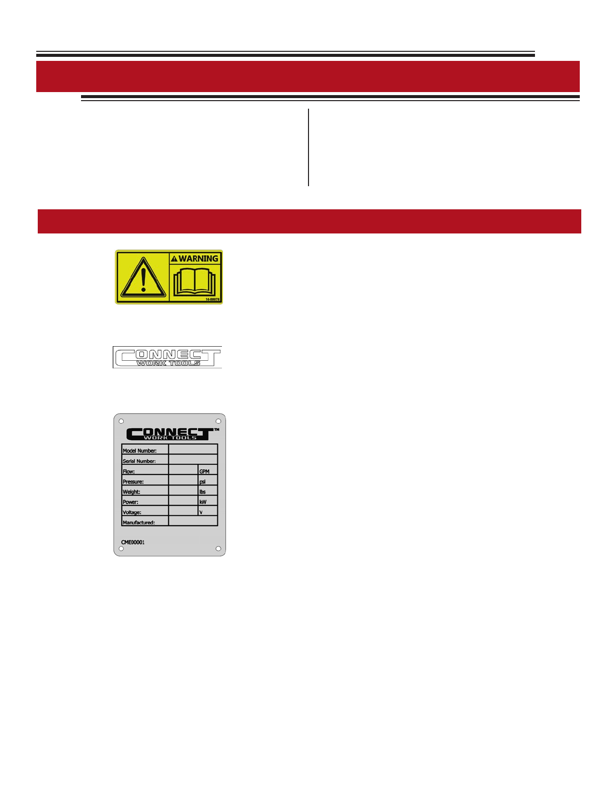
Within this manual, you will nd important safety
information. e information will include specic
information related to the Connect Work Tools attachment
as well as the carrier. It is imperative that operators,
maintenance personnel, or individuals loading or
transporting the equipment read and understand the safety
contents of this manual, as well as all safety decals and
labels. Safety decals and labels must be kept legible and
intact on the attachment. Replace damaged, missing or
illegible safety labels or decals.
Purpose of Safety Messages
e reason safety messages and information has been
included in this manual is most importantly to protect you
and those individuals in the work area. Additionally, it is
provided to eliminate damage to surroundings, attachments
and the carrier due to incorrect operation and use or lack of
maintenance of the equipment.
Key Points before operating equipment
1. Know your surroundings, survey the area prior to
operation.
2. Know where the potential hazards are within the work
area and notify personnel of those hazards.
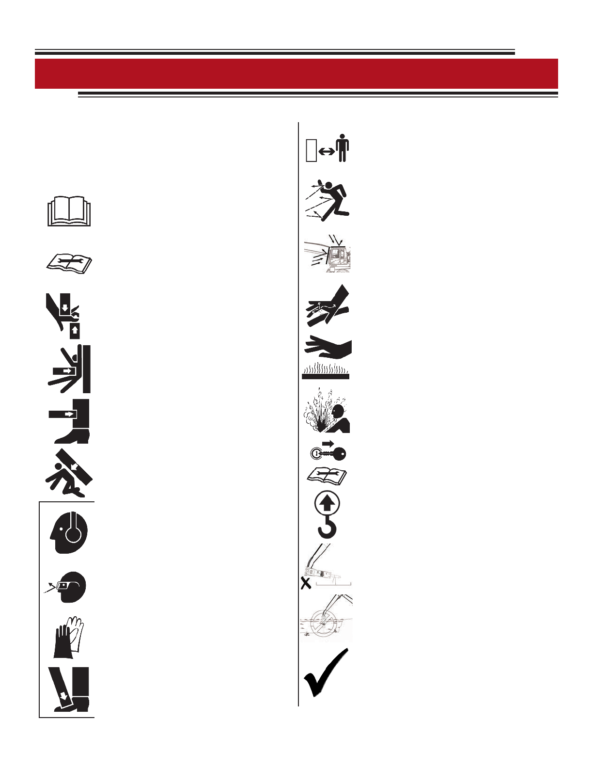
Safety messages provide the following information:
1. Alert personnel to potential hazards
2. Identify the nature of the hazard
3. Describe the severity of the hazard, if
encountered
4. Instruct how to avoid the hazard
ATTENTION, BECOME ALERT, YOUR SAFETY
IS INVOLVED.
Safety symbols and signal words, as shown below, are used
to emphasize all operator, maintenance and repair actions
which, if not strictly followed, could result in a life-
threatening situation, bodily injury or damage to
equipment.
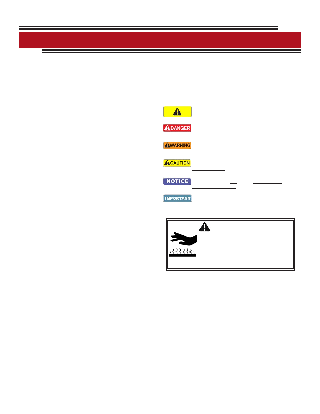
is is the safety alert symbol. It is used to alert you to potential
personal injury hazards. Obey all safety messages that follow
this symbol to avoid possible injury or death.
is safety alert and signal word indicates an imminently
hazardous situation which, if not avoided, will result in death
or serious injury.
is safety alert and signal word indicates a potentially
hazardous situation which, if not avoided, could result in death
or serious injury.
is safety alert and signal word indicates a potentially
hazardous situation which, if not avoided, may result in minor
or moderate injury.
is signal word indicates a potentially hazardous situation
which, if not avoided, may result in property damage or
damage to the equipment.
is signal word indicates a situation which, if not avoided,
may result in damage to the equipment.
Signal Words
CAUTION
Burn injury from contact with hot
surface. Some components of the
Breaker become hot during operation.
Allow parts and uids to cool before
handling.
Fig. SI.2 Safety Message
Signal Words Used for Non-Hazard Messages
is manual contains other message types that use the
signal words IMPORTANT and NOTE. ese are
informational messages that provide instructions and are
not considered hazardous to workers.
IMPORTANT - Identify instructions that if not followed,
may damage the equipment or diminish the service life of
components.
NOTE - Highlight suggestions, which will enhance
installation, reliability, or operation.
Fig. SI.1 Safety Signal Words

Connect Work Tools - www.connectworktools.com - 920.238.6657
3CME00010_release23October
Safety InformationSafety Information
Safety, Information and Identication Labels
Information labels axed to the Connect Work Tools
equipment include safety warnings, identication and
instructions important to operation and service.
Keep all safety & identication labels clean. Words and
illustrations must be legible.
Before operating this equipment, replace damaged or
missing labels. For replacement, refer to the
appropriate Parts Manual for identication.
Fig. Label DescriptionFig. Label Description
Fig. L-2
READ INSTRUCTIONS - Decal directs personnel to the manual for
further information/instructions.
Fig. L-1
Fig. L-3
CONNECT WORK TOOLS LOGO - is decal is the Connect Work
Tools identier and is a registered trademark of Connect Work Tools.
SERIAL PLATE - Contains identifying information about the
equipment, including: Manufacturer's name, Model number, Serial
number, Oil ow, Operating pressure, Product weight, Power, Voltage,
Date manufactured.

CME00010_release23October
Connect Work Tools - www.connectworktools.com - 920.238.6657
4
Safety InformationSafety Information
Meaning of Pictograms
Pictograms are used to rapidly communicate
information. For the purposes of this manual and labels
axed to the Connect Work Tools equipment, pictograms
are dened as follows:
• Read the Manual
• Refer to the manual for further details
• Procedures are explained in the
manual
Read the Service Manual for Additional
Information
• Crush Point
• Pinch Point
Moving part (in direction indicated by
arrow)
• Falling object
• Unsupported loads
Personal Protection Equipment
• Safety Eyewear
Personnel maintain a safe distance from
breaker
Fragments/debris becoming airborne
projectiles
Protective guards required on cab when
operating this work tool
Leaking uid under pressure
Hot Surfaces
• Hearing Protection
• Gloves
• Safety Shoes
• Falling Part
Gas/Oil under pressure
Shut o carrier & remove key before
servicing
Identies li point
Any gure displaying an X-out or a circle
with a diagonal slash is a prohibited
action
Prohibited actions must be avoided to
prevent injury and/or equipment damage
e check mark is used to indicate correct
actions or approved methods that are
recommended
Fig. SI.3 Meaning of Pictograms

Connect Work Tools - www.connectworktools.com - 920.238.6657
5CME00010_release23October
Safety InformationSafety Information
Attention Read the Manual
Improper installation, operation or maintenance of the
Connect Work Tools Equipment could result in serious
injury or death. Only qualied operators may operate the
Connect Work Tools equipment. Personnel responsible
for the maintenance of the Connect Work Tools
equipment or its systems, including inspection,
installation or adjustments must also be qualied.
Operators and personnel responsible for the
maintenance of this equipment should read this manual.
Other manuals, such as those published by the
machinery used in support of the Connect Work Tools
equipment, should also be read.
General Construction Safety
Always follow procedures that promote safe
conditions for workers and bystanders. e standard
safety precautions expected and required of those
working in construction shall include, but not limited to:
• Locating existing underground service and utility
lines
• Establishing pedestrian barriers
• Using personal protection equipment appropriate to
working conditions, etc.
Owner's Responsibilities
Ensure that only qualied personnel operate and service
the Connect Work Tools equipment.
Ensure personal protection equipment is available to
personnel and enforce the use of PPE.
Ensure that carriers are in safe, working order and all
guards and safety equipment is installed and in operating
condition.
Ensure safety-related materials such as instructions and
including this manual are kept in a convenient location
so that they are easily accessible to operators and
maintenance personnel.
Personal Protective Equipment (PPE)
Personnel operating or nearby the equipment and exposed
to the hazard of falling, ying and splashing objects, or
exposed to harmful dusts, fumes, mists, vapors, or gases
shall use the particular personal protective equipment
(PPE) necessary to protect them from the hazard. Such PPE
may include safety eyewear, face shield, hearing protection,
safety footwear, gloves and dust mask. Supervisors shall
review proper PPE selection and ensure PPE is made
available to personnel. Personnel are responsible for
wearing PPE as directed by the supervisor.
Construction equipment designed with guards shall have
guards in place when equipment is in use. Guards are tted
to the equipment to protect against unsafe situations that
could not be eliminated through design measures. Where it
was not possible to prevent an unsafe situation by means of
a guard, safety messages appear on the equipment, warning
personnel of a hazardous condition.
Guards shall not be removed unless for the purpose of
inspection and service of components. All guards must be
reinstalled aer service or adjustments are completed. Do
not operate the Connect Work Tools attachments without
guards.
Additional guarding, not included with the Connect Work
Tools equipment, is necessary at the operator's station to
protect the operator and other nearby personnel against
ying debris from material being cut or demolished. Do not
handle, demolish or cut material overhead without proper
guards installed.
To prevent accidental start up, the control switch shall be
located in a protected area that is guarded and makes it
dicult to accidentally operate the equipment.
Protective Equipment - Guarding

CME00010_release23October
Connect Work Tools - www.connectworktools.com - 920.238.6657
6
Safety InformationSafety Information
Unapproved Modications
In order to provide and maintain ecient production and reliable service, while ensuring operator safety, the Con-
nect Work Tools equipment may not be modied or used for any other purpose other than, for which it was intended.
Use of the Connect Work Tools equipment, other than those specied in this manual, may place personnel at risk
of injury and/or may subject the equipment to damage. e Connect Work Tools equipment shall not be modied
or used in unapproved applications unless written consent is received from the Connect Work Tools Engineering
Department.
Information in this manual is subject to change without advance notice
Contact your Connect Work Tools Representative or the Connect Work Tools Parts Department for replacement manuals.
Inquiries regarding the content of this manual must include the release date shown below

Connect Work Tools - www.connectworktools.com - 920.238.6657
7CME00010_release23October
Table of ContentsTable of Contents
Operator's Manual Section
Safety Information . . . . . . . . . . . . . . . . . . . . . . . . . . . . . . . . . . . . . . . . . . . . . . . . . . . . . . . . . . . . . . . . . . . . . . . . . . . . . . . . . . . . . . . . . . 2
Table of Contents . . . . . . . . . . . . . . . . . . . . . . . . . . . . . . . . . . . . . . . . . . . . . . . . . . . . . . . . . . . . . . . . . . . . . . . . . . . . . . . . . . . . . . . . . . . 7
General Information
1. General . . . . . . . . . . . . . . . . . . . . . . . . . . . . . . . . . . . . . . . . . . . . . . . . . . . . . . . . . . . . . . . . . . . . . . . . . . . . . . . . . . . . . . . . . . . . . . . . . .9
1.0 Specications
1.1 Magnet Specications. . . . . . . . . . . . . . . . . . . . . . . . . . . . . . . . . . . . . . . . . . . . . . . . . . . . . . . . . . . . . . . . . . . . . . . . . . . . . . . . . . . . 10
1.1 Magnet Layout . . . . . . . . . . . . . . . . . . . . . . . . . . . . . . . . . . . . . . . . . . . . . . . . . . . . . . . . . . . . . . . . . . . . . . . . . . . . . . . . . . . . . . . . . . 11
2.0 Installation
2.1 Mounting & Dismounting . . . . . . . . . . . . . . . . . . . . . . . . . . . . . . . . . . . . . . . . . . . . . . . . . . . . . . . . . . . . . . . . . . . . . . . . . . . . . . . . .12
3.0 Safety Precautions & Operating Instructions
3.1 Noise. . . . . . . . . . . . . . . . . . . . . . . . . . . . . . . . . . . . . . . . . . . . . . . . . . . . . . . . . . . . . . . . . . . . . . . . . . . . . . . . . . . . . . . . . . . . . . . . . . . 13
3.2 Vibrations . . . . . . . . . . . . . . . . . . . . . . . . . . . . . . . . . . . . . . . . . . . . . . . . . . . . . . . . . . . . . . . . . . . . . . . . . . . . . . . . . . . . . . . . . . . . . . .13
3.3 Electromagnetic Compatibility . . . . . . . . . . . . . . . . . . . . . . . . . . . . . . . . . . . . . . . . . . . . . . . . . . . . . . . . . . . . . . . . . . . . . . . . . . . . .13
3.4 Safety Use . . . . . . . . . . . . . . . . . . . . . . . . . . . . . . . . . . . . . . . . . . . . . . . . . . . . . . . . . . . . . . . . . . . . . . . . . . . . . . . . . . . . . . . . . . . . . . .14
3.5 Operation . . . . . . . . . . . . . . . . . . . . . . . . . . . . . . . . . . . . . . . . . . . . . . . . . . . . . . . . . . . . . . . . . . . . . . . . . . . . . . . . . . . . . . . . . . . . . . .14
4.0 Inspection and Maintenance
4.1 Cleaning the hydraulic magnet . . . . . . . . . . . . . . . . . . . . . . . . . . . . . . . . . . . . . . . . . . . . . . . . . . . . . . . . . . . . . . . . . . . . . . . . . . . . 15
4.2 Routine maintenance . . . . . . . . . . . . . . . . . . . . . . . . . . . . . . . . . . . . . . . . . . . . . . . . . . . . . . . . . . . . . . . . . . . . . . . . . . . . . . . . . . . . .15
4.3 Repairing faults inspection. . . . . . . . . . . . . . . . . . . . . . . . . . . . . . . . . . . . . . . . . . . . . . . . . . . . . . . . . . . . . . . . . . . . . . . . . . . . . . . . 16
4.4 Assembling. . . . . . . . . . . . . . . . . . . . . . . . . . . . . . . . . . . . . . . . . . . . . . . . . . . . . . . . . . . . . . . . . . . . . . . . . . . . . . . . . . . . . . . . . . . . . 16
4.5 Normal Inspection . . . .. . . . . . . . . . . . . . . . . . . . . . . . . . . . . . . . . . . . . . . . . . . . . . . . . . . . . . . . . . . . . . . . . . . . . . . . . . . . . . . . . . . 17
4.6 Maintenance Schedule . . . . . . . . . . . . . . . . . . . . . . . . . . . . . . . . . . . . . . . . . . . . . . . . . . . . . . . . . . . . . . . . . . . . . . . . . . . . . . . . . . . .17
5.0 Hydraulic Circuit
5.1 Hydraulic Hydraulic Circuit . . . . . . . . . . . . . . . . . . . . . . . . . . . . . . . . . . . . . . . . . . . . . . . . . . . . . . . . . . . . . . . . . . . . . . . . . . . . . . . 18
6.0 Troubleshooting
6.1 Troubleshooting . . . . . . . . . . . . . . . . . . . . . . . . . . . . . . . . . . . . . . . . . . . . . . . . . . . . . . . . . . . . . . . . . . . . . . . . . . . . . . . . . . . . . . . . .19
Parts Manual Section
Equipment Identication
Equipment Identication . . . . . . . . . . . . . . . . . . . . . . . . . . . . . . . . . . . . . . . . . . . . . . . . . . . . . . . . . . . . . . . . . . . . . . . . . . . . . . . . . . . .21
CM Magnet
CM38 - Magnet Assembly . . . . . . . . . . . . . . . . . . . . . . . . . . . . . . . . . . . . . . . . . . . . . . . . . . . . . . . . . . . . . . . . . . . . . . . . . . . . . . . . . . . .22
CM42 & CM46 - Hydraulic Generator Set . . . . . . . . . . . . . . . . . . . . . . . . . . . . . . . . . . . . . . . . . . . . . . . . . . . . . . . . . . . . . . . . . . . . . .23
CM42 & CM50 - Magnet Assembly . . . . . . . . . . . . . . . . . . . . . . . . . . . . . . . . . . . . . . . . . . . . . . . . . . . . . . . . . . . . . . . . . . . . . . . . . . . 27
CM50 - Hydraulic Generator Set . . . . . . . . . . . . . . . . . . . . . . . . . . . . . . . . . . . . . . . . . . . . . . . . . . . . . . . . . . . . . . . . . . . . . . . . . . . . . . 28
Warranty
Warranty Form (D-0363). . . . . . . . . . . . . . . . . . . . . . . . . . . . . . . . . . . . . . . . . . . . . . . . . . . . . . . . . . . . . . . . . . . . . . . . . . . . . . . . . . . . .32

CME00010_release23October
Connect Work Tools - www.connectworktools.com - 920.238.6657
8
Information in this manual is subject to change without advance notice
List of FiguresList of Figures
Operator's Manual Figures
Safety Information
Fig SI.1 Safety Signal Words . . . . . . . . . . . . . . . . . . . . . . . . . . . . . . . . . . . . . . . . . . . . . . . . . . . . . . . . . . . . . . . . . . . . . . . . . . . . . . . . . . .2
Fig SI.2 Safety Message . . . . . . . . . . . . . . . . . . . . . . . . . . . . . . . . . . . . . . . . . . . . . . . . . . . . . . . . . . . . . . . . . . . . . . . . . . . . . . . . . . . . . . .2
Fig L1-L3 Labels . . . . . . . . . . . . . . . . . . . . . . . . . . . . . . . . . . . . . . . . . . . . . . . . . . . . . . . . . . . . . . . . . . . . . . . . . . . . . . . . . . . . . . . . . . . . 3
Fig.SI.3 Meaning of Pictograms . . . . . . . . . . . . . . . . . . . . . . . . . . . . . . . . . . . . . . . . . . . . . . . . . . . . . . . . . . . . . . . . . . . . . . . . . . . . . . . 4
1.0 Specications
Fig.1.1 Magnet Specications . . .. . . . . . . . . . . . . . . . . . . . . . . . . . . . . . . . . . . . . . . . . . . . . . . . . . . . . . . . . . . . . . . . . . . . . . . . . . . . . . 10
Fig 1.2 Magnet Layouts . . . . . . . . . . . . . . . . . . . . . . . . . . . . . . . . . . . . . . . . . . . . . . . . . . . . . . . . . . . . . . . . . . . . . . . . . . . . . . . . . . . . . . .11
4.0 Inspection and Maintenance
4.1 Torque Specications . . . . . . . . . . . . . . . . . . . . . . . . . . . . . . . . . . . . . . . . . . . . . . . . . . . . . . . . . . . . . . . . . . . . . . . . . . . . . . . . . . . . . 16
4.2 Maintenance Schedule. . . . . . . . . . . . . . . . . . . . . . . . . . . . . . . . . . . . . . . . . . . . . . . . . . . . . . . . . . . . . . . . . . . . . . . . . . . . . . . . . . . . .17
5.0 Hydraulic Circuit
5.1 Hydraulic Magnetic Circuit . . . . . . . . . . . . . . . . . . . . . . . . . . . . . . . . . . . . . . . . . . . . . . . . . . . . . . . . . . . . . . . . . . . . . . . . . . . . . . . .18
6.0 Trouble Shooting
6.1 Troubleshooting Chart . . . . . . . . . . . . . . . . . . . . . . . . . . . . . . . . . . . . . . . . . . . . . . . . . . . . . . . . . . . . . . . . . . . . . . . . . . . . . . . . . . . 19
Contact your Connect Work Tools Representative or the Connect Work Tools Parts Department for replacement manuals.
Inquiries regarding the content of this manual must include the release date shown below

Connect Work Tools - www.connectworktools.com - 920.238.6657
9CME00010_release23October
General InformationGeneral Information
1. Introduction
Preface
is manual will provide an understanding of the Connect Work Tools Magnet by providing instructions for safe and
eective operation and instructions for regular maintenance activities of the magnet in addition to parts information.
Before installation or operation of the magnet for the rst time, please read and understand this manual.
e specications and designs presented in this manual are subject to change without prior notice.
2. Safety Precautions
Operation
• Operate the magnet for its intended purpose only.
• Operate the magnet only when the operator is seated in the cabin with full control of the machine.
• No bystanders are allowed in the vicinity of the magnet when it is operating. Debris can cause serious injury to by-
standers.
• Stay clear of the compactor when it is operating.
• Before operating the magnet, read and follow the safety decals located on equipment.
• Be sure that all decals are clearly visible. Clean and replace as necessary.
Protective Equipment
• Always wear the following personal protective equipment: safety glasses, ear protection, protective gloves and
protective shoes.
Heat Caution
• Never touch the hot parts. Wait for them to cool down rst if you have to touch them.
• Hot hydraulic oil can cause burns. Never use your ngers to check for hydraulic uid leaks and always keep your face
away from a possible leak.

CME00010_release23October
Connect Work Tools - www.connectworktools.com - 920.238.6657
10
1.0 Specications1.0 Specications
1.1 Magnet Specications
* e above technical specication can be changed without prior notice.
Models Units CM38ID CM42ID CM46ID CM50ID CM60ID
Machine Weight
US Ton/ (kg)
min.
15 (14,000) 17 (15,422) 20 (18,144) 24 (21,772) 32 (29,030)
Machine Weight
US Ton (kg)
max.
22 (20,000) 25 (22,680) 28 (25,401) 35 (31,751) 45 (40,823)
Min. Flow GPM
(liters/min)
GPM
(liters/min)
16 (60) 19 (72) 22 (83) 27 (102) 32 (121)
Max. Flow GPM
(liters/min)
GPM
(liters/min)
34 (130) 37 (140) 37 (140) 40 (151) 40 (151)
Diameter Inches (mm) 38 (960) 42 (1,067) 46 (1,168) 50 (1,270) 60 (1,524)
H base Inches (mm) 10 (260) 10 (254) 11 (279) 11 (279) 12 (305)
H including Chain
& Plate
Inches (mm) 29.5 (850) 32 (813) 32 (813) 32 (813) 32 (813)
Power (kW) kW 4.5 5.5 67.5 12
Weight lbs (kg) 2650 (1200) 3,197 (1,450) 3,417 (1,550) 4,079 (1,850) 6,393 (2,900)
Voltage (V) 220 220 220 220 220
CM Series Magnets
Fig. SI.3 Magnet Specications

Connect Work Tools - www.connectworktools.com - 920.238.6657
11 CME00010_release23October
1.0 Specications1.0 Specications
1.0. Magnet Layout
☑☑Well-designed and robust structure
☑☑Excellent durability by use of high-tensile steel
☑☑Excellent magnetics
☑☑High performance
☑☑Easy mounting and dismounting
1.3. Characteristics
Fig 1.2 Magnet Layout

CME00010_release23October
Connect Work Tools - www.connectworktools.com - 920.238.6657
12
2.1. Mounting and Dismounting
2.0 Installation2.0 Installation
1. Verify machine specications for correct CM series magnet model.1. Verify machine specications for correct CM series magnet model.
2. Mount the bracket using proper torque specications, pin magnet to machine.2. Mount the bracket using proper torque specications, pin magnet to machine.
3. Use hoses equal to or greater than -12 with a minimum pressure rating of 3000 psi (200 bar).3. Use hoses equal to or greater than -12 with a minimum pressure rating of 3000 psi (200 bar).
4. Add the test circuit.4. Add the test circuit.
a. Connect the input pressure line to a ow meter and regulator. Connect the return line to the other sidea. Connect the input pressure line to a ow meter and regulator. Connect the return line to the other side
of the ow regulator.of the ow regulator.
b. Verify machine ow output. Minimum to maximum ow range from 15-40 GPM (57-151 lpm)b. Verify machine ow output. Minimum to maximum ow range from 15-40 GPM (57-151 lpm)
depending on CM magnet series model. Check ow range on serial number tag.depending on CM magnet series model. Check ow range on serial number tag.
5. Once the necessary ow is achieved, add hydraulic the jump lines to pressure line (P) and the return line (T).5. Once the necessary ow is achieved, add hydraulic the jump lines to pressure line (P) and the return line (T).
If hoses are inverted, an internal control valve will prevent ow to the generator.If hoses are inverted, an internal control valve will prevent ow to the generator.
6. Remove the magnet inspection window. is will reveal the voltage reading from the generator.6. Remove the magnet inspection window. is will reveal the voltage reading from the generator.
7. Energize the magnet.7. Energize the magnet.
a. CM series magnets run o constant ow with variable pressure. During operation, constant owa. CM series magnets run o constant ow with variable pressure. During operation, constant ow
maintains the magnetic eld.maintains the magnetic eld.
b. Voltage should range from 200-240 V.b. Voltage should range from 200-240 V.
c. A set of 4 to 7 capacitors will discharge energy when ow is stopped.c. A set of 4 to 7 capacitors will discharge energy when ow is stopped.
8. If voltage parameter is not met, verify machine circuit.8. If voltage parameter is not met, verify machine circuit.
a. Try alternative and summation pumps if voltage drops lower when travel and cylinder systems area. Try alternative and summation pumps if voltage drops lower when travel and cylinder systems are
used.used.
b. Use troubleshooting procedure if the voltage is above or below the prescriped threshold.b. Use troubleshooting procedure if the voltage is above or below the prescriped threshold.
9. Reinstall inspection window, following safety precautions during operation.9. Reinstall inspection window, following safety precautions during operation.

Connect Work Tools - www.connectworktools.com - 920.238.6657
13 CME00010_release23October
Safety Precautions
Do not perform inspection or maintenance work when the engine of the carrier vehicle is running. It is required
that there be two qualied personnel to perform inspections. One of the personnel will operate the vehicle, and
the other person to check the operation of the magnet. During this inspection, do not touch the magnet or allow
any part of the body or clothing come into contact with it.
3.0 Safety Precautions & Operating Instructions3.0 Safety Precautions & Operating Instructions
3.1 Noise:3.1 Noise:
e noise produced by the hydraulic magnet generator is 90dB measured at 3 (1 meter) from the magnet.e noise produced by the hydraulic magnet generator is 90dB measured at 3 (1 meter) from the magnet.
Anyone approaching the hydraulic magnet in operation for maintenance purposes must utilize suitable hearingAnyone approaching the hydraulic magnet in operation for maintenance purposes must utilize suitable hearing
protection. Under normal operating conditions, it is forbidden to come within 66 (20 meters) of the hydraulicprotection. Under normal operating conditions, it is forbidden to come within 66 (20 meters) of the hydraulic
magnet.magnet.
3.2 Vibrations:3.2 Vibrations:
e hydraulic generator generates minimal vibrations, normally acceptable on excavators where it is mounted.e hydraulic generator generates minimal vibrations, normally acceptable on excavators where it is mounted.
3.3 Electromagnetical Compatibility - Eects on Workers3.3 Electromagnetical Compatibility - Eects on Workers
e hydraulic magnet is a powerful magnetic eld generator. e intensity of the magnetic eld it generates de-e hydraulic magnet is a powerful magnetic eld generator. e intensity of the magnetic eld it generates de-
creases with the distance from the magnet and at a distance of 6 (2 meters), it is not dangerous for personnel.creases with the distance from the magnet and at a distance of 6 (2 meters), it is not dangerous for personnel.
However, to avoid dangerous consequences you must:However, to avoid dangerous consequences you must:
• avoid approaching the magnet with ferromagnetic objects in your hands, as they may be attracted and cause• avoid approaching the magnet with ferromagnetic objects in your hands, as they may be attracted and cause
crushing;crushing;
• avoid approaching the magnet with electrical or electronic safety devices, measuring instruments and watches• avoid approaching the magnet with electrical or electronic safety devices, measuring instruments and watches
as they may be disturbed and/or magnetized;as they may be disturbed and/or magnetized;
• keep computers, monitors, credit cards, records, audio and videotapes, magnetic cards, etc. at a safe distance a• keep computers, monitors, credit cards, records, audio and videotapes, magnetic cards, etc. at a safe distance a
minimum of 6 (2m).minimum of 6 (2m).
e personnel in charge must point out the danger to uninformed personnel who may inadvertently approache personnel in charge must point out the danger to uninformed personnel who may inadvertently approach
the site.the site.
It is strictly forbidden for people who are sensitive to magnetic elds (people with pace-It is strictly forbidden for people who are sensitive to magnetic elds (people with pace-
makers, active or passive implants, metal prostheses, pregnant women, etc.) to approach themakers, active or passive implants, metal prostheses, pregnant women, etc.) to approach the
operating hydraulic magnet at a distance of less than at a distance of less than 6 (2 meters).operating hydraulic magnet at a distance of less than at a distance of less than 6 (2 meters).
Warning signs indicating that there is danger of magnetic elds must be placed at a suitableWarning signs indicating that there is danger of magnetic elds must be placed at a suitable
distance to warn all operators and non-operators of the dangers of the magnetic elds.distance to warn all operators and non-operators of the dangers of the magnetic elds.

CME00010_release23October
Connect Work Tools - www.connectworktools.com - 920.238.6657
14
3.0 Safety Precautions & Operating Instructions3.0 Safety Precautions & Operating Instructions
Do not use the magnet to crush objects, this could cause damage to the equipment
3.5 Operation
a) Be aware of any object which could be dangerous during operation.
b) Verify the oil ow and if necessary, adjust the ow control valve.
c) Open the stop valve on the excavator's arm.
d) Run the magnet before operation until the oil temperature reaches 120°-175°F (50oC~80oC).
e) During operation, do not apply too much down pressure with the boom.
3.4 Safe Use:3.4 Safe Use:
3.4.1 Conditions of the Operators3.4.1 Conditions of the Operators
Operators must be t for work and psychological and physical capabilities of attending to the requirements ofOperators must be t for work and psychological and physical capabilities of attending to the requirements of
magnetic related activities during all phases of operation. e operator assigned to the magnet must positionmagnetic related activities during all phases of operation. e operator assigned to the magnet must position
themselves in a way that does not pose a risk to their own safety when carrying out maintenance work, antici-themselves in a way that does not pose a risk to their own safety when carrying out maintenance work, antici-
pating and avoiding possible dangerous movements.pating and avoiding possible dangerous movements.
If it is necessary to change any damaged parts, replace them only with original Connect Work Tools genuine
spares.
When installing bolts, rst check and clean them.
Coat the threaded area with Loctite Red 271 and tighten them according to the bolt torque table in section
4.4.
☑☑
☑☑
☑☑
☑☑

Connect Work Tools - www.connectworktools.com - 920.238.6657
15 CME00010_release23October
4.0 Inspection and Maintenance4.0 Inspection and Maintenance
4.1 Cleaning the hydraulic magnet4.1 Cleaning the hydraulic magnet
* Cleaning can be done using the means, equipment and detergents commonly used for general cleaning of in-* Cleaning can be done using the means, equipment and detergents commonly used for general cleaning of in-
dustrial equipment (avoiding the use of acidic substances, solvents or aggressive detergents such as caustic soda).dustrial equipment (avoiding the use of acidic substances, solvents or aggressive detergents such as caustic soda).
* Clean by removing foreign substances and soiling with vacuum cleaners, absorbent cloths, etc.* Clean by removing foreign substances and soiling with vacuum cleaners, absorbent cloths, etc.
* Do not use water jets to clean the electromagnet.* Do not use water jets to clean the electromagnet.
4.2 Routine Maintenance4.2 Routine Maintenance
Routine maintenance operations are fairly limited but must be carried out by qualied personnel.Routine maintenance operations are fairly limited but must be carried out by qualied personnel.
Every 100 working hours it is necessary to:Every 100 working hours it is necessary to:
☑☑ Check the integrity of the welds on the magnet body and the cover; if cracks are found, contact theCheck the integrity of the welds on the magnet body and the cover; if cracks are found, contact the
manufacturer.manufacturer.
☑☑ Check the integrity and correct tightening of the screws that secure the bell to the magnetic base; ifCheck the integrity and correct tightening of the screws that secure the bell to the magnetic base; if
they are loose, retighten them correctly.they are loose, retighten them correctly.
☑☑ Check the integrity of the chains or other means of attachment of the hydraulic magnet to theCheck the integrity of the chains or other means of attachment of the hydraulic magnet to the
excavator; if signs of wear are found, it is necessary to replace these means of attachmentexcavator; if signs of wear are found, it is necessary to replace these means of attachment
☑☑ Check to make sure that the safety stickers are present; if they are missing/damaged they must beCheck to make sure that the safety stickers are present; if they are missing/damaged they must be
replaced; make sure that the identication plate is present and readable; if it is lost/unreadable, contactreplaced; make sure that the identication plate is present and readable; if it is lost/unreadable, contact
the manufacturer;the manufacturer;
Every 1000 working hours it is necessary:Every 1000 working hours it is necessary:
☑☑ Aer ensuringAer ensuring that at least 30 minutes have elapsedthat at least 30 minutes have elapsed since the last demagnetization command,since the last demagnetization command,
remove the cover by unscrewing the sealing screws and the connection tubes.remove the cover by unscrewing the sealing screws and the connection tubes.
☑☑ en check that the interior is clean and that all generator unit screws are tightened correctly. Ifen check that the interior is clean and that all generator unit screws are tightened correctly. If
necessary, clean the components of the generator block and tighten the screws.necessary, clean the components of the generator block and tighten the screws. Do not dismantle theDo not dismantle the
electronics block!electronics block!
☑☑ Re-assemble the cover by xing it with the screws, which must be tightened with a torque spannerRe-assemble the cover by xing it with the screws, which must be tightened with a torque spanner
with the appropriate torque, and connect the connection tubes.with the appropriate torque, and connect the connection tubes.
* Cleaning must be carried out by specialized personnel and is periodically necessary to free the structure, mech-* Cleaning must be carried out by specialized personnel and is periodically necessary to free the structure, mech-
anisms, command and control devices from accumulations of dust or dirt.anisms, command and control devices from accumulations of dust or dirt.

CME00010_release23October
Connect Work Tools - www.connectworktools.com - 920.238.6657
16
Fig 4.1 Torque Specications
4.0 Inspection and Maintenance4.0 Inspection and Maintenance
4.4 Assembling
Metric Fasteners
Fastener Property Class 10.9 12.9 10.9 12.9 10.9 12.9
Thread Treatment Dry Loctite 242 or 271 Anti-Seize
Basic Major Dia. (mm) Thread Pitch (mm/thread) Torque (Ft*Lbf) Torque (Ft*Lbf) Torque (Ft*Lbf)
10 1.5 53 62 61 72 40 47
12 1.75 93 109 107 125 70 81
14 2 148 173 170 199 111 130
16 2 231 270 265 310 173 202
20 2.5 450 526 517 605 337 394
22 2.5 612 715 704 823 459 537
24 3 778 909 895 1,046 583 682
27 3 1,138 1,330 1,309 1,530 854 998
30 3.5 1,546 1,806 1,777 2,077 1,159 1,355
4.3 Repairing Faults Inspection
In the event of a failure or malfunction of the hydraulic magnet, the user can carry out a pre-diagnosis of theIn the event of a failure or malfunction of the hydraulic magnet, the user can carry out a pre-diagnosis of the
failure by following the trouble shooting chart on Illustration 4.6. e troubleshooter should enter the diagramfailure by following the trouble shooting chart on Illustration 4.6. e troubleshooter should enter the diagram
at the point that corresponds to the (abnormal) behaviour of the magnet and cascade downwards by performingat the point that corresponds to the (abnormal) behaviour of the magnet and cascade downwards by performing
the indicated actions or answering the indicated questions, and then moving further down along the diagramthe indicated actions or answering the indicated questions, and then moving further down along the diagram
according to said response. In some cases, actions or measurements will have to be performed before the answeraccording to said response. In some cases, actions or measurements will have to be performed before the answer
can be given.can be given.
If the pre-diagnosis performed does not enable the possible cause of the failure to be identied, the user shouldIf the pre-diagnosis performed does not enable the possible cause of the failure to be identied, the user should
contact Connect Work Tools for further technical assistance. e user should also contact the Connect Workcontact Connect Work Tools for further technical assistance. e user should also contact the Connect Work
Tools when the troubleshooting procedure leads to the identication of a failure that cannot be immediately andTools when the troubleshooting procedure leads to the identication of a failure that cannot be immediately and
easily repaired.easily repaired.
In all cases where the user contacts the manufacturer (or its local dealer), the user must have the following infor-In all cases where the user contacts the manufacturer (or its local dealer), the user must have the following infor-
mation available:mation available:
a.) Model of hydraulic magneta.) Model of hydraulic magnet
b.) Serial numberb.) Serial number
c.) Make and model of the excavator on which the magnet is installedc.) Make and model of the excavator on which the magnet is installed
d.) A detailed description of the issue or anomalyd.) A detailed description of the issue or anomaly
e.) Any other useful informatione.) Any other useful information
Connect Work Tools will give instructions on how to proceed or will prepare to intervene.Connect Work Tools will give instructions on how to proceed or will prepare to intervene.

Connect Work Tools - www.connectworktools.com - 920.238.6657
17 CME00010_release23October
4.6 Maintenance Schedule
4.5 Normal Inspection
☑☑ Before operating the magnet, read the contents and safety information contained in this manual
☑☑ Check for oil leakage in the hydraulic lines and change any damaged or faulty parts
☑☑ Check the condition of mounting bracket and pins
☑☑ Check the structure for cracks. If welding is necessary, please check with the manufacturer before starting
☑☑ Before operation, check the oil levels in the housing
4.0 Inspection and Maintenance4.0 Inspection and Maintenance
Fig 4.6 Maintenance Schedule
Check the hydraulic lines for leaks.
Tighten the screw connection to the adapter plate.
Check the connection to the carrier (bolts, lock pins).
Check the rubber isolators for cracks.
Check the screw connections and tighten as required
Check the oil quantity in the housing.
Check the housings and the adapter plate for cracks.
Clean the unit.
Replace any or all damaged hoses.
Check the adapter plate bolts for wear.
Once a year Change the oil in the housing.
Daily
Weekly
If Necessary
Maintenance Schedule
☑☑
☑☑
☑☑
☑☑
☑☑
☑☑
☑☑
☑☑
☑☑
☑☑
☑☑

CME00010_release23October
Connect Work Tools - www.connectworktools.com - 920.238.6657
18
5.0 Magnet Hydraulic Circuit5.0 Magnet Hydraulic Circuit
5.1 Magnetic Hydraulic Circuit
Fig. 5.1 Magnetic Hydraulic Circuit
This manual suits for next models
5
Table of contents