CONNECTRIC Motrona GV 460 User manual

control – motion – interface
motrona GmbH
Zwischen den Wegen 32
78239 Rielasingen - Germany
Tel. +49 (0)7731-9332-0
Fax +49 (0)7731-9332-30
www.motrona.com
GV48002a_e.doc / Mrz-11 Page 1 / 14
GV 460 / GV 461
Impulse Splitters for Incremental Encoders with
Potential Separation between Input and Outputs
GV 480 / GV 481
Impulse Splitters for Incremental Encoders
with all-around Potential Separation of all Circuits
Figure: GV 460 and GV 480:
Splitters with 8 Output Channels
Figure: GV 461 and GV 481:
Splitters with 4 Output Channels
Operating Instructions

GV48002a_e.doc / Mrz-11 Page 2 / 14
Safety Instructions
•This manual is an essential part of the unit and contains important hints about
function, correct handling and commissioning. Non-observance can result in
damage to the unit or the machine, or even in injury to persons using the
equipment !
•The unit must only be installed, connected and activated by a qualified electrician
•It is a must to observe all general and also all country-specific and application-
specific safety standards
•When this unit is used with applications where failure or maloperation could cause
damage to a machine or hazard to the operating staff, it is indispensable to meet
effective precautions in order to avoid such consequences
•Regarding installation, wiring, environmental conditions, screening of cables and
earthing, you must follow the general standards of industrial automation industry
•- Errors and omissions excepted –
Version: Description
GV48001a/Jan09/af_hk Original edition
GV48002a/Jan09/af_hk Supplements for model GV460

GV48002a_e.doc / Mrz-11 Page 3 / 14
Table of Contents
1. Introduction and Block Diagram 5
2. Electrical Connections and LED Function 8
2.1. Power Supply and LEDs 8
2.2. Auxiliary Encoder Supply 8
2.3. Impulse Inputs 9
2.3.1. Encoders with differential output
(valid for output levels TTL/ 5 volts and for HTL / 10-30 volts as well) 9
2.3.2. Encoders with single-ended output, without inverted signals
(acceptable only with HTL level 10 - 30 volts) 9
2.3.3. Differential signals from an encoder simulation
(TTL level with remarkable noise) 9
2.3.4. Differential signals for encoder channels A and B,
but single-ended marker pulse from proximity switch or photocell 10
2.4. The Outputs 11
2.5. Cascading of Several Units and Encoder Select Function 11
3. Technical Specifications 13
4. Dimensions 14

GV48002a_e.doc / Mrz-11 Page 4 / 14

GV48002a_e.doc / Mrz-11 Page 5 / 14
1. Introduction and Block Diagram
GV460, GV461, GV480 and GV481 represent a series of incremental encoder splitters with a
most compact, space-saving design and with most versatile technical features. All models are
fully identical except for the number of output channels (4 or 8 channels) and the system of
potential separation.
Models GV460 and GV461 are lower in price but provide only a 2-circuit potential separation
between the input on one side and the outputs with power supply on the other side.
Models GV480 and GV481 provide total galvanic separation between inputs, the power supply
and all outputs one against each other. This feature, in general, can be most advantageous
with impulse distribution among expanded production lines with adverse conditions of
EMC / grounding / potential shift etc.
The encoder input is switch-selectable for operation with either standard RS422 signals, with
differential TTL or HTL signals or with single-ended HTL encoder signals. All encoder outputs
provide fully isolated push-pull drivers with individual assignment of the output level for each
of the output channels.
Separate cascading ports provide easy cascading of multiple units without loss of regular
encoder outputs. Furthermore, cascaded units allow selection and commutation between
different encoder inputs.
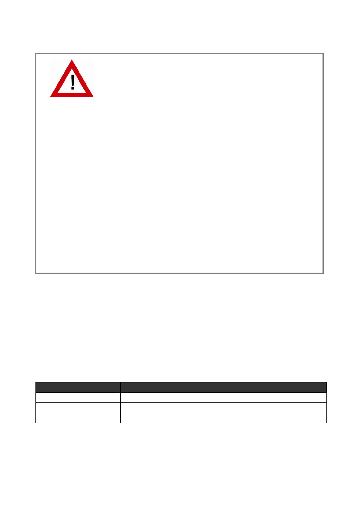
The adjoining block diagrams clearly explain the principle of operation and the potential
conditions between all circuits. For simplification the illustrations show only two of the outputs,
since all other outputs are fully identical.
All units of this series provide an extended range of ambient temperatures for use under
difficult environmental conditions (see Technical Specifications)

GV48002a_e.doc / Mrz-11 Page 6 / 14
12345678
12345678
A/AB/B
Z
/
Z
123
-
+
Power
12345678
GND
Stab
+5,5V
8
2
5
3
1
+V
ref
4 67
GNDIN
A
/
A
B
/
B
Z
/
Z
+VCC
+VCCIN
12345678
GND
0 V
+Lev.
0 V
+Lev.
GND
Select
CASC in
CASC out
GND
ABZ
A
/
A
B
/
B
Z
/
Z
Sel=Lo
Sel=Hi
3
1
5
7
B
Z
A
3
1
5
B
Z
A
7
A
B
Z
A
B
Z
+VCC
GND
+VCC
+VCC = 5,5 V
Block Diagram GV 460 and GV 461

GV48002a_e.doc / Mrz-11 Page 7 / 14
12345678
12345678
A/AB/B
Z
/
Z
123
-
+
Power
12345678
GND
Stab
+5,5V
8
2
5
3
1
+V
ref
4 67
GNDIN
A
/
A
B
/
B
Z
/
Z
+VCC
+VCCIN
12345678
GNDO1
VCCO1
0 V
+Lev.
GNDO2
VCCO2
0 V
+Lev.
GND
Select
CASC in
CASC out
GND
ABZ
A
/
A
B
/
B
Z
/
Z
Sel=Lo
Sel=Hi
3
1
5
7
B
Z
A
3
1
5
B
Z
A
7
A
B
Z
A
B
Z
Block Diagram GV 480 and GV 481

GV48002a_e.doc / Mrz-11 Page 8 / 14
2. Electrical Connections and LED Function
2.1. Power Supply and LEDs
The unit provides a 3-position screw terminal strip for supply from a 10 – 30 volts DC power
unit. The current consumption is approx. 40 mA (no-load operation).
The “Select” input terminal provides selection of the desired source encoder. Details will be
described later.
-+
Select
ON
A
B
Z
The upper LED (green) signals that power is applied to the unit.
The lower LEDs (yellow, red, orange) signal the actual logical states of the input channels A, B
and Z. With very low input frequencies it is possible to visually check the input pulses, the
phase displacement A/B and the index pulse function of an encoder.
2.2. Auxiliary Encoder Supply
The input encoder must be connected to the 8-position input terminal strip.
Depending on the application and the encoder type, one of the following options will apply for
the power supply of the encoder:
a) Remote supply via separate source
b) Same power source that also supplies the GV480 unit (10 - 30 VDC)
c) Use of the built-in auxiliary 5.5 volts power supply (terminal 2 of the input connector)
•When the built-in 5,5 volts power should be used to supply the encoder,
position 8 of the DIL switch has to be set to "ON".
•This action will suspend the galvanic separation between input and the unit
power supply.
•With models GV480 and GV481, also in this case full isolation to all outputs
will be maintained

GV48002a_e.doc / Mrz-11 Page 9 / 14
2.3. Impulse Inputs
The 8-position DIL switch on the front side provides setting of the desired signal formats and
levels. These settings are separately for each of the channels A / B / Z (see block diagram).
For simplification, a short form of the four most common applications is shown below, with the
encoder supply omitted:
2.3.1. Encoders with differential output
(valid for output levels TTL/ 5 volts and for HTL / 10-30 volts as well)
Terminal Connections DIL Switch Setting
A
/A B/B Z/Z
0V
1 2 3 4 5 6 7 8
ON
A
B Z
2.3.2. Encoders with single-ended output, without inverted signals
(acceptable only with HTL level 10 - 30 volts)
Terminal Connections DIL Switch Setting
A
BZ
0V
1 2 3 4 5 6 7 8
ON
2.3.3. Differential signals from an encoder simulation
(TTL level with remarkable noise)
Basically, signals generated by the encoder simulation of a drive can be treated similarly to a
TTL encoder as described under 2.3.1. If however there should come up problems with the
quality of the output signals (caused by awkward environmental conditions), the following
mode of connection may remarkably improve the situation. This is a pure differential operation
with fully floating potential, without any reference point.
It is important to leave terminal 1 unconnected.
Terminal Connections DIL Switch Setting
A
/A B/B Z/Z
1 2 3 4 5 6 7 8
ON

GV48002a_e.doc / Mrz-11 Page 10 / 14
2.3.4. Differential signals for encoder channels A and B,
but single-ended marker pulse from proximity switch or photocell
Besides the most common standard configurations shown before, the unit allows setting of any
other input configuration (e.g. differential encoder inputs on channels A, /A, B, /B, but single-
ended index signal on input Z (from a proximity switch, photocell or similar)
The block diagram shows which of the DIL switch positions is responsible for each of the
channels. It is easy to figure out other settings from the examples given in this manual.
Terminal Connections DIL Switch Setting
A/A B/B Z
0V
+24 V
Proximity Switch
\___ TTL ___/ HTL
1 2 3 4 5 6 7 8
ON
•The normal encoder input terminal will not accept any single-ended signals
with TTL level, i.e. single-ended signals have to provide HTL level
•Nevertheless, in special cases, the cascading inputs of the unit can be used
to apply single-ended TTL signals (CMOS, Low <0.8 V, High >3.5 V). This
however assumes proper EMC conditions and environment as well as short
cables on the input side.
•The input terminal strip provides a codification to avoid accidental mix-up
with the other connectors of the unit

GV48002a_e.doc / Mrz-11 Page 11 / 14
2.4. The Outputs
All outputs provide the non-inverted and the inverted signals at any time, even when on the
input side the inverted signals are not available.
The potential situation between the outputs and other circuits is clearly explained by the block
diagrams in chapter 1. On terminal 1 (0V) and terminal 2 (+Lev.) a remote voltage has to be
applied to each output stage, which at the same time also determines the signal level on the
corresponding output*). The permitted range is from 5 to 30 volts and the signal swing will be
about 0.7 volts less than the remote voltage applied. All output lines are permanently short-
circuit-proof and the maximum output current is 30 mA per line.
The terminal assignment can be found in the block diagram and is also printed to the front plate
of the unit. All output terminal strips have the same codification, since it is fully unimportant to
which of the outputs a terminal strip is connected (only the external voltage applied to the
"Lev." input of the mating connector is responsible for the output level).
*) With models GV460 and GV461, terminals 2 (+Lev.) of all outputs are already
connected to the internal +5V power supply by diodes. This means, where 5 volts
TTL signals are needed, it is not really necessary to apply any remote voltage to the
(+Lev.) terminal.
With models GV480 and GV481 these diodes are missing, therefore a remote
voltage must be applied at any time to make the outputs work.
2.5. Cascading of Several Units and Encoder Select Function
The unit can be cascaded very easily to any number of output channels, without loss of regular
encoder outputs. For cascading, pins 1, 3, 5 and 7 of the cascading output of the first unit must
be connected to the corresponding pins of the cascading input of the follower unit.
An appropriate ribbon cable connection is available under motrona part # FK470
FK470
Cascading lines use the same common GND potential as the power supply of the unit. This
however does not mean any disadvantage in terms of galvanic isolation etc. since cascading
units are always mounted alongside and are also supplied from the same power source.

GV48002a_e.doc / Mrz-11 Page 12 / 14
Cascaded units allow selection of the active source encoder via the encoder select input on the
3-position power connector (see also block diagram):
LOW (or open): outputs refer to the encoder input of the same unit
HIGH (10 – 30 volts): outputs refer to the encoder input of the preceding unit
It is possible at any time to switch over from one to the other source encoder during operation.
Where only one common encoder is used, the select input of the first unit
remains unconnected. The select inputs of all follower units are advantageously
connected to the +pole of the power supply located next to the select input

GV48002a_e.doc / Mrz-11 Page 13 / 14
3. Technical Specifications
Power supply
: 10 – 30 VDC
Power consumption:
(without encoder supply)
: ca. 40 mA
Aux. encoder supply *) : built-in 5.5 V, 200 mA (short-circuit proof)
Max. frequency
: TTL (differential) and RS422: 500 kHz
(diff. voltage >0,5V)
HTL (10 - 30 V): 200 kHz
Input level with HTL single-ended
(no inverted signal available)
: Low: < 4 V, High: > 10 V
Input level "Select" Input : Low: < 4 V, High: > 10 V
Cascading input : A, B, Z, Pegel 5 V
( CMOS, Low <0.8 V, High >3.5 V )
Outputs
: Push-pull stages 5 – 30 V / 30 mA
(short-circuit-proof)
Propagation delay time : 400 nsec.
Mounting : Standard DIN rail
Weight : approx. 400 g
Temperature range **) : Operation: -20° - +60°C (-04° - +140°F)
Storage: -30° - +75°C (-22° - +167°F)
Conformity and standards
: EMC 2004/108/EC: EN 61000-6-2
EN 61000-6-3
*) Please observe galvanic connection to the power supply
**) Humidity non-condensing

GV48002a_e.doc / Mrz-11 Page 14 / 14
4. Dimensions
72 mm (2.835'')
144mm(5.669'')
60,5 mm (2.382'')
70,0 mm (2.756'')
8 mm (0.315'')
This manual suits for next models
3
Table of contents
Other CONNECTRIC Media Converter manuals