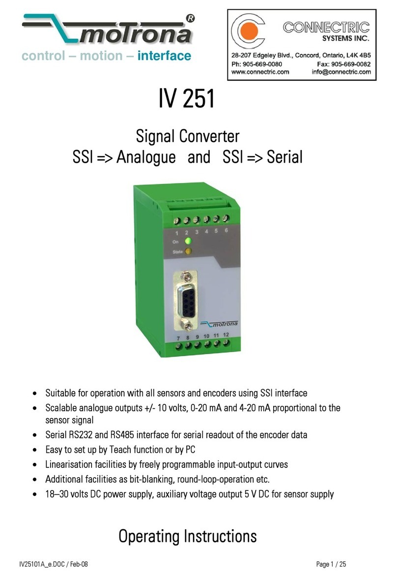
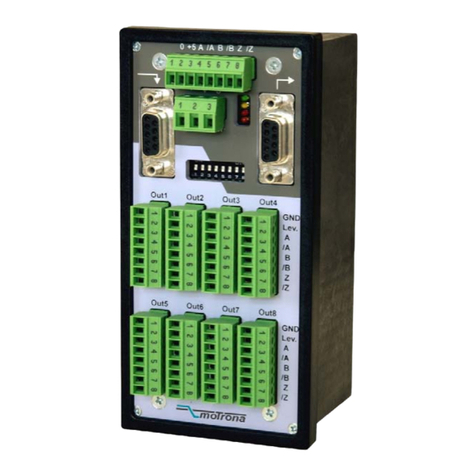
CONNECTRIC moTrona FU 252 User manual

control – motion – interface
motrona GmbH
Zwischen den Wegen 32
78239 Rielasingen - Germany
Tel. +49 (0)7731-9332-0
Fax +49 (0)7731-9332-30
www.motrona.com
FU25202b_e.doc / Dez-08 Page 1 / 34
FU 252
Signal Converter Frequency-to-Analogue
and Frequency-to-Serial
•Input frequency range from 0.1 Hz to 1 MHz for full scale analogue output
•Conversion time only 1 msec. (f > 3 kHz)
•Analogue outputs +/- 10 V, 0 - 20 mA and 4 - 20 mA
•Polarity of analogue signal changes with change of the direction of rotation
•Suitable for conversion of quadrature signals (A/B) as well as single-channel signals,
with all HTL or TTL or RS422 formats and levels
•Suitable for conversion of the sum, the difference or the ratio of two frequencies
•RS 232 and RS 485 interfaces for serial readout of the input frequencies
•Programmable digital filters and programmable linearisation curves
•Easy to set up by simple TEACH procedure, or by PC operator software
Operating Instructions

FU25202b_e.doc / Dez-08 Page 2 / 34
Safety Instructions
•This manual is an essential part of the unit and contains important hints about
function, correct handling and commissioning. Non-observance can result in
damage to the unit or the machine or even in injury to persons using the
equipment!
•The unit must only be installed, connected and activated by a qualified electrician
•It is a must to observe all general and also all country-specific and application-
specific safety standards
•When this unit is used with applications where failure or maloperation could cause
damage to a machine or hazard to the operating staff, it is indispensible to meet
effective precautions in order to avoid such consequences
•Regarding installation, wiring, environmental conditions, screening of cables and
earthing, you must follow the general standards of industrial automation industry
•- Errors and omissions excepted –
Version: Description:
FU25201a_af_hk_04/2007 First edition
FU252021_af_hk_10/2008 Default settings "Frequency Control", "Input Filter", "Analogue Mode"
FU252021_af_hk_10/2008 Commissioning form, completion DIL2 positions 7+8

FU25202b_e.doc / Dez-08 Page 3 / 34
Table of Contents
1. Compatibility Hint ..........................................................................................4
2. Introduction....................................................................................................5
2.1. Impulse input formats and input levels....................................................................5
2.2. Operating range........................................................................................................6
2.3. Suitable encoders and sensors ................................................................................6
3. Terminal Assignments and Connections........................................................7
3.1. Example for use of TTL encoders .............................................................................7
3.2. Example for use of HTL encoders.............................................................................8
3.3. Proximity switches, photocells etc...........................................................................8
3.4. Analogue outputs .....................................................................................................8
3.5. Serial interface.........................................................................................................9
4. DIL Switch Settings......................................................................................10
4.1. Basic mode of operation ........................................................................................10
4.2. Impulse levels and symmetric / asymmetric input formats...................................11
4.3. Analogue output format .........................................................................................12
4.4. Selecting the RS232 or the RS485 serial interface ...............................................13
4.5. Teach function, Test function, loading of default settings....................................13
5. Commissioning.............................................................................................14
5.1. Conversion of one only frequency (single channel or dual channel with direction
signal).....................................................................................................................15
5.2. Conversion and combination of two independent frequencies (A + B, A - B, A x
B, A : B)..................................................................................................................15
6. PC Setup with Use of the Operator Software OS3.x................................... 16
7. Parameter Description .................................................................................18
8. Free Programmable Linearization.................................................................25
9. Monitor Functions........................................................................................ 27
10. Data Readout via Serial Interface................................................................29
11. Dimensions .................................................................................................. 30
12. Specifications ..............................................................................................31
13. Internal Registers and Serial Codes.............................................................32
14. Commissioning Form....................................................................................34

FU25202b_e.doc / Dez-08 Page 4 / 34
1. Compatibility Hint
This product is a successor model of the thousandfold approved converter type FU251. The new
product is suitable for a 100% replacement of the previous model, however some differences
must be observed with DIL switch settings and parameter settings.
Some essential advantages of FU252 compared to FU251 are:
•Maximum frequency 1 MHz (instead of 500 kHz)
•Total conversion time in-out = 1 msec (this was no more assured with FU251 after
the modifications necessary for RoHS conformity)
•Capability to accept even single-ended TTL input signals
(i.e. TTL input A only without inverted TTL signal /A)
•Setting of analogue formats +/-10V, +10V, 0-20 mA and 4-20 mA can be done by
supplementary DIL switch (no more PC required)
•Enhanced auxiliary output 5 V / 250 mA for encoder supply

FU25202b_e.doc / Dez-08 Page 5 / 34
2. Introduction
FU 252 is a small and low-cost, but highly performing converter for industrial applications,
where one frequency or two different frequencies need to be converted into an analogue signal
or a serial data format. The unit has been designed as a compact module with 12 screw
terminals and a 9-position SUB-D connector (female). The housing is suitable for standard DIN
rail mounting.
2.1. Impulse input formats and input levels
The input site provides channels A and B and also the inverted lines /A and /B. All inputs are
designed for use with either HTL level or TTL level, with either single-ended format or
differential format (RS422).
The unit can convert the following formats to analogue and serial:
a. Quadrature signals with a 90°phase displacement. Polarity of the analogue output and sign
of the serial data depend on the direction given by the A/B phase.
b. Single channel impulses on channel A. Input B sets the polarity of the output (LOW =
negative, HIGH = positive). In case of open (unconnected) inputs, please note:
•Open NPN inputs are evaluated as HIGH state
•Open PNP inputs are evaluated as LOW state
Open RS422 inputs may cause problems, therefore please set unused inputs to HTL by
means of the appropriate DIL switch
c. Fully independent frequencies on both channels A and B. The output signal can represent
the sum, the difference, the product or the ratio of the two input frequencies.
A
B
A
B
A
B
A and B, quadrature 90° A=impulse, B=static polarity select A and B: independant frequencies
a. b. c.
+
-

FU25202b_e.doc / Dez-08 Page 6 / 34
2.2. Operating range
The full scale frequency (i.e. the input frequency where the analogue output reaches 10 V or
20 mA) can be set in a range from –1 MHz to +1 MHz. The operating range of the unit can be
assigned to any frequency window inside this frequency range.
A “zero output frequency” can be set to guarantee defined operation of the converter with low
input frequencies.
For applications with unstable input frequencies, the unit provides programmable digital filters
for smoothing of the output signal.
2.3. Suitable encoders and sensors
The FU252 converter can accept the following impulse sources:
•Quadrature encoders with HTL level output (10 – 30 V) and either PNP or NPN or Push-
Pull or NAMUR characteristics, using A and B outputs wit 90° displacement
•Single channel impulse sources like proximity switches or photocells, providing HTL
level at PNP or NPN or Namur characteristics
•TTL / RS422 quadrature encoders with output lines A, /A ,B and /B
•Symmetric single channel sources with TTL / RS422 output, providing differential
signals (e.g. A and /A)
•Asymmetric single channel sources wit TTL level (without inverted signals, e.g. A only)
In general, HTL encoders will be supplied from the same source as the converter itself.
For supply of TTL encoders, the unit provides an auxiliary output of 5.5 volts
(stabilized, max. 250 mA).

FU25202b_e.doc / Dez-08 Page 7 / 34
3. Terminal Assignments and Connections
We recommend connecting the Minus wire of the power supply to earth potential.
Please observe that, under poor earthing and grounding conditions, multiple earth connections
of screens and GND terminals may cause severe problems. In such cases it may be better to
have only one central earthing point for the whole system.
GND terminals 4, 6 and 12 are connected internally.
Under nominal conditions the current consumption of the unit is approx. 70 mA (aux. output
unloaded, see technical specifications) Lower input voltage and load of the aux. output will
increase the consumption accordingly.
123456
7 8 9 101112
Voltage output +/-10V
TTL: input /B HTL: n.c.
TTL: input B HTL: input B
GND ( - ) for analogue signals
Supply +18...30 VDC
(typ. 70 mA)
Current output 0-20mA / 4-20mA
TTL: input /A HTL: n.c.
TTL: input A HTL: input A
Control
Aux. output 5.5V
(max. 250 mA)
GND ( - )
GND ( - )
FU 252
3.1. Example for use of TTL encoders
If applicable, the encoder can be supplied from the FU252 converter. Where the encoder is
already supplied from a remote source, we recommend fully differential operation, with no
GND connection between encoder and converter (see figures a. and b.)
8
9
2
3
11 (+5.5V)
12 (GND)
+
-
TTL encoder FU 252
Screen
A
A
B
B
A
A
B
B
8
9
2
3
11 (+5.5V)
12 (GND)
+
-
Screen
A
A
B
B
A
A
B
B
TTL encoder FU 252

FU25202b_e.doc / Dez-08 Page 8 / 34
3.2. Example for use of HTL encoders
The encoder may be supplied from the same source as the converter, or from another source.
9
3
12 (GND)
GND
HTL encoder FU 252
Screen
+24V
+
A
B
3.3. Proximity switches, photocells etc.
These connections are fully similar to a HTL incremental encoder. With single channel
operation, input B remains unconnected or can be used to select the output polarity. With use
of two independent frequencies for forming sum, difference or ratio, input B is used for the
second input frequency.
To use sensors with 2-wire NAMUR characteristics:
•set the inputs to HTL and NPN
•connect the positive wire of the sensor to the corresponding input and the negative wire
to GND.
3.4. Analogue outputs
The unit provides a +/-10V voltage output and a 0 - 20mA / 4 – 20 mA current output at a
resolution of 14 bits, i.e. the voltage output operates in steps of 1.25 mV and the current output
operates in steps of 2.5 μA.
The nominal load of the voltage output is 2 mA and the current output accepts loads between
zero and 270 ohms.
The analogue ground uses a separate terminal, which however internally is connected to the
GND potential of the power supply.
GND
4
1
7
+/- 10V
20 mA
(R = 0 - 270 ohms)
(Imax = 2 mA)
Screen
Voltage out
Current out

FU25202b_e.doc / Dez-08 Page 9 / 34
3.5. Serial interface
The unit provides a RS232 interface and a RS485 interface, however only one of the two can be
used at a time. Serial communication allows to read out conversion results and to set
parameters and variables by PC, according to need.
54321
9876
GND int.
TxD
RxD
RS232
+5V
T+
T-
R+
R-
RS485 Sub-D-9 (female on unit site)
54321
9876
54321
9876
543 21
9876
543 21
9876
GND
TxD
RxD
PC FU 252
Please connect only pins 2, 3 and 5 !
54321
9876
54321
9876
T+
T-
120 Ohms 120 Ohms
RS485- Bus
( 4- wire )
FU 252
120 Ohms 120 Ohms
R+
R-
T+
T-
R+
R-
54321
9876
54321
9876
T+
T-
120 Ohms 120 Ohms
( 2- wire )
FU 252

FU25202b_e.doc / Dez-08 Page 10 / 34
4. DIL Switch Settings
There is one 8-position switch located on the top side (DIL1), and another 8-position switch is
located on the bottom side of the unit (DIL2). These switches provide major settings of the
desired properties of the unit.
Changes of switch settings will become active only after cycling the power
supply of the unit!
Positions 7 and 8 of switch DIL2 are for internal factory use only and must
both be set to OFF at any time during normal operation
4.1. Basic mode of operation
Positions 2, 3 and 4 of switch DIL1 on the top side allow setting the following operation modes:
12345678
on on on
on on off
on off on
on off off
off on on
off on off
off off on
off off off
Mode of operation
Channel A only
Ratio A : B
Sum A + B
Quadrature A / B / 90°
Channel B only
Product A x B
Difference A - B
A = impulse, B = direction / sign
DIL1
Setting example:
Quadrature input A / B / 90°
Top side
Switch DIL1
Teach button
Bottom side
Switch DIL2

FU25202b_e.doc / Dez-08 Page 11 / 34
4.2. Impulse levels and symmetric / asymmetric input formats
Positions 5 and 7 of DIL1 together with positions 3 to 6 of DIL2 allow setting of all imaginable
combinations of levels and formats.
•All subsequent tables use the following definitions:
„0“ = switch OFF, „1“ = switch ON and
„x“ = position not important
•Switch settings refer to impulse inputs A / B only, but the
Control Input (terminal 10) provides always HTL / PNP format, i.e.
you must apply a positive voltage 10 – 30 volts to activate the
function
•Where you use 2-wire sensors with NAMUR characteristics,
connect the positive pole of the sensor to the corresponding input
terminal, and the negative pole to GND
•Where subsequently you read (A) or (B), this indicates that the
inputs expect asymmetric signals and you will not need the
corresponding inverted signals
•Where however you read (A and /A) or (B and /B), this indicates that
the inputs expect symmetric differential signals according to RS422
standard, i.e. it is mandatory to apply also the inverted signals
4.2.1. Standard settings
If you just use encoders or sensors according to common industrial standards, and if also all
input signals should have the same level, you just can use one of the following three standard
settings and do not need to consider all further alternatives of switch settings.
DIL1 DIL2 Input Characteristics Encoder Type
5 6
7 3 4 5 6
0
0
0
0
0
0
Asymmetric HTL input (A, B),
10 - 30 V level, NPN (switching to -) or
Push-Pull or NAMUR characteristics
Standard HTL encoders,
Proximity switches,
Photo switches etc.
1
0
0
0
0
0
Asymmetric HTL input (A, B),
10 - 30 V level, PNP (switching to +) or
Push-Pull characteristics
PNP Proximity switches,
Photo switches etc.
0
1
0
0
0
0
Symmetric TTL signals or
RS422 signals (A, /A), (B, /B)
(differential, including inverted signal)
Standard TTL encoders
providing A, /A, B, /B
output channels

FU25202b_e.doc / Dez-08 Page 12 / 34
4.2.2. Settings for special applications
Where you find that the standard settings shown before are not suitable for your application,
please go through the following setting options and find out the input levels and characteristics
you need.
DIL1 DIL2 Characteristics of input A Characteristics of input B
5 6
7 3 4 5 6
x
x
0
0
0
1
TTL level (A)
TTL level (B)
x
x
0
0
1
0
HTL level (A and /A)
HTL level (B and /B)
x
x
0
0
1
1
TTL level (A)
TTL level (B and /B)
x
x
0
1
0
0
TTL level (A and /A)
TTL level (B)
x
x
0
1
0
1
HTL level NPN (A)
HTL level PNP (B)
x
x
0
1
1
0
HTL level NPN (A)
TTL level (B and /B)
x
x
0
1
1
1
HTL level NPN (A)
TTL level (B)
x
x
1
0
0
0
HTL level PNP (A)
TTL level (B and /B)
x
x
1
0
0
1
HTL level PNP (A)
TTL level (B)
x
x
1
0
1
0
HTL level PNP (A)
HTL level NPN (B)
x
x
1
0
1
1
TTL level (A and /A)
HTL level NPN (B)
x
x
1
1
0
0
TTL level (A)
HTL level NPN (B)
x
x
1
1
0
1
TTL level (A and /A)
HTL level PNP (B)
x
x
1
1
1
0
TTL level (A)
HTL level PNP (B)
4.3. Analogue output format
The desired output format of the analogue output can be set by positions 1 and 2 of switch DIL2
DIL2 Output format
1 2
0 0 Voltage 0 … +10 V
0 1 Voltage +/- 10 V
1 0 Current 4 – 20 mA
1 1 Current 0 – 20 mA
With this setting the format depends on the parameter
„Analogue Mode“ which can be set by PC. Since the factory
default setting of parameter “Analogue Mode” is “1”, the
format will be a 0 … +10 V output under default conditions.

FU25202b_e.doc / Dez-08 Page 13 / 34
4.4. Selecting the RS232 or the RS485 serial interface
Position 1 of switch DIL1 selects between the RS232 interface and the RS485 interface. All
connection details have already been explained in section 3.5.
DIL1 / 1
Serial Interface
0 RS232 interface is active (RS485 is switched off)
1 RS485 interface is active (RS232 is switched off)
4.5. Teach function, Test function, loading of default settings
Positions 6 and 8 of switch DIL1 allow to set the following functions:
DIL1 Function
6 8
x 0 Unit returns to the factory default parameters after power-down
x 1 Unit always keeps the parameters according to customer setting
0 x Push button and yellow LED operate in TEACH mode (see 5.)
1 x Push button and yellow LED operate in TEST mode, Teach is disabled (see 5.)
After successful commissioning, please make sure to set positions
6 and 8 to “ON”. Otherwise, cycling of the power supply or touching
the push button inadvertently would result in overwriting your
parameter settings

FU25202b_e.doc / Dez-08 Page 14 / 34
5. Commissioning
With all basic applications, you can use the Teach feature for commissioning of the unit.
Extended functions need a PC for setup and are described under section 7.
As a first step it is advisable to check the input frequencies by means of the LED marked
“Status”. DIL switch 6 must be set to ON for this test.
When you press the TEACH button one time, the yellow LED will be lit when the unit detects a
frequency on input A. The LED will be OFF when no input frequency can be detected.
When you press the TEACH button once more, you can also check input B (if applicable). With
all operation modes using two independent frequencies, again the yellow LED will be lit when
a frequency has been detected on input B.
With operation modes using input B to define the direction and polarity (quadrature or static),
the yellow LED will indicate that the actual input signals provide positive output (LED on) or
negative output (LED off). Where you like to get the other polarity, you must change the
information of direction on A/B inputs
•The TEACH function can only be used when the DIL switches are set
for operations with one input frequency only (i.e. A only, B only,
quadrature A/B or A = impulse and B = direction).
•You must switch over to combined operations A + B, A - B, A x B
or A : B only after you have successfully run the Teach function for
both channels. Parameter „Teach-Mode“ will determine if or if not
an automatic re-scaling will apply after switch-over.

FU25202b_e.doc / Dez-08 Page 15 / 34
5.1. Conversion of one only frequency
(single channel or dual channel with direction signal)
Make sure that the DIL switches are set according to the encoder you use, and that position 6
of switch DIL1 is OFF (Teach function active).
Self test: Upon power up, both front LED’s must be lit first, and the yellow status LED must
switch off after the self test has been concluded successfully (approx.1 sec.).
Scaling of the analogue output with use of the Teach function:
Press the Teach button one time. The status LED will blink in a slow sequence while the
unit waits for setting of the minimum frequency. Please make your encoder now generate
the frequency where you expect your analogue output to be zero (in general this will be 0 Hz
at standstill)
Press the Teach button again. This stores your minimum frequency definition, the LED will
blink in a fast sequence and the unit waits for setting of the maximum frequency. Please
move your encoder now at a speed where you expect full scale analogue output.
Press the teach button once more. This stores your maximum frequency definition and the
LED will switch off. After this Teach procedure, your analogue output is set to a 0 – 10 volts
range between the minimum and the maximum input frequency.
5.2. Conversion and combination of two independent
frequencies (A + B, A - B, A x B, A : B)
In principle, the Teach procedure is the same as described under 5.1. However, we must first
teach every of the two channels A and B separately.
Set the DIL switch to “Channel A only” (see 4.1) and teach the minimum and the maximum
frequency for channel A like shown before.
Now set the DIL switch to “Channel B only” and run the teach procedure for minimum and
maximum frequency of channel B.
Finally, set the DIL switch according to the combination of the frequencies that you desire.
The unit is able to automatically re-scale the output swing in a way that you receive full
scale output when the result of the A/B calculation reaches the maximum
(see parameter “Teach Mode”).
Please observe that minimum and maximum frequency settings for
inputs A and B must never be “0” when you intend to use the ratio
function A : B !

FU25202b_e.doc / Dez-08 Page 16 / 34
6. PC Setup with Use of the Operator
Software OS3.x
You can apply the full set of functions when you use a PC and our operator software OS3.x for
setup of the unit (at this time the actual version is OS3.2).
You can download this software and full instructions, free of charge, from our homepage
www.motrona.com
Connect your PC to the converter, using a serial RS232 cable like shown in section 3.5 of this
manual. Make sure, the cable only uses pins 2, 3 and 5. Pins 2 and 3 must be crossed.
Run the OS3.x software and you will see the following screen:
In case your text and color fields remain empty and the headline says „OFFLINE“, you must
verify your DIL switch setting and the serial settings of the unit. To access serial settings,
please select „COMMS“ from the menu bar.

FU25202b_e.doc / Dez-08 Page 17 / 34
Ex factory, all motrona units use the following serial default settings:
Unit No. 11, Baud rate 9600, 1 start/ 7 data/ parity even/ 1 stop bit
If the serial settings of your unit should be unknown, you can run the „SCAN“
Function from the „TOOLS“ menu to find out.
On the left side of your screen you find the Edit window with all parameters.
Under „INPUTS“ you find some softkeys allowing to switch ON or OFF of the Control
commands. Indicator boxes in the RS column signal if the corresponding command is set by
serial communication. Indicator boxes in the PI/O column indicate if the same command is set
by hardware input.
Under OUTPUTS you can get information about the state of the unit. The indicator boxes
„Status A“ and „Status B“ especially serve to check the input frequencies:
•Status A will be lit while a frequency is detected on input A
(except with operating mode „B single“)
•Status B will be lit while a frequency is detected on input B
(except with operating modes „A single“, „A/B_dir“ and „A/B_90“)
The color bar in the “Output Value” field indicates the actual percentage of the output
signal in a range of +/- 100 %.
The Control keys allow Read-out, Transmission and saving of parameter settings.
For enduring memorization of parameters entered by keypad, you should
press the ENTER key every time you have completed one line.
Optionally you can also use the Softkeys „Transmit“ or „Transmit All“ for
temporary storage of your last setting or all previous settings (storage until
next power-down), and finally use the „Store EEProm“ key when you like to
have an enduring storage of all settings transmitted before.

FU25202b_e.doc / Dez-08 Page 18 / 34
7. Parameter Description
Parameter Description
Register Setting (.8):
Multiplier
Divisor
Offset
These operands allow converting the result to the desired engineering
units.
This conversion affects the numeric value for serial read out from
register (:8) only, but not the scaling of the analogue output.
With settings Multiplier = 1,0000
Divisor = 1,0000
Offset = 00000
the readout from register < :8 > equals to the percental result
(xxx.xxx%) , where 100,000% has been defined by the TEACH minimum
and TEACH maximum settings
Offset
Read-out from (:8)
=
Measuring result in % of full scale
x
Multiplier
Divisor
+
When you set “Divisor” to 0, this will completely skip all calculations.
This step is advisable when you need very fast response with the shortest
conversion time possible.
General Setting:
Direction
Filter A/B
Linearisation Mode
This parameter allows inversion of the polarity of the analogue output.
(Important only with operating modes A/B (2x90°) or A = Impulse and B
= direction.
0 = no inversion
1 = output inverted
Digital filter for smoothing the analogue output with combined modes
(calculations from A and B)
00 = Filter off (immediate response to changes of the input signal)
01 = Filter with time constant 1,563 msec
02 = Filter with time constant 3,125 msec
03 = Filter with time constant 6,250 msec etc.
12 = Filter with time constant 3200 msec (slow response)
Please note:
These time constants are valid for sampling time settings of 1 msec. and higher
sampling times will correspondingly increase the time constant
0 = Linearisation OFF, parameters P1 to P16 are irrelevant.
1 = Linearisation in a range from 0% to 100 %
2 = Linearisation over full range –100% to +100%
See example under section „Linearisation“

FU25202b_e.doc / Dez-08 Page 19 / 34
Parameter Description
Frequency Control
Input Filter
Frequency control and response characteristics to frequency gaps for
channels A and B. This setting is taken as a 4 bit binary value.
Range 00 – 15, default setting 10 (only to be changed in special case)*)
Programmable hardware filter for the impulse inputs
0= no filtering
1 – 3 : filter low – medium - high
Channel A Setting
Sampling Time A
Wait Time A
Filter A
Reset Value A
Time base for measuring the frequency on input A
Range 0 – 9,999 seconds
Setting 0 provides a sampling time of 750 μsec.
Zero setting time for missing frequency on input A.
Range 0.01 – 9.99 seconds
The analogue signal goes to zero when no input impulse appears during
the Wait Time.
Example:
With setting 0,01 sec. all frequencies <100 Hz will produce zero output
Digital filter for smoothing the analogue output with unstable
frequencies on input A.
00 = Filter off (immediate response to changes of the input signal)
01 = Filter with time constant 1.563 msec
02 = Filter with time constant 3.125 msec
03 = Filter with time constant 6.250 msec etc.
07 = Filter with time constant 100 msec (slow response)
Please note:
These time constants are valid for sampling time settings of 1 msec. and higher
sampling times will correspondingly increase the time constant
Range -1 100 000,0 to +1 100 000,0
Input A will be overwritten by this simulated frequency value, if the
control input is active and the “Reset A” function has been assigned to
the control input.
*) This Parameter is only
relevant when remarkable
Sampling Times are used.
It determines the way
how the unit responds to
gaps within one sampling
period.
Sampling Time
InputA Input B: Bit0 = 1, Bit1 = 0. : Bit2 = 1, Bit 3 = 0
Input A Input B: Bit0 = 0, Bit1 = 1. : Bit2 = 0, Bit 3 = 1

FU25202b_e.doc / Dez-08 Page 20 / 34
Parameter Description
Channel B Setting
Sampling Time B
Wait Time B
Filter B
Reset Value B
Time base for measuring the frequency on input B
Range 0 – 9,999 seconds
Setting 0 provides a sampling time of 750 μsec.
Zero setting time for missing frequency on input B.
Range 0.01 – 9.99 seconds
The analogue signal goes to zero when no input impulse appears during
the Wait Time.
Example:
With setting 0,01 sec. all frequencies <100 Hz will produce zero output
Digital filter for smoothing the analogue output with unstable
frequencies on input B.
00 = Filter off (immediate response to changes of the input signal)
01 = Filter with time constant 1.563 msec
02 = Filter with time constant 3.125 msec
03 = Filter with time constant 6.250 msec etc.
07 = Filter with time constant 100 msec (slow response)
Please note:
These time constants are valid for sampling time settings of 1 msec. and higher
sampling times will correspondingly increase the time constant
Range -1 100 000,0 to +1 100 000,0
Input B will be overwritten by this simulated frequency value, if the
control input is active and the “Reset B” function has been assigned to
the control input.
Analogue Setting
Teach Minimum A
Teach Maximum A
Teach Minimum B
Teach Maximum B
These two couples of settings define your minimum and maximum
input frequency for input A and input B (if applicable), where your
analogue output moves between 0 V and 10 V.
This is how you can enter your minimum and maximum settings:
•either by operating the Teach pushbutton, like described already
under 5.1
•or by entering the frequency settings directly by keyboard to the
parameter field of your screen, without using the TEACH function
Table of contents
Other CONNECTRIC Media Converter manuals
Popular Media Converter manuals by other brands

Lorex
Lorex WL410BNC Quick setup guide

Tyco Electronics
Tyco Electronics 10/100Mbit/s Ethernet Media Converters user guide

Audio Authority
Audio Authority 979T user manual

Beta
Beta 1944A Operation manual and instructions

Belimo
Belimo ZIP-BT-NFC instruction manual

Panasonic
Panasonic AJ-UDC150AP operating instructions