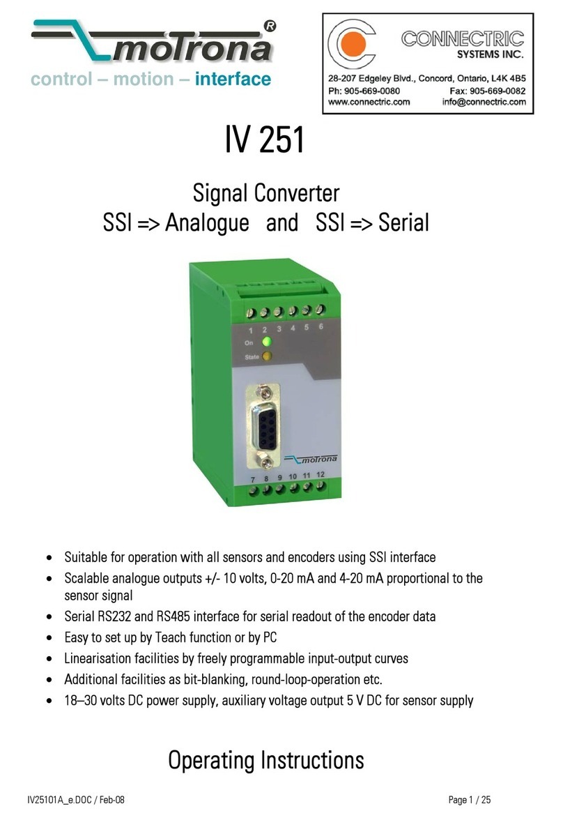
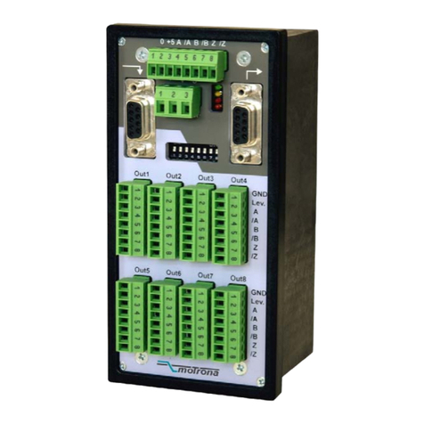
CONNECTRIC ENCODER-LAB02 User manual

Page 1
EncoderLAB
For Testing and Simulating Incremental Encoder signals
Part No. ENCODER-LAB02
Users Manual
®
!
"#"
$"%
&"
'(!"
")%*+
,""&""
!+"'(!
""
+
+-!%
Introduction

Page 2
Encoder Testing Mode - Operator button functions
.+
"&"/
+%+"&
+ "+
("-+%
ON
"!%
-01 1
21"
21&
01%!+.3&4"
!"01%'(!
"%
,+-
.3&4 (
($%
*!0
5+%+6
&7
6&"
"&%
3.8*&+9
+&!".3&4
+%!
":+ /&9
"
!5%9
++!
%
OFF
5!
&6+
Full size
Specifi cation
Mechanical
;82<
=><8?0
,8@
Input Power Supply
1
Power adapter
Australasia Only
*8921'
.81('%0
Testing Limits
A'><
B'
!0 2('
0
;#!0=C06=C
/
%
+5"
Encoder Termination
D(!"
?/"
'!+
Simulator Limits
;#!=C06=C
Input Power Supply
011('
/"
2
A Z BA Z0 + B
Tester Simulator
Incremental Encoder
Signal Tester and Simulator
ON
Select Voltage
OFF
Input Type
PP, NPN, PNP
1 Turn Signal
Input Source
Enter
Test PPR
Move Entry
1 Place Left
RUN
1 Pulse Hertz +
Hertz -
Change
Phase
Stop
Reset
PPR
Enter
Preset PPR
Move Entry
1 Place Left
Continuous
or 1 Cycle
www.pca-aus.com.au
PCA
TM
ire colour code label
Part No. ENC-TEST-SIM-11
To be ade clear
A 12345 >>> B 12345 Z 1 123 mA
A 12345 >>> B 12345 Z 1 123 kHz
olts InPut 1 TURN 1234 RPM
24/5 NPN Extnl
EncoderLAB
Area to place your own encoder wiring colour code

Page 3
!&&%("
!'(!"".;;%
&8"!.;;+!
!%
Input Type
"+<
"&47'((!
3D3 D3D DD%+"
&"9
+E3D3F+D3D EDDF "
&"++
!%
1 Turn Si nal Input Source
9
#9
6""+
%+&4<
"'(!"
+*%
External:<C9
"&
D0%
Internal:B%
Simulated:*"&
DD
:#%9
++<"&4%
Enter Test PPR
&49
DD%&!"
&4 &%
"'(!
&"'(!-%
Move Entry 1 Place Le#
&4
!9
%&6C
&4+!C%
Power Switch
*('"!%
Mode Switch
/"&""
+ /%
Plu 1
D(!.E;F3.8
D"?"
Plu 2
D(!+
"+%E;F
Plu 3
D(!+
%E;F
Plu 4
D(!9
%E>FG
3.8,/"&<
"6%
"6+&"&
-"+!%
Plu 5
D"6+0%0
6""+%
*<""
!%1('%0
"&%
Plu 6
H/+6%
Plu 7
I203"6+6%
OPERATOR PANEL
?/"9
+"&%
Rear Plug Wiring Panel
5
P6
P7
D0+

Page 4
Encoder Testing Procedure
Step 1
Turn on the power
D1"6
""&6%/
&6(
&"%
Step 2
Connect an encoder for test
&"
"! &3.&+%;"
"
%;"D(
!D+
%
J.1 0JB
JK1 @JL
J MJL
2J ?JLB
Step 3
Select the one turn input mode
+8
>%<D
0%&
B&"!
DD%
>%HB "
!DD &"
DD%
>%*&
" !!
+%,DD
& &!
%
Step 4
Select the ON button
"7-9
01 1 21
21&
01%
:<&
%
-&+!&"+
"!
%
"&!+&!
.;;&4 +
%*!+"
+5&%
++ ".3&4
!#
"+"9
%
(""
%
Step 5
Select the input type
+8
D3D8+<
"2%M6K!%
3D38+<
"2%M6.!
DD8<
"&"K.%.!
&":
2%M69
%
8*!
&".K!%
Step 6
Spin the encoder
+'(!
&"
&%B-4"!
" "!"#
"&DD%
3.%/!"
+ 9
&B!9
"%
(""&6"9
%
Step 7
Check for correct operation
%!
DD +%
%B!"
%+"&"
+"!LL
-4%
2%"!&&"
@ 0%
>!%
" <9
D><#!%3.
<D>DD&
&&!<
#!+%
26C &
;""!%*!&
#!&
D&6"
"%+"
!""
%

Page 5
Encoder Simulator Mode - Operator button functions
*+
<!#"
%&!9
!#"9
+
%
"+7+
!%."+!-
++&!-
"+#6!"9
+%+"
H3&4
+&"+&
"+H3&4
Full size
)
%
.+
"&"+
+ "
&/+%/(
"-+%
3.8"
+%
A Z BA Z0 + B
Tester Simulator
Incremental Encoder
Signal Tester and Simulator
ON
Select Voltage
OFF
Input Type
PP, NPN, PNP
1 Turn Signal
Input Source
Enter
Test PPR
Move Entry
1 Place Left
RUN
1 Pulse Hertz +
Hertz -
Change
Phase
Stop
Reset
PPR
Enter
Preset PPR
Move Entry
1 Place Left
Continuous
or 1 Cycle
www.pca-aus.com.au
PCA
TM
ire colour code label
Part No. ENC-TEST-SIM-11
To be ade clear
A
Count
12345
PreSet
12345
Mode 1 Cycle
123456 Hz
1234 RPM
12
>>>>>>>
Phase
B
A
EncoderLAB

Page 6
RUN/1 Cycle
&9
"+
&!+"'!&4
&"%*'++!
+/&4%,!
+&"&
DD )
DD!%
(""&6
7'(9
!" DD
"9
+"++%
STOP
(&+&4
(&6&6
%
Continuous or 1 Cycle
&"++&
DDH3&4<9
+&%
RESET PPR
DDC!
"&"%
Enter Preset PPR
&4
DD !"
&+&4
%
'((!""
&D/-%
Move Entry 1 Place Le#
&9
9
-
'((!8/"D/-
%
HERTZ +
*#!"
&4%
HERTZ -
(#!"
&4%
CHANGE PHASE:
&"LL
D+%
'((!8/"!
#"%,"+N
NN"#
6" "
6""!"!OOOO%
Step 1
Turn on the power
D1"6
""&6%/9
&6+
/(&"%
Step 2
Connect an adapter lead to P4
+"D$!
2
$!9
%
Step 3
Select the output mode of operation
"+8
Mode 1%Continuous
*#"+!
H3&4&%
Mode 2.1 Cycle
*&9
%&
"H3&4%
! H3&49
!%
Step 4
Select the PP simulation value
;DD&4D/
<-
>!D&4
!+!99
&%
;"0%
%DD
%.DDD&4" ""&
!
%.>&4!""
2%.&4-+0""&
!%
0%.>&4"9
!""0%
Step 5
un the output signals
.H3&4""&
4%(""&6
4%
Step 6
Change output frequency
.=CK=CP&49
#!%.+'D&4"
L+%
'(!"#"+
NNN"++
"6""6
%
Encoder Simulator Mode - Operator button functions
Encoder Simulation Procedure

Page 7
EncoderLAB So are Outline
!"!
%="&D'
H/"6"I20
6 %,
D'!9
+! 9
The total square waves for one shaft
revolution = PPR
These parameters are
all selectable on the
screen.
*;>."9
2"
#!%
Explanation of Computer Display Terms
&9
66++
+.%
!""+
"+
%*+-+9
!
&%

Page 8
Reporting Provisions
+%
;%-&!
+D'+
!#"%+
"!%
/+
+
#
%-
+" 9
+%
-%-"!+
!"6!
-+%3.8(!
#"-%
Net orking
!&&9
"6 &
D'+
"6%+-!-9
&&!+#%
-!!9
-%
Simulation Mode
%
PLEASE NOTE
"+! +
+"&"&
"""%&%%%

ENCODER LAB AUTOMATIC TEST MANUAL
+
++
+
.
..
.
+
++
+
!
"#$%$&
in
$'
()*+,-%!'
(
(./01'.(
1234/!!/54
(66(
3(#&(
&.(7 3#'
89:
7*;
7*<;!
= 3*;0(:>$
>4?@1$
A 8*!;*;
B C
@(*;*;'!
6
D 1E((
F .
E (
1:E
>#77$>&@$(
2(
(
G(
<HFI
'.'
((
(6
24(

ENCODER LAB AUTOMATIC TEST MANUAL
'
''
'
-
--
-
+
++
+
!
!!
!
/
//
/
:
::
:
Seng for test Selecon
opons
Explanaon of terms
A to test mode 3J%3 H#AI
6(
1.(6
E
Start meo t !BB ('
.6
E
Speed meo t !BB 6
Stop meo t !BB (
6
Voltage delay !B 9'6
Minim m speed !./#? 6
##/
C(
Speed Stability !BBK L6E
Speed T rns !BB 6

=
ENCODER LAB AUTOMATIC TEST MANUAL
/
//
/
:
::
:
Seng for test Selecon opons Explanaon of terms
Name 0 J
.<
Inp ts
M
M
%%
M%%%M
1
PPR ##/ C6
1 T rn Ref M
N
7@?
Test T rns OOOOO 6
Direcon &
/6
36
46
Test Volts BP
P
AP
A%BP
?6.
6
Inp t Type 1#1
#1#
##
3<
H/L Tolerance !BK L6C
6
H/L Max Span !BK LJ
C6
Phase Tolerance !
Phase Max Span ! ?LJ
Min C rrent !BB ?
Max C rrent !BB ?L
Print Report 5%1 #<
Add one to last
serial no.
5%1 3

A
ENCODER LAB AUTOMATIC TEST MANUAL
User Aborted 7 3#'
Start Timeo t 7 L
Stop Timeo t 7 L
Config Error H6I
Motor Timeo t ?6?7?7
L
Motor too Slow ??7G
A != PPR 16C##/
B != PPR 16C##/
Z != 1 1M6C
/A != PPR 1%6C##/
/B != PPR 1%6C##/
/Z != 1 1%M6C
A != B 16C6
A != /A 16C%6
B != /B 16C%6
DIR != AB (C
DIR != BA (C
DIR != /A/B (%%C%%
DIR != /B/A (%%C%%
A H/L too High 6+/BK-+%
A H/L too Low 6+/BK+%
A H/L Span Err J+/
L+%?L7
B H/L too High 6+/BK-+%
B H/L too Low 6+/BK+%
B H/L Span Err EE+/L+%?L7
Phase too High 6#-#
Phase too Low 6##
Phase Span Err #L#?L7
mA too Low ?2
mA too High ?L2
Low C rrent (2
High C rrent (+2
Z Inverted M6.6
6G?(6@
C<.G
Table of contents
Other CONNECTRIC Media Converter manuals