1
Conoptics Inc. 19 Eagle Rd. Danbury, CT 06810 Phone 800-748-3349 Fax 203-790-6145
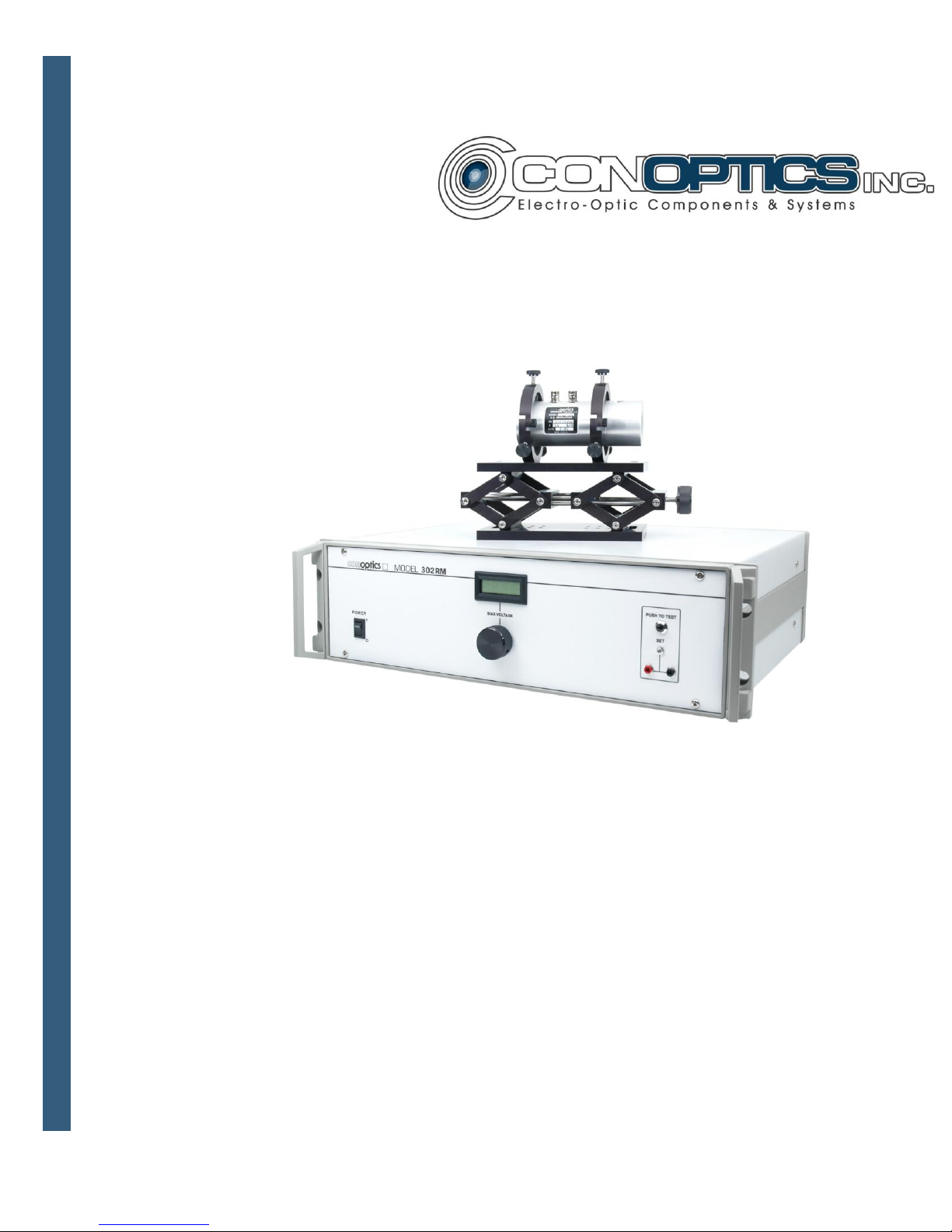
Overiview:
The Model 302RM is a Linear, high voltage, differential amplifier designed to drive a
capacitive load such as Conoptics 350, 360, 370 series E.O. modulators. The amplifier
is DC coupled and is capable of putting out a maximum of 750 volts peak-to-peak. The
input of the amplifier will accept either bipolar or unipolar signal formats and has a
switchable input impedance of either 50 ohms or 1K ohm. The maximum input level
requirement is 2V P-P for full output.
Caution Before Appying Power:
Please review this manual and become familiar with all safety markings and instructions.
Insure that the equipment mains (line) voltage as specified on the rear panel is in
accordance with desired AC source. Safe operation of this equipment may be
jeopardized by use other than specified by Conoptics.
Intended Use:
This equipment is designed for general laboratory use. It is intended to be used with a
number of Conoptics Electro-Optic Modulators only. The amplifier is designed to drive a
capacitive load that is floating with respect to ground. Any use other than in direct
connection with supplied optical modulator can result in severe damage to the amplifier
and potentially hazardous voltages to external equipment and personnel. This amplifier
must only be used in accordance with the detailed instructions provided in the manual.
Warning: Hazardous Voltage:
Hazardous AC and DC voltages are present on the center pins of the BNC connectors on
the rear panel marked J1 and J2 “AMPLIFIER OUTPUT”. No attempt should be made to
come into contact with these pins or to attempt to verify operation of the amplifier by
monitoring these connectors with an oscilloscope or other test equipment. In addition, the
equipment should be turned off before any of the supplied cables are connected to or
disconnected from the driver or modulator.