Table of Contents
Part 1 Disclaimer of Liability and
Limitation of Warranty 1
Part 2 Introduction to the CNC1/CNC2
box 2
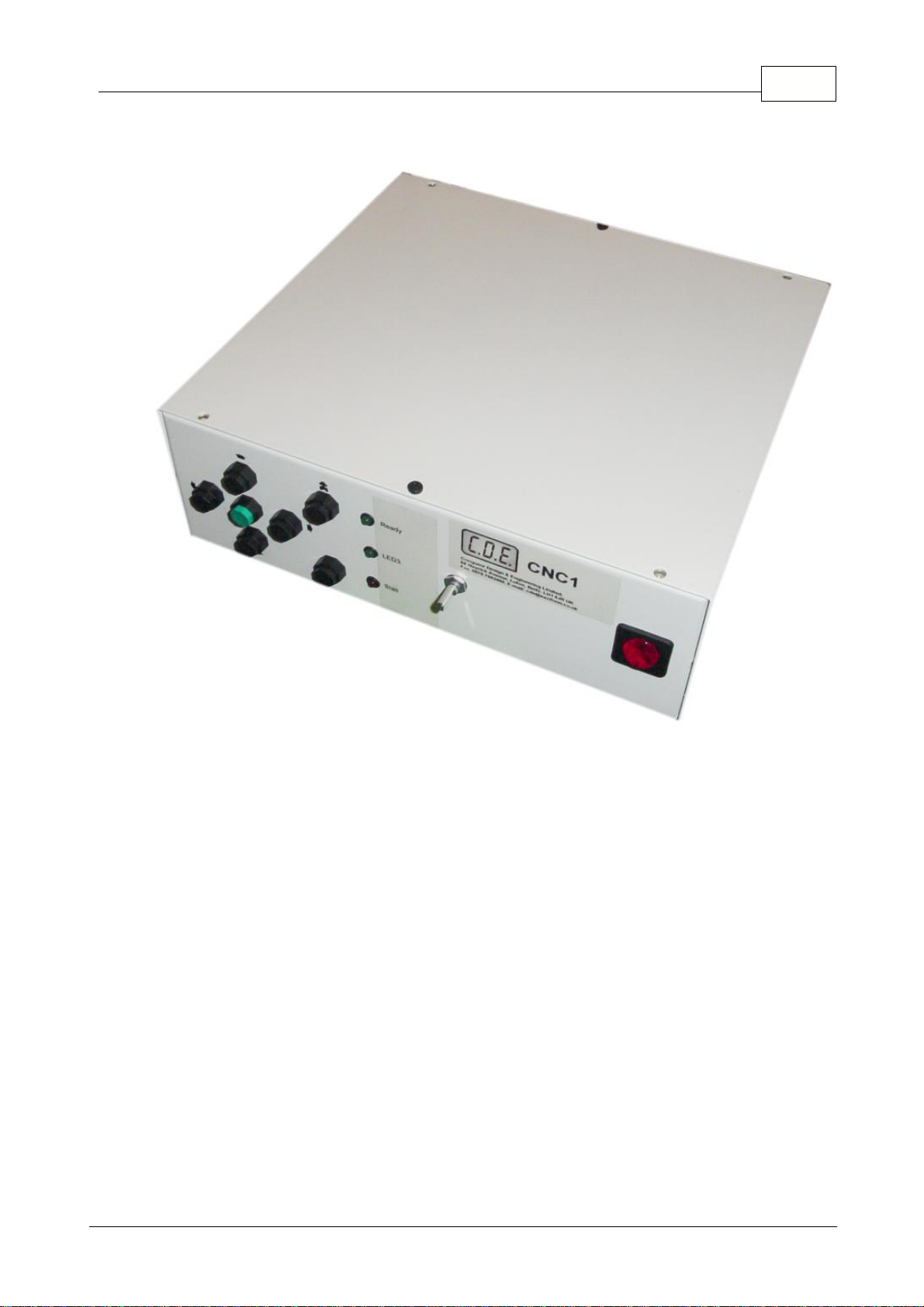
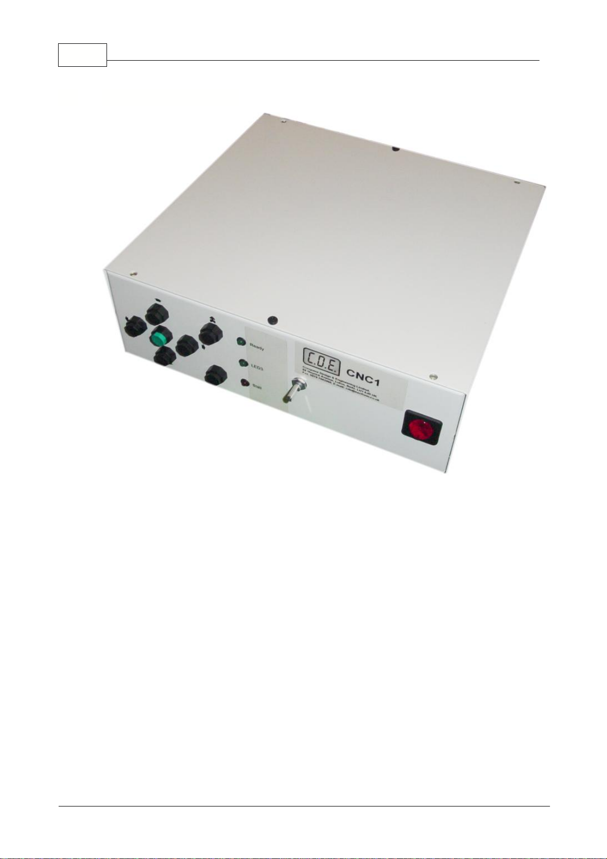
................................................................................................................................... 31 Front panel controls
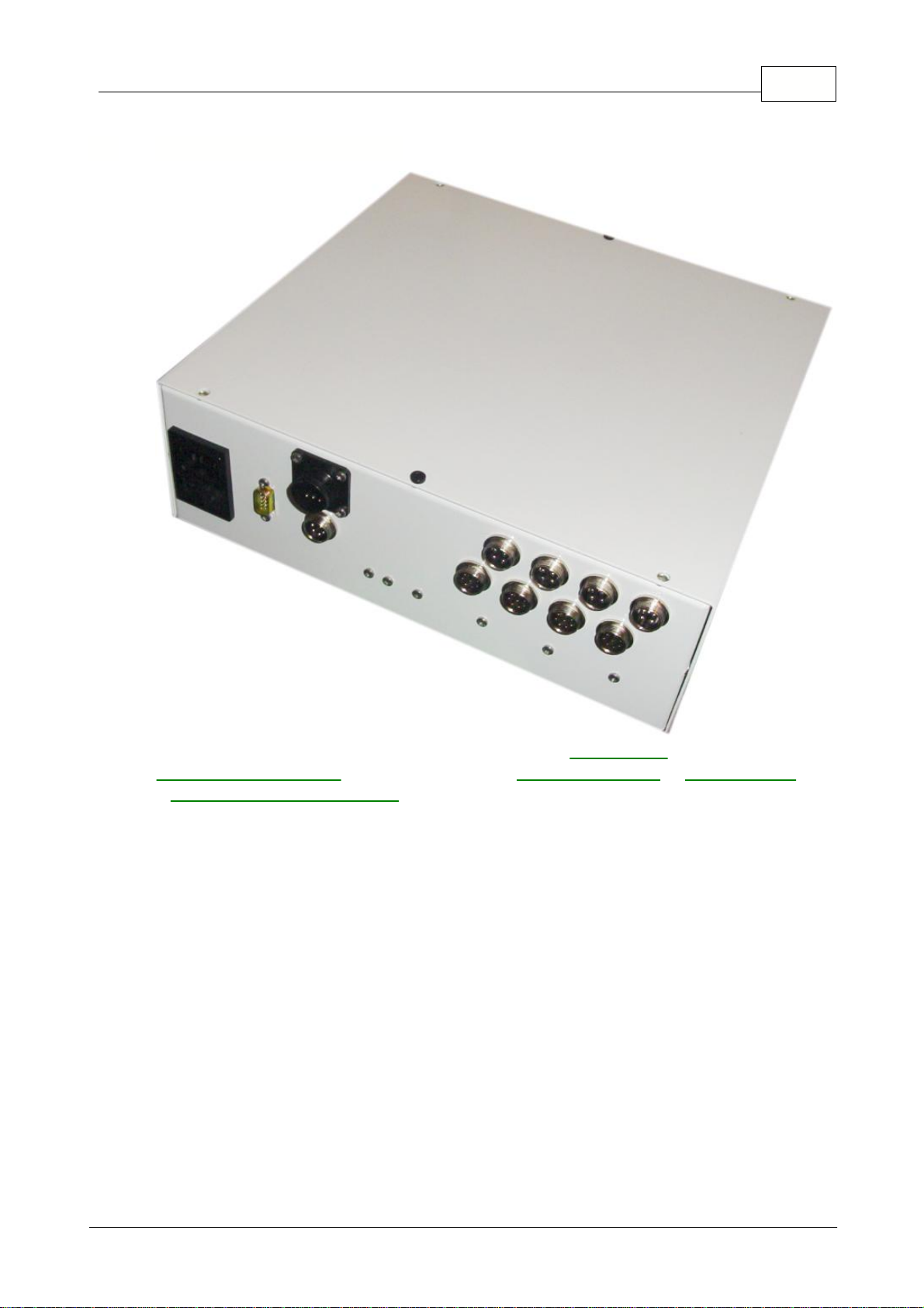
................................................................................................................................... 42 Rear Panel Connections
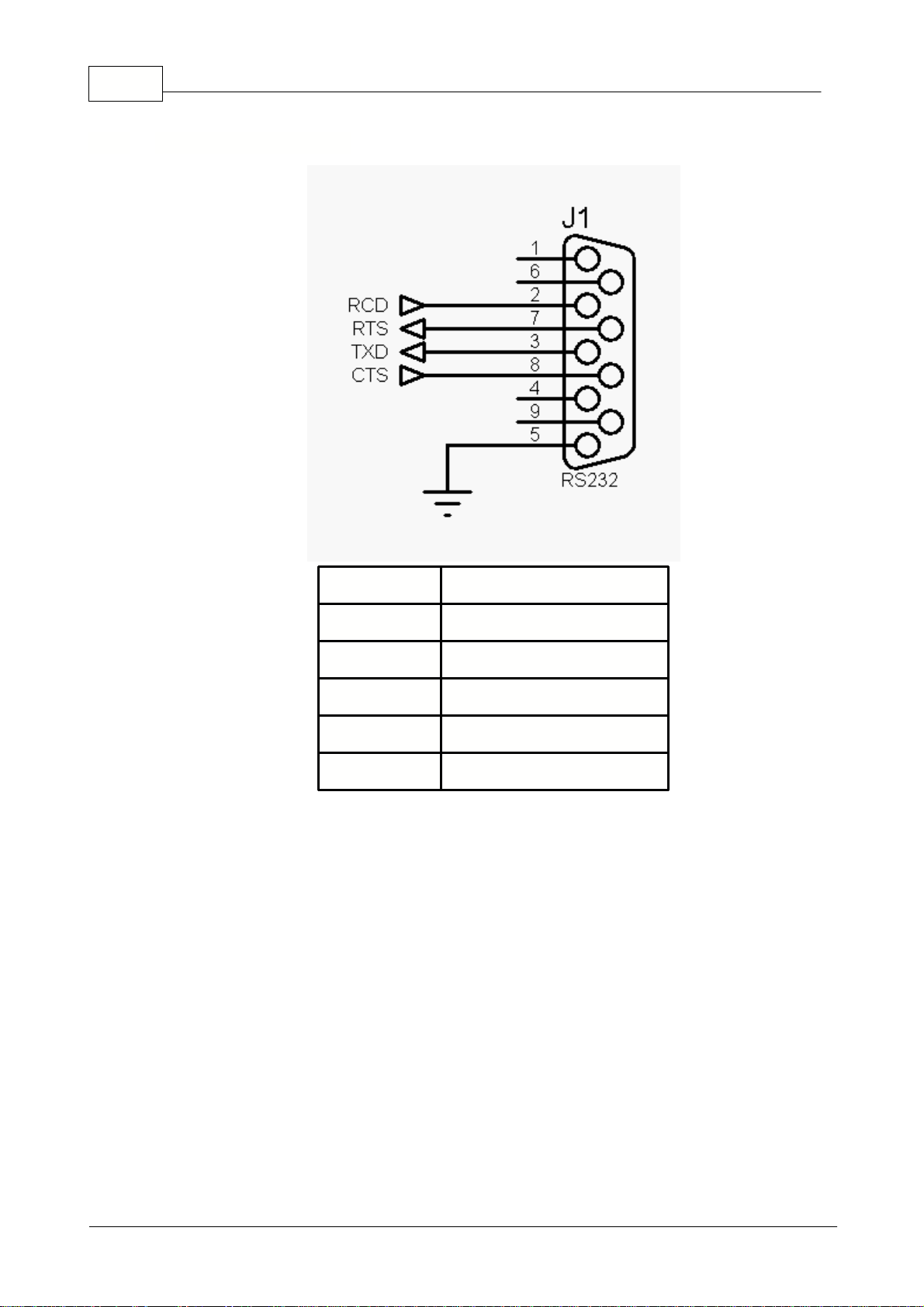
......................................................................................................................................................... 5RS232 Serial Interface
......................................................................................................................................................... 6Spindle Motor control plug
......................................................................................................................................................... 7Relay drives plug
......................................................................................................................................................... 8Stepper motor plug
......................................................................................................................................................... 9Feed-back/Encoder/Limit-switchplug
................................................................................................................................... 103 Spare and replacement plugs
Part 3 Manual Operation without a
Computer 11
Part 4 Appendices 12
................................................................................................................................... 121 Compatible Motors
................................................................................................................................... 132 G-Codes
......................................................................................................................................................... 14Additional G-Codes for Lathe Operations
......................................................................................................................................................... 15Additional G-Codes for Milling Operations
................................................................................................................................... 163 M-Codes
................................................................................................................................... 174 Command Set
................................................................................................................................... 195 Control Parameters
Index 24
IContents
I
Copyright©2005ConquerorDesignandEngineeringLtd.