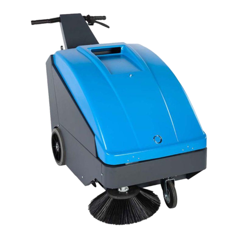
CONQUEST PB120E User manual

CONQUEST PB120E
FLOOR SWEEPER
OPERATOR MANUAL
T: 1800 826 789
E: support@conquestequipment.com.au
W: conquestequipment.com.au
IS120E-OM-V03

2

-1
Please read and comply with
these original instructions prior
to the initial operation of your appliance and
store them for later use or subsequent own-
ers.
Your sales outlet should be informed about
any transit damage noted when unpacking
the product.
–Warning and information plates on the
machine provide important directions
for safe operation.
–In addition to the information contained
in the operating instructions, all statuto-
ry safety and accident prevention regu-
lations must be observed.
Notes on the content materials (REACH)
Current information on content materials
can be found at:
www.isalsweepers.com
The warranty terms published by the rele-
vant sales company are applicable in each
country. We will repair potential failures of
your appliance within the warranty period
free of charge, provided that such failure is
caused by faulty material or defects in man-
ufacturing. In the event of a warranty claim
please contact your dealer or the nearest
authorized Customer Service centre.
Please submit the proof of purchase.
DANGER
To avoid risks, all repairs and replacement
of spare parts may only be carried out by
authorized customer service personnel.
–Only use accessories and spare parts
which have been approved by the man-
ufacturer. The exclusive use of original
accessories and original spare parts
ensures that the appliance can be oper-
ated safely and trouble free.
DANGER
Warns about immediate danger which can
lead to severe injuries or death.
몇WARNING
Warns about possible danger which could
lead to severe injuries or death.
몇CAUTION
Points out a possibly dangerous situation
which can lead to light injuries or property
damage.
ATTENTION
Pointer to a possibly dangerous situation,
which can lead to property damage.
General notes . . . . . . . . . . . . . EN 1
Environmental protection EN 1
Warranty . . . . . . . . . . . . EN 1
Accessories and Spare
Parts. . . . . . . . . . . . . . . . EN 1
Symbols in the operating in-
structions . . . . . . . . . . . . EN 1
Symbols on the machine EN 1
Proper use. . . . . . . . . . . . . . . . EN 2
Foreseeable misuse. . . . EN 2
Suitable surfaces . . . . . . EN 2
Safety instructions . . . . . . . . . . EN 2
Safety instructions concern-
ing the operation . . . . . . EN 2
Safety information concern-
ing the driving operation. EN 2
Safety instructions for bat-
tery-operated devices . . EN 2
Appliances with high empty-
ing system . . . . . . . . . . . EN 3
Devices with overhead
guard . . . . . . . . . . . . . . . EN 3
Safety information concern-
ing the transport of the appli-
ance . . . . . . . . . . . . . . . . EN 3
Safety information concern-
ing maintenance and care EN 3
Function. . . . . . . . . . . . . . . . . . EN 3
Unloading tips . . . . . . . . . . . . . EN 3
Operating and Functional Ele-
ments. . . . . . . . . . . . . . . . . . . . EN 4
Illustration of sweeper . . EN 4
Operating field . . . . . . . . EN 4
Before Startup . . . . . . . . . . . . . EN 5
Lock/ release parking brake EN 5
Start up . . . . . . . . . . . . . . . . . . EN 5
General notes . . . . . . . . EN 5
Inspection and maintenance
work . . . . . . . . . . . . . . . . EN 5
Safety notes regarding the
batteries . . . . . . . . . . . . . EN 5
Charge the batteries . . . EN 5
Operation. . . . . . . . . . . . . . . . . EN 5
Adjusting driver's seat . . EN 5
Starting the machine . . . EN 6
Drive the machine . . . . . EN 6
Sweeping mode . . . . . . . EN 6
Emptying waste container EN 6
Turn off the appliance . . EN 7
Transport . . . . . . . . . . . . . . . . . EN 7
Storage/decommissioning . . . . EN 7
Care and maintenance . . . . . . EN 7
General notes . . . . . . . . EN 7
Cleaning. . . . . . . . . . . . . EN 7
Maintenance intervals . . EN 7
Maintenance Works . . . . EN 7
Troubleshooting. . . . . . . . . . . . EN 1
1
Technical specifications. . . . . . EN 1
1
EU Declaration of Conformity . EN 1
2
General notes
Environmental protection
The packaging material can be
recycled. Please do not throw the
packaging material into house-
hold waste; please send it for re-
cycling.
Old appliances contain valuable
materials that can be recycled.
Please arrange for the proper re-
cycling of old appliances. Please
dispose your old appliances us-
ing appropriate collection sys-
tems.
Batteries, oil, fuels and similar substances
must not be released into the environ-
ment. Please dispose of these substances
via suitable collection systems.
Warranty
Accessories and Spare Parts
Symbols in the operating
instructions
Symbols on the machine
Risk of burns on account
of hot surfaces! Allow the
exhaust to cool down suf-
ficiently before starting
work on the machine.
Always use appropriate
gloves while working on
the device.
Risk of getting squeezed
on account of getting
jammed between vehicle
parts.
Risk of injury on account
of moving parts. Do not
reach in.
Risk of fire. Do not vacu-
um up any burning or
glowing objects.
Chain pick-up / crane
point
Intake points for the jack
Maximum decline of
ground when driving with
the waste container
raised.
The gradient in the direc-
tion of travel should not
exceed 14 %.
Caution! Rotating brush
(watch for rotation direc-
tion).
15EN

-2
The sweeper is intended for cleaning floor
surfaces for commercial use and e.g. for
the following fields of application:
Car parks
Production facilities
Logistics areas
Hotel
Retail industry
Storage areas
Walkways
–This sweeper has been designed to
sweep dirt and debris from indoor as
well as outdoor surfaces.
–The machine with working equipment
must be checked to ensure that it is in
proper working order and is operating
safely prior to use. Otherwise, the appli-
ance must not be used.
–Use this sweeper only as directed in
these operating instructions.
–The machine may not be modified.
–The machine is only suitable for use on
the types of surfaces specified in the
operating instructions.
–The machine may only be operated on
the surfaces approved by the company
or its authorised representatives.
–The following applies in general: Keep
highly-flammable substances away
from the appliance (danger of explo-
sion/fire).
Never vacuum up explosive liquids,
combustible gases or undiluted acids
and solvents. This includes petrol, paint
thinner or heating oil which can gener-
ate explosive fumes or mixtures upon
contact with the suction air. Acetone,
undiluted acids and solvents must also
be avoided as they can harm the mate-
rials on the machine.
Never sweep/vacuum up reactive metal
dusts (e.g. aluminium, magnesium,
zinc), as they form explosive gases
when they come in contact with highly
alkaline or acidic detergents.
Do not sweep/vacuum up any burning
or glowing objects.
The appliance is not suitable for sweep-
ing off hazardous substances.
The machine may not be used or stored
in hazardous areas. It is not allowed to
use the appliance in hazardous loca-
tions.
It is strictly prohibited to take co-pas-
sengers.
Pushing/pulling or transporting objects
by means of this appliance is prohibit-
ed.
–Asphalt
–Industrial floor
–Screed
–Concrete
–Paving stones
In order to maintain clearance and
creepagedistances,thedevicemaynot
be operated over 2000 metres above
sea level.
(ApplicableforFinlandonly)The device
may not be used at low ambient tem-
peratures (below 0°C) if it is equipped
with a PVC hose line. Contact ISAL if
you should have questions regarding
your device.
The machine with working equipment
must be checked to ensure that it is in
proper working order and is operating
safely prior to use. Otherwise, the appli-
ance must not be used.
If the appliance is used in hazardous ar-
eas (e.g. filling stations) the corre-
sponding safety provisions must be ob-
served. It is not allowed to use the ap-
pliance in hazardous locations.
DANGER
Risk of injury!
Do not use the appliance without an
overhead guard in areas where the op-
erator might get hit by falling objects.
The operator must use the appliance
properly. The person must consider the
local conditions and must pay attention
to third parties, in particular children,
when working with the appliance.
It is important to follow all safety instruc-
tions, rules and regulations applicable
for driving motor vehicles.
Priortostarting work,theoperatormust
ensure that all protective devices are
properly installed and function correct-
ly.
The operator of the appliance is liable
for accidents with other individuals or
their property.
Ensure that the operator wears tight-fit-
ting clothes. Wear sturdy shoes and
avoid wearing loose-fitting clothes.
Check the immediate vicinity prior to
starting (e.g. children). Ensure suffi-
cient visibility!
Never leave the machine unattended
so long as the engine is running. The
operator may leave the appliance only
when the engine has come to a stand-
still, the appliance has been protected
against accidental movement, and the
key has been removed.
Please remove the key, when not in
use, to avoid unauthorised use of the
appliance.
The appliance may only be used by per-
sons who have been instructed in han-
dling the appliance or have proven
qualification and expertise in operating
the appliance or have been explicitly
assigned the task of handling the appli-
ance.
This appliance is not intended for use
by persons (including children) with lim-
ited physical, sensoric or mental capac-
ities or lack of experience and/or skills,
unless such persons are accompanied
andsupervisedbyapersoninchargeof
their safety or if they received precise
instructions on the use of this appli-
ance.
Children should be supervised to pre-
vent them from playing with the appli-
ance.
CAUTION
Risk of damage! Do not sweep up straps,
strings or wires as these may wrap around
the brush roller.
DANGER
Risk of injury! Verify the stability of the
ground prior to driving on it.
DANGER
Risk of accident, risk of injury!
Danger of tipping if gradient is too high.
–The gradient in the direction of travel
should not exceed 14 %.
Danger of tipping over when taking bends
at high speed (particularly left-hand bends).
–Drive slowly when cornering.
Danger of tipping on unstable ground.
–Only use the machine on sound surfac-
es.
Danger of tipping with excessive sideways
tilt.
–The gradient perpendicular to the direc-
tion of travel should not exceed 10%.
Note: Claims may only be made under
guarantee if you use the batteries and
chargers recommended by ISAL.
–Always follow the instructions of the
battery manufacturer and the charger
manufacturer. Please follow the statu-
tory requirements for handling and dis-
posing batteries.
Beware of dangerous
electrical current!
Pay attention to the in-
struction.
Steer slowly!
Please read the operating
instructions and act ac-
cordingly!
Risk of damage!
Do not rinse out the dust
filter.
Proper use
Foreseeable misuse
Suitable surfaces
Safety instructions
Safety instructions concerning the
operation
Safety information concerning the
driving operation
Safety instructions for battery-
operated devices
16 EN

-3
–Never leave the batteries in a dis-
charged state; recharge them as soon
as possible.
–Always keep the batteries clean and dry
to avoid creep currents. Protect the bat-
teries and avoid contact with impurities
such as metal dust.
–Do not place tools or similar items on
the battery. Risk of short-circuit and ex-
plosion.
–Do not work with open flames, generate
sparks or smoke in the vicinity of a bat-
tery or a battery charging room. Danger
of explosion.
–Do not touch hot parts of the machine
such as the drive motor (risk of burns).
–Be careful while handling battery acid.
Follow the respective safety instruc-
tions!
–Used batteries are to be disposed ac-
cording to the EC guideline 91/ 157
EWG in an environment-friendly man-
ner.
DANGER
Risk of injury!
When working on the high emptying
system, completely lift and secure the
waste container.
Perform the safeguarding only from
outside the hazard zone.
NOTICE
The overhead guard (optional) protects the
driver against larger falling objects. Howev-
er, it does not provide rollover protection!
Check the overhead guard for damage
daily.
If the overhead guard, as well as indi-
vidual elements, should be damaged,
replace the entire overhead guard.
Any modification of the overhead guard
and installation of elements, compo-
nents and assemblies other than those
approved by ISAL is not permitted and
may limit the function of the overhead
guard.
Observe the net weight (transport
weight) of the device during transport
on trailers or vehicles.
To transport the device, unplug the bat-
tery plug and securely fasten the de-
vice.
First switch off the appliance and re-
move the key before performing any
cleaning or maintenance tasks on the
appliance, replacing parts or switching
over to another function.
When performing any service and
maintenance work on devices with a
traction battery, the battery must be dis-
connected from the electrical system of
the device via the battery isolation point
(battery plug).
Always disconnect the battery when
working on the electrics.
To do this, first disconnect the negative
terminal and then the positive terminal.
Reconnection is performed in reverse
sequence. Connect the positive termi-
nal first, then connect the negative ter-
minal.
Do not clean the appliance with a water
hose orhigh-pressure water jet(danger
of short circuits or other damage).
Maintenance work may only be carried
out by approved customer service out-
lets or experts in this field who are famil-
iar with the respective safety regula-
tions.
Please observe the local safety regula-
tions regarding portable commercially
used appliances.
Always use appropriate gloves while
working on the device.
The sweeper operates using the sweep-
shovel principle.
–The rotating roller brush moves the dirt
directly into the waste container.
–The side brush cleans the corners and
edges of the surface and moves dirt
and debris into the path of the roller
brush.
–The fine dust is sucked in via the dust
filter through the suction blower.
Danger
Risk of injury, risk of damage!
Observe the weight of the appliance when
you load it!
Do not use a forklift.
Use a suitable ramp or a crane to load
the appliance!
Observe when using a ramp:
Ground clearance 70 mm.
If the machine is delivered on a pallet,
you must create an unloading ramp us-
ing the boards provided.
You will find the instructions for this pro-
cedure on page 2 (inside of cover).
Important instruction: every board
must be attached with at least 2 screws.
Appliances with high emptying
system
Devices with overhead guard
Safety information concerning the
transport of the appliance
Safety information concerning
maintenance and care
Function
Unloading tips
Weight (without batteries) 750 kg*
Weight (with batteries) 1200 kg*
* If upgrade kits are installed, the weight is
respectively higher.
17EN

-4
Illustration
1 Nameplate
2 Seat (with seat contact switch)
3 Steering wheel
4 Lock of appliance hood
5 Cover
6 Side brush, right
7 Front wheel
8 Roller brush access
9 Lashing point
10 Beacon lamp
11 Appliance cover right side
12 Cover, right
13 Tail panel
14 Drive wheel
15 Cover, left
16 Bonnet left side (engine bonnet)
17 Battery set
not included in the delivery
Illustration
1 Roller brush and side brush control le-
ver
Lever forwards: Switches the roller
brush on and lowers and switches the
side brushes on.
Lever backwards: Switches the roller
brush on
2 Control lever waste container
Raise/lower waste container
3 Roller brush control lever
Raises and lowers the roller brush
4 Control lever container flap
Open/close container lid
5 Indicator lamps and display
6 Switch blower and filter cleaning
Position centred: Filter cleaning and
blower off
Rear position: Blower on
Front position: Filter cleaning on
7 Horn switch
8 Fuses
9 Ignition lock
Position 0: Switch off engine
Position 1: Ignition on
Position 2: Start the engine
10 Selector for the direction of travel
11 Parking brake
12 Roller brush wear adjustment / sweep-
ing area setting
13 Battery socket
Illustration
1 Brake pedal
2 Drive pedal
Illustration
1 Battery capacity
2 Battery control lamp
3 Control lamp operating state
4 Indicator lamp for position lights
5 Indicator lamp (not connected)
6 Indicator lamp for dipper
7 Indicator lamp (not connected)
8 Indicator lamp - forward driving direc-
tion
9 Indicator lamp - reverse driving direc-
tion
10 Operating hour counter
Operating and Functional Elements
Illustration of sweeper Operating field
Pedals
Indicator lamps and display
18 EN

-5
Loosen parking brake; press brake
pedal at the same time.
Activate the parking brake; press brake
pedal at the same time.
Park the sweeper on an even surface.
Remove ignition key.
Lock parking brake.
Check battery charging status; charge
batteries it if required (see Chapter
"Charging the batteries").
Check the sweeping roller and the side
brush for wear and wrapped belts.
Check the wheels for tied up belts.
Check function of all operator control el-
ements.
Check appliance for damages.
Clean the dust filter with the filter clean-
ing button.
Note: For description, see section on Care
and maintenance.
Please observe the following warning notes
when handling batteries:
Danger
Riskofexplosion! Donotputtoolsorsimilar
on the battery, i.e. on the terminal poles
and cell connectors.
Danger
Risk of injury! Ensure that wounds never
come into contact with lead. Always clean
your hands after having worked with batter-
ies.
Danger
Risk of fire and explosion!
–Smoking and naked flames are strictly
prohibited.
–Rooms where batteries are charged
must have good ventilation because
highly explosive gas is emitted during
charging.
Danger
Danger of causticization!
–Rinsethoroughly withlotsofclearwater
if acid gets into the eye or comes in con-
tact with the skin.
–Then consult a doctor immediately.
–Wash off the acid If it comes in contact
with the clothes.
CAUTION
Chargethebatteriesbeforecommissioning
the machine.
DANGER
Risk of injury! Comply with safety regula-
tions on the handling of batteries. Observe
thedirectionsprovidedbythemanufacturer
of the charger.
Please read and follow the included operat-
inginstructionsbythebatterymanufacturer
and follow them.
Chargethebattery onlywith anappropriate
charger.
Danger
Danger of chemical burns. Adding water to
the battery in its discharged state can
cause the acid to leak! Use safety glasses
while handling battery acid and follow the
safety instructions to avoid personal injury
or damage to clothes. Should the acid
spray on to the skin or clothes, rinse imme-
diately with lots of water.
CAUTION
Risk of damage. Use only distilled or desal-
inated water (VDE 0510) for filling the bat-
tery. Do not add any substances (so-called
performance improving agents), else war-
ranty claims will not be entertained.
The use of other batteries and chargers is
not recommended and may only take place
after consulting with ISAL customer ser-
vice.
Pull the battery plug from the machine
and connect it to the plug of the charg-
er.
Connect the plug of the charger to a
proper socket of 16 A, the charger will
charge automatically.
Always keep both motor covers open
during the charging process.
Note: When the batteries are charged,
first remove the charger from the mains
and then disconnect it from the batter-
ies.
CAUTION
Be sure to observe the battery manufactur-
er’s instructions and then act accordingly.
–Display of the battery capacity in the
green range:
Battery is charged.
–Display of the battery capacity in the
yellow range:
Battery is halfway discharged.
–Display of the battery capacity in the red
range:
Battery is almost discharged. The
sweeping mode will be shortly switched
off automatically.
–Indicator lamp glows red
Battery is discharged. The sweeping
mode will be terminated automatically
(the sweeping aggregates cannot be
taken into operation until the battery is
charged).
Drive the machine directly to the charg-
ing station; avoid any steep gradients in
the process.
Charge battery.
1 Lever for seat adjustment
2 Driver seat
Pull seat adjustment lever outwards.
Before Startup
Lock/ release parking brake
Start up
General notes
Inspection and maintenance work
Daily before starting operations
Safety notes regarding the batteries
Observe the directions on the
battery, in the instructions for
use and in the vehicle operat-
ing instructions!
Wear an eye shield!
Keep away children from acid
and batteries!
Risk of explosion!
Fire, sparks, open light, and
smoking not allowed!
Danger of causticization!
First aid!
Warning note!
Disposal!
Do not throw the battery in the
dustbin!
Beware of dangerous electrical
current!
Charge the batteries
Recommended batteries, chargers
Order number
Battery pack 36 V,
360 Ah, (in the trough,
low maintenance) *
6.654-282.0
Charger 36 V, 50 A 6.654-283.0
* Appliance requires 1 battery pack
Check fluid level in the battery and
adjust if required
Check charging status of battery
Operation
Adjusting driver's seat
19EN

-6
Slide seat, release lever and lock in
place.
Check that the seat is properly locked in
position by attempting to move it back-
wards and forwards.
Note: The machine is equipped with a seat
contact switch If the driver's seat is vacat-
ed, the machine is switched off.
Sit on the driver's seat.
Bring the direction selector switch into
the middle position.
Lock parking brake.
Insert the ignition key into the ignition
switch.
Turn the ignition key to position "I".
The appliance is now ready for opera-
tion.
Turn the ignition key to position "II".
The appliance can now be driven.
Note: The display of the battery capac-
ity will show the actual charge status af-
ter about 10 seconds.
Press brake pedal and keep it de-
pressed.
Release parking brake.
1 Forward travel direction
2 Direction of travel reverse
Set the travel direction switch to "for-
ward".
Press accelerator pedal down slowly.
Danger
Risk of injury! While reversing, ensure that
there is nobody in the way, ask them to
move if somebody is around.
CAUTION
Risk of damage! Only use the direction
switch when the machine is standing still.
Set the travel direction switch to "back-
wards".
Press accelerator pedal down slowly.
–The accelerator pedal can be used to
vary the driving speed infinitely.
–Avoid pressing the pedal suddenly as
this may damage the hydraulic system.
Release the accelerator pedal, the ma-
chine brakes automatically and stops.
Note: The braking effect can be supported
by pressing the brake pedal.
Driving over fixed obstacles which are 70
mm high or less:
Drive forwards slowly and carefully.
Driving over fixed obstacles which are
more than 70 mm high:
Only drive over these obstacles using a
suitable ramp.
ATTENTION
Do not sweep up packing strips, wire or
similar objects as this may damage the
sweeping mechanism.
Note: To achieve an optimum cleaning re-
sult, the driving speed should be adjusted
to take specific situations into account.
Note: During operation, the dust filter
should be shaken off and cleaned at regu-
lar intervals.
Note: When frequently working in areas
with fine dust, the filter must be cleaned
more often.
1 Roller brush and side brush control le-
ver
2 Control lever waste container
3 Roller brush control lever
4 Control lever container flap
Roller brush and side brush control le-
ver
Control lever (1) forwards: Switches the
roller brush on and lowers and switches
the side brushes on.
Control lever (1) backwards: Switches
the roller brush on.
Control lever waste container
Control lever waste container (2) to the
front: Waste container is lowered.
Control lever waste container (2) to the
back: Waste container is raised.
Control lever roller brush
Roller brush control lever (3) forwards:
Raises the roller brush.
Roller brush control lever (3) back-
wards: Lowers the roller brush.
Control lever container flap
Control lever container flap (4) to the
front: The container flap of the waste
container opens.
Control lever container flap (4) to the
back: The container flap of the waste
container closes.
Switch on the blower.
With surface cleaning:
Roller brush and side brush control le-
ver (1) backwards: Switches the roller
brush on.
Roller brush control lever (3) back-
wards: Lowers the roller brush.
Control lever container flap (4) to the
front: Container flap opens.
With cleaning of side edges:
Roller brush and side brush control le-
ver (1) forwards: Switches the roller
brush on, switches the side brushes on
and lowers them.
Roller brush control lever (3) back-
wards: Lowers the roller brush.
Switch off the blower.
With surface cleaning:
Roller brush and side brush control le-
ver (1) backwards: Switches the roller
brush on.
Roller brush control lever (3) back-
wards: Lowers the roller brush.
Control lever container flap (4) to the
front: Container flap opens.
With cleaning of side edges:
Roller brush and side brush control le-
ver (1) forwards: Switches the roller
brush on, switches the side brushes on
and lowers them.
Roller brush control lever (3) back-
wards: Lowers the roller brush.
DANGER
Risk of injury!
During the emptying process, persons
and animals must not stay within the
swivelling range of the waste container.
Danger of tipping!
Place the device on an even surface
during the emptying process.
몇WARNING
Risk of crushing!
Never reach into the rod assembly for
the drainage mechanism. Do not stay
under the raised container.
ATTENTION
Risk of personal injury or damage!
Material of the rotating roller brush may
be catapulted off during the emptying
process. Keep an appropriate distance.
Starting the machine
Drive the machine
Drive forward
Reverse drive
Driving method
Brakes
Driving over obstacles
Sweeping mode
Control lever
Sweeping dry floors
Sweeping damp or wet floors
Emptying waste container
20 EN

-7
Raise the roller brush and side brushes
using the control levers: Control lever 1
to middle position and control lever 3
forwards.
Close the container flap, in order to do
so, move the control lever (4) to the
back:
Raise the container flap, in order to do
so, move the waste container control le-
ver (2) to the back:
Slowly drive towards the collection con-
tainer.
Lock parking brake.
Open the container flap, in order to do
so, push the container flap operating le-
ver (4) to the front and empty the waste
container.
Close the container flap, in order to do
so, push the container flap operating le-
ver (4) to the back until it is tipped in-
wards in the end position.
Release parking brake.
Drive away the collection container
slowly.
Lower the waste container into the end
position, in order to do so, move the
waste container control lever (2) to the
front
Press brake pedal and keep it de-
pressed.
Lock parking brake.
Turn ignition key to "0" and remove it.
DANGER
Transport damage!
Observe the net weight (transport
weight) of the device during transport
on trailers or vehicles.
When transporting in vehicles, secure
the appliance according to the guide-
lines from slipping and tipping over.
Turn ignition key to "0" and remove it.
Lock parking brake.
Secure the appliance at the lashing
points (4x) using tension belts, ropes or
chains.
Secure the wheels of the machine with
wheel chocks.
Disconnect the battery of the sweeper
during transport.
DANGER
Risk of injury and damage! Note the weight
of the appliance in case of storage.
Park the sweeper on a level surface in
a dry, frost protected area. Protect it
against dust by means of covering ma-
terial.
Raise the roller brush and the side-
brushes to prevent the bristles from be-
ing damaged.
Close the container flap.
Turn ignition key to "0" and remove it.
Lock parking brake.
Lock the sweeper to ensure that it does
not roll off.
Additionally observe the following points if
the sweeper is not used over a longer peri-
od of time:
Clean the inside and outside of the
sweeper.
Remove the battery plug from machine.
Charge battery and recharge it approx.
every 2 months.
ATTENTION
Risk of damage!
Do not rinse out the dust filter.
Maintenance work may only be carried
out by approved customer service out-
lets or experts in this field who are famil-
iar with the respective safety regula-
tions.
Mobile appliances used for commercial
purposes are subject to safety inspec-
tions according to VDE 0701.
Park the sweeper on an even surface.
Turn ignition key to "0" and remove it.
Lock parking brake.
CAUTION
Risk of damage!
Do not clean the appliance with a water
hose orhigh-pressure water jet(danger
of short circuits or other damage).
DANGER
Risk of injury!
Wear dust mask and protective gog-
gles.
Clean machine with a cloth.
Blow through machine with com-
pressed air.
Clean the machine with a damp cloth
which has been soaked in mild deter-
gent.
Note: Do not use aggressive cleaning
agents.
Note: The elapsed-time counter shows the
timing of the maintenance intervals.
Note: If maintenance is carried out by the
customer, all service and maintenance
work must be carried out by qualified staff.
An ISAL specialist dealer can be consulted
at any time if needed.
Daily maintenance:
Check the sweeping roller and the side
brush for wear and wrapped belts.
Check function of all operator control el-
ements.
Check appliance for damages.
Weekly maintenance:
Check hydraulic unit.
Check the hydraulic oil level.
Check brake fluid status.
Check the pad for wear, replace if re-
quired.
Check the container lid and lubricate it.
Maintenance following wear:
Replace sealing strips.
Readjust the side seals or replace
them.
Replace roller brush.
Replace side brush.
Note: For description, see section on Main-
tenance work.
Maintenance to be carried out after 50
operating hours:
Have the first inspection done accord-
ing to the service manual.
Maintenance to be carried out after 250
operating hours:
Have the inspection done according to
the service manual.
Note: In order to preserve warranty claims,
all servicing and maintenance work during
the warranty period has to be performed by
an authorised ISAL Customer Service, in
accordance with the inspection check list.
Preparation:
Park the sweeper on an even surface.
Turn ignition key to "0" and remove it.
Lock parking brake.
DANGER
Risk of injury! Always apply the safety bar
when the waste container is raised.
1 Holder of safety rod
Turn off the appliance
Transport
Storage/decommissioning
Care and maintenance
General notes
Cleaning
Cleaning the inside of the machine
External cleaning of the appliance
Maintenance intervals
Maintenance by the customer
Maintenance by Customer Service
Maintenance Works
General notes on safety
21EN

-8
2 Safety rod
Fold the safety rod for the high empty-
ing up and insert it into the holder (se-
cured).
The batteries can only be exchanged as a
set. The exchange has to be performed by
trained personnel.
Due to the heavy weight (450 kg), the
batteries must be exchanged using a
crane.
Note: The cross strut must be un-
screwed prior to replacing the battery.
When removing the battery, disconnect
the negative terminal wire first.
Fasten the crane chains in the four eye-
lets of the battery set and carefully lift
out the batteries.
DANGER
Risk of injury!
Always apply the safety rod when the
waste container is raised.
Perform the safeguarding only from
outside the hazard zone.
1 Holder of safety rod
2 Brake fluid container
3 Closing head
Move up the waste container and se-
cure it by means of the safety rod, see
Chapter "Emptying the waste contain-
er"
Check if the there is enough brake fluid
in the brake fluid reservoir.
Note
The filling level has to be between Min.
and Max.
If necessary, refill DOT brake fluid cur-
rently commercially available.
NOTICE
The waste container must not be raised.
Open engine cover.
1 Hydraulic oil tank
2 Looking glass
3 Screw cap, oil fill opening
Check hydraulic oil level in the looking
glass.
–The oil level must lie between “MIN“
and “MAX“ marking.
–Add hydraulic oil if the oil level is below
the "MIN" marking.
Loosen the closing cap of the oil filling
opening.
Clean the filling area.
Refill hydraulic oil.
Oil grade: see Technical Data
Replace and tighten the closing cap of
the oil filling opening.
Lock parking brake.
Start the motor.
Maintenance of the hydraulic system is
only to be carried out by ISAL Customer
Service.
Check all hydraulic hoses and connec-
tions and ensure that they are leak-
proof.
Sit on the driver's seat.
Bring the direction selector switch into
the middle position.
Turn the ignition key to position "I".
Raise the waste container up to the
end-position.
Turn ignition key to "0" and remove it.
Lock parking brake.
Use the safety bar for emptying from a
height.
Remove belts or cords from roller
brush.
Remove the safety bar.
Insert the ignition key into the ignition
switch.
Turn the ignition key to position "I".
Lower the waste container up to the
end-position.
Turn ignition key to "0" and remove it.
1Key
2 Side panels
Drive the waste container up and sup-
port it with the safety rod.
Open the side covers using a key.
1 Holding bow
2 Wing nut
3Side seal
Unscrew the wing nuts.
Remove the retaining clamp.
Flip the side seal out.
Uncscrew the retaining screw of the
roller brush intake, and swing the intake
to the outside.
Pull out roller brush.
Installation position of roller brush in direc-
tion of travel (top view)
Note: When installing the new roller brush,
ensure correct positioning of the bristle as-
sembly.
Install new roller brush. The nuts of the
roller brush must be inserted on the
notches of the opposite crank.
Note: Once the new roller brush has been
installed, the sweeping track must readjust-
ed.
Note: The sweeping track is factory-set to
80 mm; it is steplessly adjustable if the
brush roller wears down.
Check tyre pressure.
Switch off suction blower.
Replace batteries
Checking the brake fluid level and
topping up brake fluid
Check hydraulic oil level and refill
hydraulic oil
Check hydraulic unit
Checking roller brush
Replacing roller brush
Check and adjust roller brush sweeping
track
22 EN

-9
Drive sweeper on to a smooth, even
surface covered with a visible layer of
dust or chalk.
Roller brush and side brush control le-
ver (1) backwards: Switches the roller
brush on.
Roller brush control lever (3) back-
wards: Lowers the roller brush.
Allow the roller brush to run for approx.
10 seconds.
Roller brush and side brush control le-
ver (1) to middle position.
Roller brush control lever (3) forwards:
Raises the roller brush.
Raise waste container.
Drive machine backwards.
Check sweeping mirror.
The sweeping track should have an even
rectangular shape which is 80-85 mm wide.
Undo and adjust the stop screw for
wear adjustment (12).
Stop screw at the top: narrow sweeping
area.
Stop screw at the bottom: broad sweep-
ing area.
Tighten the stop screw again.
Check the sweeping area of the roller
brush again as described.
The side-brushes lift up.
Drive sweeper on to a smooth, even
surface covered with a visible layer of
dust or chalk.
Lower the side brushes using the con-
trol lever and allow them to run for ap-
prox. 10 seconds.
The side-brushes lift up.
Drive machine backwards.
Check sweeping mirror.
The width of the sweeping track should lie
between 40-50 mm.
Set the sweeping track using the two
adjusting screws.
Check sweeping mirror.
DANGER
Risk of injury! Always apply the safety bar
when the waste container is raised.
Drive the waste container up and se-
cure it with the safety rod.
Fold the safety rod for the high empty-
ing up and insert it into the holder (se-
cured).
1 Holder of safety rod
2 Safety rod
Open the side cover as described in
Chapter "Replace brush roller".
Release the 6 wing nuts on the side
holding plate.
Loosen 3 nuts (SW 13) on the front
holding plate.
Press the side seal down (elongated
hole) until it is about 1 to 3 mm to the
floor.
Screw in the holding plates.
Repeat the procedure on the other side
of the appliance.
Switch on manual filter shake off.
몇WARNING
Risk of injury!
Wear a dust mask when working
around the dust filter. Observe safety
regulations on the handling of fine parti-
cles.
Clean the dust filter with the filter clean-
ing button.
Empty waste container.
1 Lock of appliance hood
2Cover
3 Filter cover
Open the lock, remove the star grip
screw to do this.
Fold cover forwards.
1 Lock, filter cover (2x)
2 Filter cover
Open the lock.
Open filter cap.
1 Cross struts
2 Dust filter
Check the dust filter, clean or replace if
necessary.
Note
Exchanging the dust filter may only be
done by the ISAL Customer Service.
Check and adjust sweeping track of the
side-brush
Adjust the side seals
Manually clean the dust filter
Check/replace dust filter
21
23EN

-10
Insert and lock the filter cover.
Unscrew the head lamps.
Take out the head lamps and pull out
the plug.
Note: Note the positions of the plugs.
Dismantle the head lamps.
Dismantle the head lamp casing and
hold it horizontally because the lamp
unit is not fastened.
Unlock the bracked and take out the
bulb.
Insert new bulb.
Reinstall in reverse sequence.
Note: Remove the glass of the direction-in-
dicator lamp from its casing to replace the
bulb.
1Lock nut
2 Cover fuse box
Unscrew the knurled nut.
Open the cover on the fuse box.
Check the fuses.
Replace defective fuses.
Note: Only use fuses with identical
safety ratings.
* These fuses may only be changed by
Customer Service, as it is necessary to
check the device for potential faults.
Changing the headlight bulb (option)
Changing the blinker bulb (option)
Replacing fuses
FU 01 Safety relay
Drive pedal
3 A
FU 02 Multifunction display 5 A
FU 03 Battery shut-off 3 A
FU 04 Driving direction
switch
3 A
FU 05 Drive control 3 A
FU 06 Vibrator system 15 A
FU 07 Suction system control 3 A
FU 08 Beacon lamp 7.5 A
FU 09 Horn 7.5 A
FU 10 Lights 15 A
FU 11 Wiper 3 A
FU 12 Driver cabin (optional) 10 A
FU 13* Drive motor 125 A
FU 14* Electro motor 100 A
FU 15* Suction blower 20 A
24 EN

-11
Troubleshooting
Fault Remedy
Device does not drive or drives
only slowly
Sit on the driver seat, the seat contact switch gets activated.
Have the drive motor fuse, FU 13, checked by Customer Service
Charging or replacing battery
Release parking brake
Check for trapped ribbons and strings.
Contact an ISAL Customer Service department
Whistling sound in the hydraulic
system
Refill hydraulic fluid
Contact an ISAL Customer Service department
Brushes are rotating slowly or not
at all
Check for trapped ribbons and strings.
Contact an ISAL Customer Service department
Too little or no suction power in the
brush area
Clean filter
Contact an ISAL Customer Service department
Dust gathers in the machine Adjust the side seals
Switch on blower
Clean dust filter
Replace filter washers
Contact an ISAL Customer Service department
Sweeping unit does not pick up
waste
Empty waste container
Clean dust filter
Replacing roller brush
Adjust sweeping track
Replace sealing strips of the waste container
Remove the blocking of the brush roller
Contact an ISAL Customer Service department
Waste container does not raise or
lower
Check the fuses.
Remove the locking support from the waste container
Contact an ISAL Customer Service department
Waste container is rotating slowly
or not at all
Contact an ISAL Customer Service department
Operation problems with hydraulic
movement parts
Contact an ISAL Customer Service department
Technical specifications
120 E
Machine data
Drive speed, forward km/h 6
Drive speed, reverse km/h 3
Climbing capability (max.) -- 14%
Surface cleaning performance without side brushes m2/h 5400
Surface cleaning performance with 1 side brushes m2/h 7200
Working width without side brushes mm 900
Working width with 1 side brushes mm 1200
Protection type, drip-proof -- IPX 3
Usage duration with battery fully charged h --
Electrical system
Battery capacity V, Ah --
Battery set kg --
Hydraulic system
Oil quantity in the entire hydraulic system l 25
Oil quantity in hydraulic tank l 20.5
Hydraulic oil type -- HV 46
Waste container
Max. unloading height mm 1400
Volume of waste container l 250
25EN

-12
We hereby declare that the machine de-
scribed below complies with the relevant
basic safety and health requirements of the
EU Directives, both in its basic design and
construction as well as in the version put
into circulation by us. This declaration shall
cease to be valid if the machine is modified
without our prior approval. The undersigned act on behalf and under
the power of attorney of the company man-
agement.
ISAL s.r.l.
Via Modena 42/B
42015 CORREGGIO (RE) - ITALY
fon. +39 0522 694718
fax. +39 0522 631191
Roller brush
Roller brush diameter mm 300
Roller brush width mm 900
Speed rpm 325
Sweeping track mm 80
Side brushes
Side brush diameter mm 600
Speed (continuous) rpm 61
Solid rubber tyres
Size, front -- 15-4.5 x 8
Size, rear -- 15-4.5 x 8
Brake
Front wheels -- mechanical
Rear wheel -- Electrical
Filter and vacuum system
Type -- Pocket filter
Speed rpm 2800
Filter surface area, fine dust filter m26.0
Nominal vacuum, suction system mbar 15.5
Nominal volume flow, suction system m3/h 800
Vibrator system -- Electric motor
Working conditions
Temperature °C -5 and +40
Air humidity, non-condensing % 0 - 90
Values determined as per EN 60335-2-72
Noise emission
Sound pressure level LpA dB(A) 70
Uncertainty KpA dB(A) 3
Sound power level LWA + Uncertainty KWA dB(A) 90
Machine vibrations
Hand-arm vibration value m/s20.7
Seat m/s20.5
Uncertainty K m/s20.1
Dimensions and weights
Length x width x height mm 2082x1250x1450
Right turning radius mm 1350
Left turning radius mm 1350
Unladen weight (with/ without battery) kg 750/1200
Permissible overall weight kg 1620
Permissible front axle load kg 797
Permissible rear axle load kg 823
Subject to technical modifications!
EU Declaration of Conformity
Product: Ride-on vacuum sweeper
Type: 120 E
S/N 0110138
Relevant EU Directives
2006/42/EC (+2009/127/EC)
2014/30/EU
2000/14/EC
Applied harmonized standards
EN 60335–1
EN 60335–2–72
EN 55012: 2007 + A1: 2009
EN 61000–6–2: 2005
EN 62233: 2008
Applied conformity evaluation method
2000/14/EC: Appendix V
Sound power level dB(A)
Measured: 88
Guaranteed: 90
26 EN

TAB. 1
120 E
49
33
54
73
72
64
31
52
69
67
58
74
32
53
63
64 43
65
75
52
36
64
19
40 1
60
26
41
16
34
9
44
69
12
74
14
55
64
10
38
70
24
8
69
45
62
71
3
57
51 4
2
5
51
50
6
57
62
17
41
29
21
43
28
13
42
37
57
59
11
39
76
73
77
69
68
72
51
20
57
27
71
69
51
46
68
36
55
51
44
56
68
60
44 66
69
74
15
15 69
18
54
25
73
65
57
30
51
66
7
52
19
55
60 52
6964
58
40 16
16
53
16
49 63 69
60
52
72
70
52
35
25
17
78
69
79
22
Pag.2

TAB.1 Chassis 120 E
TAB. POS. Part Nr DENOMINAZIONE Q.ty Description
1 1 2101857 Forcella cilindro sollevamento 1Lifting cylinder fork
1 2 2103285 Asta supporto cofano 1Seat bonnet rod
1 3 2108243 Sportello DX spazzola centrale 1Right door main broom
1 4 2108244 Sportello SX spazz.centrale 1Left door main broom
1 5 2103450 Carter lato motore 1Engine side crankase
1 6 2108252 Supporto lampeggiante 1Rotating flash support
1 7 2110685 Corrimano "C" 1Handrail
1 8 2110830 Carter lato sedile 1Seat side crankcase
1 9 2112784 Telaio KM120/250 1Chassis
110 2113238 Cofano sedile 1Seat crankcase
111 2113236 Cofano posteriore 1Rear crankcase
112 2113237 Cofano motore 1Bonnet
113 3000111 Rondella D.8,5 x 23,5 x 4 2Washer 8,5x23,5x4/Galvanized
114 3000294 Cavo per cofano 1Steel cable for bonnet
115 3001317 Fermagomme sulle ruote 2Rubber fastener
116 3001501 Rondella di spessoramento 4Washer
117 3001661 Flangia mobile spazzola centrale 2Movable flange main broom
118 3003785 Piatto fermo cofano motore 1Plate stopping motor hood
119 3007297 Cerniera 65x65 4Hinge 65x65
120 3007421 Carter copri tubi 1Casing pipe cover
121 3007869 Flap laterale DX 1Right dust flap
122 3007870 Flap laterale SX 1Left dust flap
124 3010135 Coperchio ispezione pompa 1Cover pump inspection
125 3012398 Chiave per chiusura 2Locking key
126 3013012 Pedana laterale 1Side platform
127 3012808 Lamiera pedana centrale 1Side platform
128 3012833 Flap posteriore 1Rear flap
129 3012834 Angolare sostegno gomma 1Rubber locking angular
130 3012974 Lamiera di copertura 1Cover plate
131 3013011 Pedana laterale 1Side stand
132 3013065 Fondo copertura cruscotto 1Cover plate
133 3013066 Parete di copertura 1Wall covering
134 3013110 Pedana centrale 1Central platform
135 4200373 Sedile con braciolo 1Seat
136 4200634 Perno D.20x71 2Pin D.20x71
137 4200697 Fermo per cofano 1Bonnet stop
138 3012963 Gomma lucida 45x10x923 1Gasket 45x10x923
139 3008965 Gomma per cofano motore 1Rubber bonnet
140 4200744 Coppiglia a molla cadmiata 2Cotter pin
141 4200749 Tappo 8,5x20 con battuta 4Cap 8,5x20
142 3008768 Nastro antisdrucciolo L:250mm 1Anti-skid tape L=250 mm
143 3008362 Profilo musse 35x30x200 2Gasket 30x35x200
144 4201358 Cerniera DIRAK foratura 30 X 55 4Hinge
145 4201577 Lampeggiante flash 10-100 V 1Rotating flash 10-100 V
146 4201757 Passacavo 18 x 16 x 3,5 1Cable holder
149 4212570 Chiusura 1/4 di giro Maesan 2Lock 1/4 turn
150 4300013 Coppiglia acc.UNI1336 D.2 X 15 1Pin D.2x15 ISO 1234/Galvanized
151 4300036 Rondella D.8,4 X 17 UNI 6592 zinc. 23 Flat washer 8,4x17 ISO 7089 Galvanized
152 4300048 Rondella D.6,4 X 12 UNI 6592 zinc. 23 Flat washer 6,4x12 ISO 7089 Galvanized
153 4300049 Rondella D.4,3 X 9 UNI 6592 zinc. 16 Flat washer 4,3 x 9 ISO 7089 Galvanized
154 4300050 Vite TE M6 X 20 UNI 5739 - 8.8 zinc. 6Hexagon screw M6x20 ISO 4017/Galvanized
155 4300051 Dado M6 autofrenante UNI 7473 zinc. 10 Hexagon self- locking nut M6 ISO 7040
156 4300052 Vite TCEI M8x20 UNI5931 8.8 4Hexagon screw M8x20 ISO 7040/Galvanized
157 4300053 Dado M8 autofrenante UNI 7473 zinc. 18 Hexagon self- locking nut M8 ISO 7040
158 4300056 Dado M4 autofrenante UNI 7473 zinc. 16 Hexagon self- locking nut M4 ISO 7040
159 4300063 Grano M6X10 1Screw M6x10
160 4300079 Dado medio M6 UNI 5588-6S zinc. 6Hexagon nut M6 ISO 4032/Galvanized
162 4300126 Rondella D.8 x 24 UNI 6593 zinc. 5Flat washer large series 8 x 24 ISO 7093 Galvanized
163 4300134 DADO AD ALETTE M6 ZINCATO UNI5448 8Wing nut M6 DIN 315 Galvanized
164 4300148 Vite TBEI M6 X 10 UNI 7380 zinc. 16 Hexagon socket button cup screw M6x10 ISO 7380/Galvanized
165 4300158 Vite TBEI M4 X 12 UNI7380 16 Hexagon socket button cup screw M4x12 ISO 7380/Galvanized
166 4300173 VITE TBEI 6 X 20 ISO 7380 ZINC. 5Hexagon socket button cup screw M6x20 ISO 7380/Galvanized
167 4300198 Rivetto in alluminio D.3,4 X 14 8Rivet alluminium 3,4x14
168 4300222 Vite TBEI M8X20 UNI7380 zinc. 7Hexagon socket button cup screw M8x20 ISO 7380/Galvanized
169 4300224 Rondella D.6,4 X 18 UNI 6593 zinc. 33 Flat washer large series 6,4 x 18 ISO 7093 Galvanized
170 4300228 DADO BOMBATO M6 UNI 5721 ZINC 5Nut rolled M6 /Galvanized
171 4300246 Vite TCEI M8 X 16 UNI 5931 zinc. 8Socket head cup screw M8x16 ISO4762 Galvanized
172 4300247 Vite TBEI M6 X 15 UNI 7380 zinc. 7Hexagon socket button cup screw M6x15 ISO 7380/Galvanized
173 4300407 Rivetto a strappo esagonale M6 10 Hexagonal rivet M6
174 4300437 Vite TSPEI M6 X 20 UNI 5933 - 8.8 zinc 16 Screw M6x20
175 4300480 Spina elastica D.6X30 inox DIN1481 4Sping pin D.6 x 30 ISO 8752 stailess steel
176 4300257 Dado basso M20 X 1,5 UNI 5589 1Nut M20x1,5 ISO 4035/Galvanized
177 3002232 Cilindro sollevamento contenitore 120-155 1Lifting cylinder for container
178 4300087 Vite TE M6 X 25 UNI 5739-8.8 3Hexagon screw M6x25 ISO 4017/Galvanized
179 4300192 Rondella groover D. 6 UNI zinc. 1Split washer D.6 DIN 127/ Galvanized
Pag.3

TAB. 2 120 DY-GPL-E
1
23
4
5
6
7
7
7
8
8
9
9
9
10
11
12
12
13
14
15
15
15
15
16
17
17
18
19
20
21
22
22
23
23
24
25
26
27
28
28
29
30 31
32
33
34
35
35 35
36
36
37
37
38
38
38
39
40
35
40
40
41
41
41
42
43
43
44
45
45
45
46
46
46
47
48
49
49 49
49
49
49
50
50
51
51
51
52
53 53
54
54
55
55
56
56
56
56
56
46
57
57
58
58
58
59
43
60 61
61
62
63
30
Pag.4

TAB.2 Hopper-bumper 120 DY-GPL-E
TAB. POS. Part Nr DENOMINAZIONE Q.ty Description
2 1 2107783 ASTA DI SICUREZZA "C" 1Safety rod
2 2 2107787 RISCONTRO ASTA DI SICUREZZA "C" 1Safety rod feedback
2 3 2108259 BRACCIO CONTENITORE "C" 1Hopper lifting arm
2 4 2113030 CONTENITORE "C" 1Hopper
2 5 2113042 PARAURTI ANTERIORE "C" 1Front bumper
2 6 2113305 COFANO ANTERIORE 1Front bonnet
2 7 3000294 CAVO PER COFANO 2Cable for bonnet KM
2 8 3001343 SUPPORTO PERNO RIBALTAMENTO 2Pin tip support
2 9 3001748 FERMO PER COFANO 3Stop for bonnet
210 3006921 PIASTRINA DI ATTACCO 2Plate of attack
211 3007114 MOLLA FERMO ASTA 1Safety rod spring
212 3007297 CERNIERA "STANLEY" 2Hinge "Stanley"
213 3007789 SCIVOLO PER AGGANCIO ASTA 1Safety rod housing
214 3008031 PIATTO FISSAGGIO COFANO 2Fixing plate for bonnet
215 3008910 PARABORDI COPERCHIO CONTENITORE 4Rubber for Hopper lifting arm
216 3010355 TAPPO PER MANIGLIA 1Cap for handle
217 3011350 PROFILO MOUSSE 5X20 CORTO 2Gasket 20x5x498
218 3011686 RISCONTRO 1Abutment
219 3013041 COPERCHIO CONTENITORE 1Hopper cover
220 3013292 PROFILO MOUSSE 5X20 LUNGO 2Gasket 20x5x950
221 4200227 CLACSON 12V 1Horn 12V
222 4200420 BOCCOLA GB 3030 2Bush GB 3030
223 4200581 TAPPO 2Cap
224 4200622 BUSSOLA K4 20 X 23 X 20 1Socket K4 20x23x20
225 4200678 TIRANTE AGGANCIO COFANO 2Tierod hooking bonnet
226 4200679 PIASTRINA DI ATTACCO E OCCHIELLO 2Plate of attack and eyelet
227 4201289 TAMPONE IN GOMMA 2Rubber buffer
228 4201358 CERNIERA DIRAK FORATURA 30 X 55 2Hinge 30x55
229 4201699 CHIODINO ZINCATO CON RONDELLA 2Brad galvanized with washer
230 4201713 MOLLA A TAZZA D40X20,4X1 DIN2093 4Spring washer D.40x20.4x1 DIN 2093
231 4201756 COPRITESTA TONDO ABS NERO 18x1 1Cap
232 4210313 MANIGLIA 1Handle
233 4210314 CHIUSURA 1Closure
234 4300029 DADO MEDIO M8 UNI 5588-6S ZINC. 2Hexagon nut M8 ISO 4032/Galvanized
235 4300034 RONDELLA D.10,5 X 21 UNI 6592 ZINC. 10 Flat washer 10,5 x 21 ISO 7089 Galvanized
236 4300036 RONDELLA D.8,4 X 17 UNI 6592 ZINC. 3Flat washer 8,4 x 17 ISO 7089 Galvanized
237 4300038 DADO AUTOFRENANTE M16 UNI7473 3Hexagon self- locking nut M16 ISO 7040 Galvanized
238 4300039 RONDELLA D. 17X30 UNI 6592 5Flat washer 17x30 ISO 7089 Galvanized
239 4300047 VITE TE M6X16 UNI5739 ZINC. 1Hexagon screw M6x16 ISO 4017/Galvanized
240 4300048 RONDELLA D.6,4 X 12 UNI 6592 ZINC. 6Flat washer 6,4 x 12 ISO 7089 Galvanized
241 4300049 RONDELLA D.4,3 X 9 UNI 6592 ZINC. 16 Flat washer 4,3 x 9 ISO 7089 Galvanized
242 4300050 VITE TE M6 X 20 UNI 5739 - 8.8 ZINC. 1Hexagon screw M6x20 ISO 4017/Galvanized
243 4300051 DADO M6 AUTOFRENANTE UNI 7473 ZINC. 10 Hexagon self- locking nut M6 ISO 7040 Galvanized
244 4300053 DADO M8 AUTOFRENANTE UNI 7473 ZINC. 2Hexagon self- locking nut M8 ISO 7040 Galvanized
245 4300056 DADO M4 AUTOFRENANTE UNI 7473 ZINC. 16 Hexagon self- locking nut M4 ISO 7040 Galvanized
246 4300079 DADO MEDIO M6 UNI 5588-6S ZINC. 10 Hexagon nut M6 ISO 4032/Galvanized
247 4300106 VITE TE M6 X 40 UNI 5739 - 8.8 ZINC. 1Hexagon screw M6x40 ISO 4017/Galvanized
248 4300125 RONDELLA D.6,4 X 24 UNI 6593 ZINC. 1Flat washer 6,4 x 24 ISO 7089 Galvanized
249 4300126 RONDELLA D.8 X 24 UNI 6593 ZINC. 18 Flat washer 8 x 24 ISO 7089 Galvanized
250 4300130 VITE TSPTC M4 X 16 UNI 7688-4 ZINC. 10 Screw M4x16 UNI UNI 7688-4 Galvanized
251 4300158 VITE TBEI M4 X 12 UNI7380 14 Hexagon socket button cup screw M4x12 ISO 7380/Galvanized
252 4300162 VITE TE M16X50 ZINCATA 2Hexagon screw M16x50 ISO 4017/Galvanized
253 4300178 DADO MEDIO M10 UNI 5588-6S ZINC. 10 Hexagon nut M10 ISO 4032/Galvanized
254 4300204 VITE TE M10 X 30 UNI 5739 - 8.8 ZINC. 8Hexagon screw M10x30 ISO 4017/Galvanized
255 4300210 VITE T.S.P.E.I. M8X20 2Socket head flat countersunk M8x 20 ISO 10642/Galvanized
256 4300222 VITE TBEI 8 X 20 ISO 7380 ZINC. 8Hexagon socket button cup screw M8x20 ISO 7380/Galvanized
257 4300224 RONDELLA D.6,4 X 18 UNI 6593 ZINC. 1Flat washer 6,4 x 18 ISO 7089 Galvanized
258 4300247 VITE TBEI M6 X 15 UNI 7380 ZINC. 3Hexagon socket button cup screw M6x15 ISO 7380/Galvanized
259 4300287 VITE TBEI M8 X 16 UNI 7380 ZINC. 3Hexagon socket button cup screw M8x16 ISO 7380/Galvanized
260 4300346 VITE TE M8X16 UNI5739 ZINC. 10 Hexagon screw M8x16 ISO 4017/Galvanized
261 4300351 VITE TSPEI M6 X 25 UNI 5933 - 8.8 ZINC. 8Socket head flat countersunk M6x25 ISO 10642/Galvanized
262 4300376 INSAERTO FILETTATO M8 ZINCATO SEMIESAGONALE 2Nut M8
263 4300474 VITE TE M10X75 1/2 FILETTO UNI 5737 ZINCATA 1Hexagon screw partially treaded M10x75 ISO 4014 Galvanized
Part Nr refers always to one single parts
Pag.5

TAB. 3
120 E
18
17
13
13
7
12
17
12
12
17
17
7
6
5
4
3
1
17
16
15
14 13
12
18
11
10
9
82/A
2/B
19
20
8
Pag.6

Tab.3 Filter.120 E
TAB. POS. Part Nr DENOMINAZIONE Q.ty Description
3 1 2101731 SUPPORTO SCUOTIFILTRO 1Filter shaker support
32A 2101845 GRUPPO FILTRANTE 1Filtering group
32B 2103945 GRUPPO FILTRANTE VERDE 1Green filtering group
333001675 2° ELEMENTO SCUOTIFILTRO 1Second element
3 4 3001730 COLLARE SUPPORTO SCUOTIFILTRO 1Collar support filter shaker
3 5 3002129 FERMO PER FILTRO A SACCHE 2Textile filter fastner
3 6 3002207 GUARNIZIONE PER SCUOTIFILTRO 1Filter shaker gasket
3 7 3002760 GOMMA PER MOTORE SCUOTIFILTRO 2Rubber for filter shaker motor
3 8 3008377 PROFILO MUSSE 40X5X413 2Gasket 40x5x413
3 9 3013292 PROFILO MUSSE 20X5X864 2Gasket 20x5x993
310 4200279 PRESSACAVO PG9 1Cable holder PG9
311 4200637 SCUOTIFILTRO ELETTRICO 36V 1Elettric filter shaker 36V
312 4300012 DADO BASSO M8 UNI5589 4Hexagon nut M8 ISO 4035/Galvanized
313 4300036 RONDELLA D.8,4 X 17 UNI 6592 ZINC. 8Flat washer 8,4x17 ISO 7089 Galvanized
314 4300040 VITE TE M8 X 40 UNI 5739 - 8.8 ZINC. 4Hexagon screw M8x40 ISO 4017/Galvanized
315 4300053 DADO M8 AUTOFRENANTE UNI 7473 ZINC. 2Hexagon self-locking nut M8 ISO 7040
316 4300114 RONDELLA GROOVER D.8 UNI 1762 ZINC. 4Split washer D.8 DIN 127/ Galvanized
317 4300293 VITE TE M8 X 25 UNI 5739 ZINC. 6Hexagon screw M8x25 ISO 4017/Galvanized
318 6252624 ANTIVIBRANTE CIL. Ø20 M6 2Anti vibration M6
319 2108383 KIT SEPARATORI FILTRO A SACCHE 1Separators filter
320 3013355 PROFILO MUSSE 40X5X768 1Gasket 40x5x768
Part Nr refers always to one single parts
Pag.7
Table of contents
Other CONQUEST Blower manuals