CONQUEST PB120LPG User manual

CONQUEST PB120LPG
FLOOR SWEEPER
OPERATOR MANUAL
T: 1800 826 789
E: support@conquestequipment.com.au
W: conquestequipment.com.au
IS120PLG-OM-V02

-1
Please read and comply with
these original instructions prior
to the initial operation of your appliance and
store them for later use or subsequent own-
ers.
Your sales outlet should be informed about
any transit damage noted when unpacking
the product.
– Warning and information plates on the
machine provide important directions
for safe operation.
– In addition to the information contained
in the operating instructions, all statuto-
ry safety and accident prevention regu-
lations must be observed.
Notes on the content materials (REACH)
Current information on content materials
can be found at:
www.isalsweepers.com
The warranty terms published by the rele-
vant sales company are applicable in each
country. We will repair potential failures of
your appliance within the warranty period
free of charge, provided that such failure is
caused by faulty material or defects in man-
ufacturing. In the event of a warranty claim
please contact your dealer or the nearest
authorized Customer Service centre.
Please submit the proof of purchase.
DANGER
To avoid risks, all repairs and replacement
of spare parts may only be carried out by
authorized customer service personnel.
– Only use accessories and spare parts
which have been approved by the man-
ufacturer. The exclusive use of original
accessories and original spare parts
ensures that the appliance can be oper-
ated safely and trouble free.
DANGER
Warns about immediate danger which can
lead to severe injuries or death.
몇WARNING
Warns about possible danger which could
lead to severe injuries or death.
몇CAUTION
Points out a possibly dangerous situation
which can lead to light injuries or property
damage.
ATTENTION
Pointer to a possibly dangerous situation,
which can lead to property damage.
General notes . . . . . . . . . . . . . EN 1
Environmental protection EN 1
Warranty . . . . . . . . . . . . EN 1
Accessories and Spare
Parts. . . . . . . . . . . . . . . . EN 1
Symbols in the operating in-
structions . . . . . . . . . . . . EN 1
Symbols on the machine EN 1
Proper use. . . . . . . . . . . . . . . . EN 2
Foreseeable misuse. . . . EN 2
Suitable surfaces . . . . . . EN 2
Safety instructions . . . . . . . . . . EN 2
Safety instructions concern-
ing the operation . . . . . . EN 2
Safety information concern-
ing the driving operation. EN 2
Safety regulations for LPG
vehicles . . . . . . . . . . . . . EN 2
Appliances with combustion
engine . . . . . . . . . . . . . . EN 3
Appliances with high empty-
ing system . . . . . . . . . . . EN 3
Devices with overhead
guard . . . . . . . . . . . . . . . EN 4
Safety information concern-
ing the transport of the appli-
ance . . . . . . . . . . . . . . . . EN 4
Safety information concern-
ing maintenance and care EN 4
Function. . . . . . . . . . . . . . . . . . EN 4
Unloading tips . . . . . . . . . . . . . EN 4
Operating and Functional Ele-
ments. . . . . . . . . . . . . . . . . . . . EN 5
Illustration of sweeper . . EN 5
Operating field . . . . . . . . EN 5
Pedals . . . . . . . . . . . . . . EN 5
Indicator lamps and display EN 6
Before Startup . . . . . . . . . . . . . EN 6
Lock/ release parking brake EN 6
Moving sweeper without en-
gaging self-propulsion . . EN 6
Start up . . . . . . . . . . . . . . . . . . EN 6
General notes . . . . . . . . EN 6
Install/replace gas bottle EN 6
Inspection and maintenance
work . . . . . . . . . . . . . . . . EN 7
Operation. . . . . . . . . . . . . . . . . EN 7
Adjusting driver's seat . . EN 7
Open the gas supply . . . EN 7
Starting the machine . . . EN 7
Drive the machine . . . . . EN 7
Sweeping mode . . . . . . . EN 7
Emptying waste container EN 8
Turn off the appliance . . EN 8
Transport . . . . . . . . . . . . . . . . . EN 8
Storage/decommissioning . . . . EN 8
Care and maintenance . . . . . . EN 9
General notes . . . . . . . . EN 9
Cleaning. . . . . . . . . . . . . EN 9
Maintenance intervals . . EN 9
Maintenance Works . . . . EN 9
Troubleshooting. . . . . . . . . . . . EN 14
Technical specifications. . . . . . EN 15
EU Declaration of Conformity . EN 16
General notes
Environmental protection
The packaging material can be
recycled. Please do not throw the
packaging material into house-
hold waste; please send it for re-
cycling.
Old appliances contain valuable
materials that can be recycled.
Please arrange for the proper re-
cycling of old appliances. Please
dispose your old appliances us-
ing appropriate collection sys-
tems.
Do not allow fluids such as motor oil, hy-
draulic oil, brake fluid, diesel or coolant to
enter the soil. Please protect the environ-
ment and dispose of fluids in an environ-
mentally responsible way.
Warranty
Accessories and Spare Parts
Symbols in the operating
instructions
Symbols on the machine
Risk of burns on account of
hot surfaces! Allow the ex-
haust to cool down sufficient-
ly before starting work on the
machine.
Always use appropriate
gloves while working on the
device.
Risk of getting squeezed on
account of getting jammed
between vehicle parts.
Risk of injury on account of
moving parts. Do not reach
in.
Risk of fire. Do not vacuum
up any burning or glowing
objects.
Chain pick-up / crane point
Intake points for the jack
Maximum decline of ground
when driving with the waste
container raised.
The gradient in the direction
of travel should not exceed
18%.
Observe the installation posi-
tion of the gas cylinder. The
connection / ring opening
must point downwards.
19EN

-2
Use this sweeper only as directed in these
operating instructions.
– This sweeper has been designed to
sweep dirt and debris from outdoor sur-
faces.
– The machine is not suitable for being
driven on public roads.
– Any use extending beyond this is not
considered as proper use. The manu-
facturer is not liable for any losses re-
sulting from this; the user alone bears
the risk for this.
–(Gas motor)
The device is permitted for operation in
confined spaces with sufficient ventila-
tion.
(Applicable for Germany only)
In Germany, the operation of gas motor
devices in confined spaces is prohibit-
ed.
– Gas bottles and appliance may only be
stored on ground level.
– The machine may not be modified.
– The machine is only suitable for use on
the types of surfaces specified in the
operating instructions.
– The machine may only be operated on
the surfaces approved by the company
or its authorised representatives.
– The following applies in general: Keep
highly-flammable substances away
from the appliance (danger of explo-
sion/fire).
– Never vacuum up explosive liquids,
combustible gases or undiluted acids
and solvents. This includes petrol, paint
thinner or heating oil which can gener-
ate explosive fumes or mixtures upon
contact with the suction air. Acetone,
undiluted acids and solvents must also
be avoided as they can harm the mate-
rials on the machine.
– Never sweep/vacuum up reactive metal
dusts (e.g. aluminium, magnesium,
zinc), as they form explosive gases
when they come in contact with highly
alkaline or acidic detergents.
– The appliance is not suitable for sweep-
ing off hazardous substances.
– Do not sweep/vacuum up any burning
or glowing objects.
– The machine may not be used or stored
in hazardous areas. It is not allowed to
use the appliance in hazardous loca-
tions.
– It is strictly prohibited to take co-pas-
sengers.
– Pushing/pulling or transporting objects
by means of this appliance is prohibit-
ed.
– Asphalt
– Industrial floor
– Screed
– Concrete
– Paving stones
(ApplicableforFinlandonly)Thedevice
may not be used at low ambient tem-
peratures (below 0°C) if it is equipped
with a PVC hose line. Contact ISAL if
you should have questions regarding
your device.
The machine with working equipment
must be checked to ensure that it is in
proper working order and is operating
safely prior to use. Otherwise, the appli-
ance must not be used.
If the appliance is used in hazardous ar-
eas (e.g. filling stations) the corre-
sponding safety provisions must be ob-
served. It is not allowed to use the ap-
pliance in hazardous locations.
DANGER
Risk of injury!
Do not use the appliance without an
overhead guard in areas where the op-
erator might get hit by falling objects.
The operator must use the appliance
properly. The person must consider the
local conditions and must pay attention
to third parties, in particular children,
when working with the appliance.
It is important to follow all safety instruc-
tions, rules and regulations applicable
for driving motor vehicles.
Prior to starting work, the operator must
ensure that all protective devices are
properly installed and function correctly.
The operator of the appliance is liable
for accidents with other individuals or
their property.
Ensure that the operator wears tight-fit-
ting clothes. Wear sturdy shoes and
avoid wearing loose-fitting clothes.
Check the immediate vicinity prior to
starting (e.g. children). Ensure suffi-
cient visibility!
Never leave the machine unattended
so long as the engine is running. The
operator may leave the appliance only
when the engine has come to a stand-
still, the appliance has been protected
against accidental movement, and the
key has been removed.
Please remove the key, when not in
use, to avoid unauthorised use of the
appliance.
The appliance may only be used by per-
sons who have been instructed in han-
dling the appliance or have proven
qualification and expertise in operating
the appliance or have been explicitly
assigned the task of handling the appli-
ance.
This appliance is not intended for use
by persons (including children) with lim-
ited physical, sensoric or mental capac-
ities or lack of experience and/or skills,
unless such persons are accompanied
andsupervisedbyapersoninchargeof
their safety or if they received precise
instructions on the use of this appli-
ance.
Children should be supervised to pre-
vent them from playing with the appli-
ance.
CAUTION
Risk of damage! Do not sweep up straps,
strings or wires as these may wrap around
the brush roller.
DANGER
Risk of injury! Verify the stability of the
ground prior to driving on it.
DANGER
Risk of accident, risk of injury!
The travel speed must be adapted to
the existing conditions.
Danger of tipping if gradient is too high.
The gradient in the direction of travel
should not exceed 18%.
Danger of tipping on unstable ground.
Only use the machine on sound surfaces.
Danger of tipping with excessive sideways
tilt.
The gradient perpendicular to the direc-
tion of travel should not exceed 10%.
Hauptverband der gewerblichen Beruf-
sgenossenschaften e.V. (HVBG / Germa-
ny). Liquefied gases (propellants) are bu-
tane and propane or a mixture of butane/
propane. They are available in special cyl-
inders. The operating pressure of these
gases depends on the outside tempera-
ture.
Danger
Risk of explosion! Do not handle liquified
gas like petrol. Petrol evaporates slowly,
liquified gas immediately turns into gas.
The risk of gas spreading in the room and
getting ignited is thus higher in case of liq-
uefied gas than in petrol.
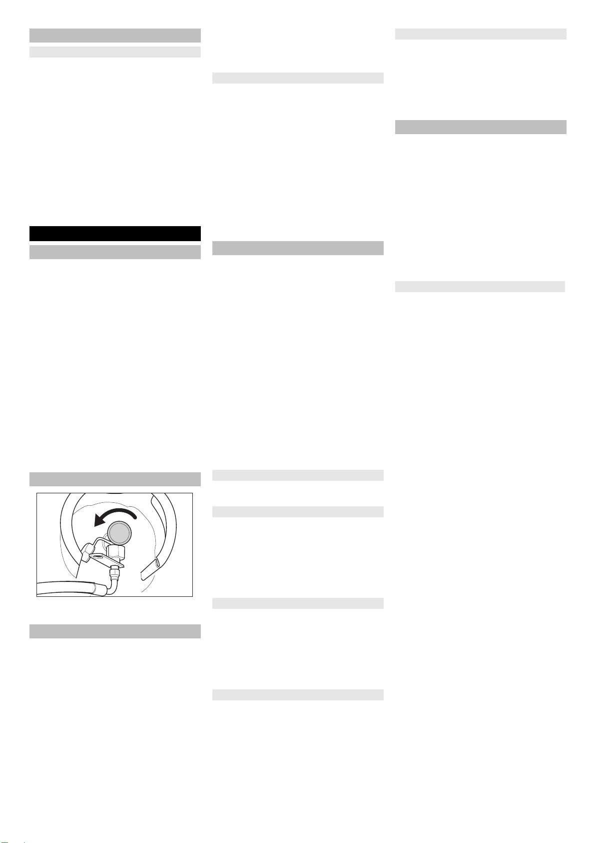
Danger
Risk of injury! Use only liquefied gas cylin-
ders with propellant filled according to DIN
51622 of A or B quality, depending on the
surrounding temperature.
CAUTION
Useofcookinggasisstrictlyprohibited.For
the gas engine, use only liquid gas mix-
tures of propane/ butane or their mixtures
where the mixing ratio lies between 90/10
to 30/70. On account of better cold start be-
haviour even at low outside sub-zero tem-
peratures (below 0° C / 32 °F) always pre-
fer a mixture with a higher propane share
because evaporation takes place even at
low temperatures.
– All persons handling liquid gases are li-
able to acquaint themselves with the
special properties of the liquefied gases
for hazard-free handling of operations.
The current documentation is always to
be kept with the sweeper.
Proper use
Foreseeable misuse
Suitable surfaces
Safety instructions
Safety instructions concerning the
operation
Safety information concerning the
driving operation
Safety regulations for LPG vehicles
Liabilities of the factory management
and the employee
20 EN

-3
– Propellant-operated units are to be
checked at regular intervals, at least
once a year, by an expert against leaks
(according to BGG 936) and ensure
that the unit is functioning properly.
– The inspection must be certified and
documented. The inspection guidelines
are § 33 and § 37 UVV (occupation ac-
cident prevention regulations) "Use of
liquid gas" (BGV D34).
– General applicable regulations are the
guidelines for inspecting vehicles
whose engines are driven by liquefied
gases of the Federal Transportation
Minister.
– Gas must always be drawn only from
one cylinder. Drawing gas from multiple
cylinders simultaneously can cause liq-
uid gas from one cylinder flowing into
the other. This causes the over-filled
cylinder to be subjected to an unpermit-
ted excess pressure when the cylinder
valve is closed later (refer B.1 of these
guidelines).
– Note the installation position of the gas
connection during installation of the full
bottle, further information in chapter “In-
stalling the gas bottle”.
Perform the replacement of the gas cylin-
der carefully. During assembly and disas-
sembly, the gas outlet nozzle of the cylin-
der valve must be sealed by means of a
cap nut that is tightened using a wrench.
– Discontinue the use of leaky gas cylin-
ders. Such cylinders are to be emptied
by slowly letting out the gas in open
spaces by conforming to all safety reg-
ulations and are to be indicated as
leaky. Also inform the issuing company
or its representative (the filling-station
attendant) in writing about the damage
to the cylinder while delivering or re-
ceiving the cylinders.
– Before connecting the gas cylinder,
check that its connection neck is in a
proper state.
– After connecting the cylinder, regularly
check that it is not leaky by using a
foaming agent.
– Open the valves slowly. Do not use
hammers to open and close the cylin-
ders.
– Fight liquid-gas fires only from a safe
distance and with protection.
- use only dry powder carbon dioxide
extinguishers or carbon dioxide gas ex-
tinguishers.
- use abundant water to cool the gas
tank.
– The entire LPG unit must be continu-
ously checked to ensure that there are
no leaks and the unit is functioning
properly. Using the vehicle with a leaky
gas unit is strictly prohibited.
– First close the cylinder valve before
loosening the pipe or tube connection.
Unscrew and loosen the connection nut
of the gas cylinder slowly because oth-
erwise the gas under pressure in the
tube will flow out instantly.
– If the gas is refilled from a larger tank,
then ask the sales agent of the LPG
about the important regulations to be
followed.
Danger
Risk of injury!
–LPG in a liquid state can cause frost
bites on bare skin.
–Afterdisconnectingthe cylinder,tighten
the closing nut firmly on the connecting
threading of the cylinder.
–Use soap water or some such foaming
agent to check whether the cylinder is
leaking. The use of open flames to illu-
minate the LPG unit is strictly prohibit-
ed.
–Follow the manufacturer's installation
specifications while changingindividual
parts of the LPG unit. Close all cylinder
and locking valves while doing so.
–Regularly check the status of the elec-
trical unit of the LPG vehicles . Sparks
can cause explosions if the gas-carry-
ing parts of the unit are leaky.
–If a LPG-driven vehicle has been idling
for a long time, then first ventilate the
setting room before commissioning the
vehicle or its electrical unit.
–Immediately inform the trade associa-
tion and the concerned trade superviso-
ry authority about accidents with gas
cylinders or LPG units. Store the dam-
aged parts carefully until all investiga-
tions have been completed.
– Propellants or LPG cylinders must al-
ways be stored according to the regula-
tions of TRF 1996 (Technical Regula-
tions for Liquid Gases, refer DA to BGV
D34, Appendix 4).
– Always store the gas cylinders in a ver-
tical position. Use of open flames and
smoking at the installation site of the
cylinders and during repairs is strictly
prohibited. Protect the stored cylinders
against unauthorised access. Close all
empty cylinders properly.
– Close the cylinder and main locking
valves immediately when you switch off
the vehicle.
– Follow the regulations for garages and
the construction guidelines of the re-
spective State about the location and
structure of the parking areas for LPG-
driven vehicles.
– Gas cylinders are to be stored in sepa-
rate rooms away from the parking areas
(refer DA to BGV D34, Appendix 2).
– The electrical hand-held lamps used in
the rooms are to be equipped with
closed, sealed case and a strong pro-
tection cover.
– Close all cylinder and main valves be-
fore working in repair workshops and
protect the gas cylinders against effect
of external heat.
– A responsible person must check that
all valves, especially the cylinder
valves, are closed during operational
breaks and before closing the factory.
Do not carry out any jobs involving fire -
such as cutting and welding jobs - in the
vicinity of the gas cylinders. Do not
store gas cylinders, not even empty
ones, in the workshops.
– The parking and storage rooms and the
repair workshops must be ventilated
properly. Please note that liquefied gas-
es are heavier than atmospheric air.
They get collected on the floor, in re-
cesses and other holes in the floors and
form a gas-air mixture that can lead to
explosions.
Do not use the device at elevations of
over 1200 m.
DANGER
Risk of poisoning!
(Gas motor)
The device is permitted for operation in
confined spaces with sufficient ventila-
tion.
(Applicable for Germany only)
In Germany, the operation of gas motor
devices in confined spaces is prohibit-
ed.
Exhaust gases are poisonous and haz-
ardous to health, do not inhale them.
DANGER
Risk of injury!
The exhaust gas opening of the com-
bustion engine must not be closed.
The motor requires approx. 3 seconds
to come to a standstill once it has been
switched off. During this time, stay well
clear of the drive area.
DANGER
Risk of burns!
Do not touch hot combustion engine.
Allow the vehicle to cool down before
removing the panels.
Do not bend over the exhaust or touch
it.
DANGER
Risk of injury!
When working on the high emptying
system, completely lift and secure the
waste container.
Perform the safeguarding only from
outside the hazard zone.
Maintenance by expert
Commissioning/Operations
In the installation and storage rooms as
well as the workshops
Appliances with combustion engine
Appliances with high emptying
system
21EN

-4
NOTICE
The overhead guard (optional) protects the
driver against larger falling objects. Howev-
er, it does not provide rollover protection!
Check the overhead guard for damage
daily.
If the overhead guard, as well as indi-
vidual elements, should be damaged,
replace the entire overhead guard.
Any modification of the overhead guard
and installation of elements, compo-
nents and assemblies other than those
approved by ISAL is not permitted and
may limit the function of the overhead
guard.
Observe the net weight (transport
weight) of the device during transport
on trailers or vehicles.
Disconnect the battery and securely
fasten the device for transport.
First switch off the appliance and re-
move the key before performing any
cleaning or maintenance tasks on the
appliance, replacing parts or switching
over to another function.
Always disconnect the battery when
working on the electrics.
To do this, first disconnect the negative
terminal and then the positive terminal.
Reconnection is performed in reverse
sequence. Connect the positive termi-
nal first, then connect the negative ter-
minal.
Do not clean the appliance with a water
hoseorhigh-pressure waterjet(danger
of short circuits or other damage).
Maintenance work may only be carried
out by approved customer service out-
lets or experts in this field who are famil-
iar with the respective safety regula-
tions.
Please observe the local safety regula-
tions regarding portable commercially
used appliances.
Always use appropriate gloves while
working on the device.
The sweeper operates using the sweep-
shovel principle.
– The rotating roller brush moves the dirt
directly into the waste container.
– The side brush cleans the corners and
edges of the surface and moves dirt
and debris into the path of the roller
brush.
– The fine dust is sucked in via the dust
filter through the suction blower.
DANGER
Risk of personal injury or damage!
Observe the weight of the appliance
when you load it!
Do not use a fork lift, the appliance
could get damaged.
Use a suitable ramp or a crane to load
the appliance!
Observe when using a ramp:
Ground clearance 70 mm.
If the machine is delivered on a pallet,
you must create an unloading ramp us-
ing the boards provided.
You will find the instructions for this pro-
cedure on page 2 (inside of cover).
Important instruction: every board
must be attached with at least 2 screws.
Devices with overhead guard
Safety information concerning the
transport of the appliance
Safety information concerning
maintenance and care
Function
Unloading tips
Net weight (transport weight) 851 kg*
* If upgrade kits are installed, the weight is
respectively higher.
22 EN

-5
Illustration
1 Nameplate
2 Seat (with seat contact switch)
3 Steering wheel
4 Centrifugal separator
5 Lock of appliance hood
6 Cover
7 Side brush, right
8 Front wheel
9 Roller brush access
10 Lashing point
11 Beacon lamp
12 Appliance cover right side
13 Cover, right
14 Gas cylinder
15 Safety rod
16 Tail panel
17 Rear wheel
18 Cover, left
19 Bonnet left side (engine bonnet)
Illustration
1 Roller brush and side brush control le-
ver
Lever forwards: Switches the roller
brush on and lowers and switches the
side brushes on.
Lever backwards: Switches the roller
brush on
2 Control lever waste container
Raise/lower waste container
3 Roller brush control lever
Raises and lowers the roller brush
4 Control lever container flap
Open/close container lid
5 Indicator lamps and display
6 Switch blower and filter cleaning
Position centred: Filter cleaning and
blower off
Front position: Blower on
Rear position: Filter cleaning on and
blower off
7 Horn switch
8Fuses
9 Ignition lock
Position 0: Switch off engine
Position 1: Ignition on
Position 2: Start the engine
10 Gas lever
Motor speed adjustment
11 Parking brake
12 Roller brush wear adjustment / sweep-
ing area setting
13 Choke
Illustration
1 Brake pedal
2 Accelerator pedal, "forwards"
3 Accelerator pedal, "reverse"
Operating and Functional Elements
Illustration of sweeper Operating field
Pedals
23EN

-6
Illustration
1 Operating hour counter
2 Charge warning lamp
3 Oil pressure warning lamp
4 Cooling water temperature warning
lamp
5 Motor suction air
6 Warning light parking brake operated
7 Forward travel direction
8 Direction of travel reverse
9 Indicator light parking light/low beam
(option)
10 Warning lamp fuel reserve
- blinks for reserve
- illuminates when gas bottle is empty
Loosen parking brake; press brake
pedal at the same time.
Activate the parking brake; press brake
pedal at the same time.
Note
This procedure is necessary if the device
needs to be pushed off the palette or towed
away, or must be moved onto a transport
vehicle without its own drive.
ATTENTION
Do not move the machine for long distanc-
es without engaging self-propulsion; a
speed of 10 km/h should not be exceeded.
1Screw
2Key
Unscrew the screw.
Remove the spanner.
1 Hydraulic pump
2Key
3Nut
Loosen the nut using the spanner (open
freewheel) until the device can be
pushed.
IMPORTANT: Once pushed, reclose
the nut (close freewheel = drive posi-
tion).
Read the operating instructions of the
engine manufacturer before start-up
and follow the safety instructions care-
fully.
Park the sweeper on an even surface.
Remove ignition key.
Lock parking brake.
몇Warning
Only use replacement cylinders with 11 kg
contents of tested models.
Danger
Risk of injury!
–Follow safety regulations for LPG vehi-
cles.
–Formation of crusts and yellow-frothing
deposits on the gas cylinder indicate
leakiness.
–Cylinders must be changed only by in-
structed persons.
–Cylinders containing propellant gases
must not be changed in garages and
underground areas.
–Do not smoke and use uncovered light
while changing the cylinder.
–While changingcylinders,first close the
locking valve of the LPG cylinder firmly
and immediately put the protective cap
on the empty cylinder.
ATTENTION
Observe the installation position of the gas
cylinder. The connection / ring opening
must point downwards.
1 Gas cylinder
2 Safety rod
3 Bracket closure
Release the screws on the safety rod
and pivot the pole away.
Replace the gas cylinder.
Unscrew the protective cap from the
connecting valve of the gas cylinder.
Close the bracket closure.
ATTENTION
After connecting the cylinder, regularly
check that it is not leaky by using a foaming
agent.
1 Protective cover
2 Gas hose with union joint
3 Gas withdrawal valve
Screw the gas hose to the connecting
valve of the gas cylinder (30-mm span-
ner).
Close the safety bar, and secure it with
a bolt.
If the warning indicator for reserve fuel
shows an empty gas bottle continuously
during operation, proceed as follows:
Close gas drawing valve by turning it in
clock-wise direction.
Stop the the machine and continue to
run it at idle speed until the motor shuts
off.
Note: This will ensure that all gas lines
are empty and that there can be no ic-
ing which would hinder starting the mo-
tor.
Unscrew the gas hose (30-mm span-
ner).
Screw the protective cap onto the con-
necting valve of the empty gas cylinder.
Open the cliplock.
NOTICE
Connection has a left threading.
몇Warning
Open the gas drawing valve (3) only after
starting the appliance (refer chapter Start-
ing the appliance).
Indicator lamps and display
Before Startup
Lock/ release parking brake
Moving sweeper without engaging
self-propulsion
Start up
General notes
Install/replace gas bottle
Installing the gas bottle
Connecting gas cylinder
Replacing the empty gas bottle
24 EN

-7
Check engine oil level.
Check the filling level in the coolant ex-
pansion tank.
Check the sweeping roller and the side
brush for wear and wrapped belts.
Check the wheels for tied up belts.
Check the centrifugal separator and the
air filter, clean if required.
Check function of all operator control el-
ements.
Check appliance for damages.
Clean the dust filter with the filter clean-
ing button.
Note: For description, see section on Care
and maintenance.
1 Lever for seat adjustment
2 Driver seat
Pull seat adjustment lever outwards.
Slide seat, release lever and lock in
place.
Check that the seat is properly locked in
position by attempting to move it back-
wards and forwards.
Open the gas drawing valve by turning
it in anti-clockwise direction.
Note: The machine is equipped with a seat
contact switch If the driver's seat is vacat-
ed, the machine is switched off.
Sit on the driver's seat.
Lock parking brake (11).
Push motor speed adjustment (10) 1/3
to the front.
Press the brake pedal in order to start
the engine.
During cold exterior temperatures: Pull
the choke (13).
Turn the ignition switch to the right and
start the device.
If the machine starts, release the igni-
tion key.
If the motor runs smoothly, push in the
choke.
Note: Never operate the starter motor for
longer than 10 seconds. Wait at least 10
seconds before operating the starter motor
again.
1 Brake pedal
2 Accelerator pedal, "forwards"
3 Accelerator pedal, "reverse"
Push the motor speed adjustment all
the way to the front (operating speed).
Press brake pedal and keep it de-
pressed.
Release parking brake.
Press slowly the accelerator pedal "for-
ward".
DANGER
Risk of injury!
When reversing, there must not be any
risk for third parties, have somebody
marshal the driver if necessary.
Press slowly the accelerator pedal "re-
verse".
The accelerator pedal can be used to
vary the driving speed infinitely.
Avoid sudden operation of the pedal as
this may damage the hydraulic system.
In the event of power loss on inclined
surfaces, slightly reduce the pressure
on the accelerator pedal.
Release the accelerator pedal, the ma-
chine brakes automatically and stops.
Note: The braking effect can be supported
by pressing the brake pedal.
Driving over fixed obstacles which are 70
mm high or less:
Drive forwards slowly and carefully.
Driving over fixed obstacles which are
more than 70 mm high:
Only drive over these obstacles using a
suitable ramp.
ATTENTION
Do not sweep up packing strips, wire or
similar objects as this may damage the
sweeping mechanism.
Note: To achieve an optimum cleaning re-
sult, the driving speed should be adjusted
to take specific situations into account.
Note: During operation, the dust filter
should be shaken off and cleaned at regu-
lar intervals.
Note: When frequently working in areas
with fine dust, the filter must be cleaned
more often.
1 Roller brush and side brush control le-
ver
2 Control lever waste container
3 Roller brush control lever
4 Control lever container flap
Roller brush and side brush control le-
ver
Control lever (1) forwards: Switches the
roller brush on and lowers and switches
the side brushes on.
Control lever (1) backwards: Switches
the roller brush on.
Control lever waste container
Control lever waste container (2) to the
front: Waste container is lowered.
Control lever waste container (2) to the
back: Waste container is raised.
Control lever roller brush
Roller brush control lever (3) forwards:
Raises the roller brush.
Roller brush control lever (3) back-
wards: Lowers the roller brush.
Control lever container flap
Control lever container flap (4) to the
front: The container flap of the waste
container opens.
Control lever container flap (4) to the
back: The container flap of the waste
container closes.
Inspection and maintenance work
Daily before starting operations
Operation
Adjusting driver's seat
Open the gas supply
Starting the machine
Start the engine
Drive the machine
Drive forward
Reverse drive
Driving method
Brakes
Driving over obstacles
Sweeping mode
Control lever
25EN

-8
Switch on the blower.
With surface cleaning:
Roller brush and side brush control le-
ver (1) backwards: Switches the roller
brush on.
Roller brush control lever (3) back-
wards: Lowers the roller brush.
Control lever container flap (4) to the
front: Container flap opens.
With cleaning of side edges:
Roller brush and side brush control le-
ver (1) forwards: Switches the roller
brush on, switches the side brushes on
and lowers them.
Roller brush control lever (3) back-
wards: Lowers the roller brush.
Switch off the blower.
With surface cleaning:
Roller brush and side brush control le-
ver (1) backwards: Switches the roller
brush on.
Roller brush control lever (3) back-
wards: Lowers the roller brush.
Control lever container flap (4) to the
front: Container flap opens.
With cleaning of side edges:
Roller brush and side brush control le-
ver (1) forwards: Switches the roller
brush on, switches the side brushes on
and lowers them.
Roller brush control lever (3) back-
wards: Lowers the roller brush.
DANGER
Risk of injury!
During the emptying process, persons
and animals must not stay within the
swivelling range of the waste container.
Danger of tipping!
Place the device on an even surface
during the emptying process.
몇WARNING
Risk of crushing!
Never reach into the rod assembly for
the drainage mechanism. Do not stay
under the raised container.
ATTENTION
Risk of personal injury or damage!
Material of the rotating roller brush may
be catapulted off during the emptying
process. Keep an appropriate distance.
Raise the roller brush and side brushes
using the control levers: Control lever 1
to middle position and control lever 3
forwards.
Close the container flap, in order to do
so, move the control lever (4) to the
back:
Raise the container flap, in order to do
so, move the waste container control le-
ver (2) to the back:
Slowly drive towards the collection con-
tainer.
Lock parking brake.
Open the container flap, in order to do
so, push the container flap operating le-
ver (4) to the front and empty the waste
container.
Close the container flap, in order to do
so, push the container flap operating le-
ver (4) to the back until it is tipped in-
wards in the end position.
Release parking brake.
Drive away the collection container
slowly.
Lower the waste container into the end
position, in order to do so, move the
waste container control lever (2) to the
front
Raise the roller brush and side brushes
using the control levers: Control lever 1
to middle position and control lever 3
forwards.
Close the container flap, in order to do
so, move the control lever (4) to the
back:
Pull the motor speed adjustment all the
way to the back.
Press brake pedal and keep it de-
pressed.
Lock parking brake.
Turn ignition key to "0" and remove it.
DANGER
Transport damage!
Observe the net weight (transport
weight) of the device during transport
on trailers or vehicles.
When transporting in vehicles, secure
the appliance according to the guide-
lines from slipping and tipping over.
Turn ignition key to "0" and remove it.
Close gas drawing valve by turning it in
clock-wise direction.
Lock parking brake.
Secure the appliance at the lashing
points (4x) using tension belts, ropes or
chains.
Secure the wheels of the machine with
wheel chocks.
DANGER
Risk of injury and damage! Note the weight
of the appliance in case of storage.
Park the sweeper on a level surface in
a dry, frost protected area. Protect it
against dust by means of covering ma-
terial.
Raise the roller brush and the side-
brushes to prevent the bristles from be-
ing damaged.
Close the container flap.
Turn ignition key to "0" and remove it.
Close gas drawing valve by turning it in
clock-wise direction.
Unscrew the gas hose with union nut
(use 30 mm spanner).
Lock the gas bottle with the safety cap
and store upright in a suitable storage
area (also see Chapter "Safety instruc-
tions).
Lock parking brake.
Lock the sweeper to ensure that it does
not roll off.
Additionally observe the following points if
the sweeper is not used over a longer peri-
od of time:
Change engine oil.
Drain off the cooling water if frost is ex-
pected and check whether there is ade-
quate anti-frosting agent.
Clean the inside and outside of the
sweeper.
Disconnect battery.
Charge battery and recharge it approx.
every 2 months.
Sweeping dry floors
Sweeping damp or wet floors
Emptying waste container
Turn off the appliance
Transport
Storage/decommissioning
26 EN

-9
ATTENTION
Risk of damage!
Do not rinse out the dust filter.
Maintenance work may only be carried
out by approved customer service out-
lets or experts in this field who are famil-
iar with the respective safety regula-
tions.
Always disconnect the battery when
working on the electrics.
Mobile appliances used for commercial
purposes are subject to safety inspec-
tions according to VDE 0701.
Park the sweeper on an even surface.
Turn ignition key to "0" and remove it.
Lock parking brake.
Close the gas inlet.
CAUTION
Risk of damage!
Do not clean the appliance with a water
hoseorhigh-pressure waterjet(danger
of short circuits or other damage).
DANGER
Risk of injury!
Wear dust mask and protective gog-
gles.
Clean machine with a cloth.
Blow through machine with com-
pressed air.
Clean the machine with a damp cloth
which has been soaked in mild deter-
gent.
Note: Do not use aggressive cleaning
agents.
Note: The elapsed-time counter shows the
timing of the maintenance intervals.
Note: If maintenance is carried out by the
customer, all service and maintenance
work must be carried out by qualified staff.
An ISAL specialist dealer can be consulted
at any time if needed.
Daily maintenance:
Check engine oil level.
Check the filling level in the coolant ex-
pansion tank.
Check the sweeping roller and the side
brush for wear and wrapped belts.
Check the centrifugal separator and the
air filter, clean if required.
Check function of all operator control el-
ements.
Check appliance for damages.
Weekly maintenance:
Check gas lines, connections and joints
Clean the water cooler.
Clean the hydraulic oil cooler.
Check hydraulic unit.
Check the hydraulic oil level.
Check brake fluid status.
Check the pad for wear, replace if re-
quired.
Check the container lid and lubricate it.
Maintenance following wear:
Replace sealing strips.
Readjust the side seals or replace
them.
Replace roller brush.
Replace side brush.
Note: For description, see section on Main-
tenance work.
Note: In order to preserve warranty claims,
all servicing and maintenance work during
the warranty period has to be performed by
an authorised ISAL Customer Service, in
accordance with the inspection check list.
Maintenance to be carried out after 50
operating hours:
Have the first maintenance performed
by the customer service in accordance
with the inspection check list.
Maintenance after 250/500/1000/1500/
2000 operating hours:
Have the maintenance performed by
the customer service in accordance
with the inspection check list.
Preparation:
Park the sweeper on an even surface.
Turn ignition key to "0" and remove it.
Lock parking brake.
Close the gas inlet.
DANGER
Risk of injury!
Always apply the safety rod when the
waste container is raised.
Perform the safeguarding only from
outside the hazard zone.
1 Holder of safety rod
2 Safety rod
Fold the safety rod for the high empty-
ing up and insert it into the holder (se-
cured).
Please observe the following warning notes
when handling batteries:
DANGER
Risk of explosion!
Only use batteries with terminal cover.
Restore terminal cover in the event of
loss.
DANGER
Risk of explosion!
Do not place tools or similar items on
the battery. Risk of short-circuit and ex-
plosion.
DANGER
Risk of injury!
Ensure that wounds never come into
contact with lead. Always clean your
hands after working on batteries.
DANGER
Risk of fire and explosion!
Smoking and naked flames are strictly
prohibited.
Rooms where batteries are charged
must have good ventilation because
highly explosive gas is emitted during
charging.
DANGER
Danger of causticization!
Rinsethoroughlywithlotsofclearwater
if acid gets into the eye or comes in con-
tact with the skin.
Then consult a doctor immediately.
Wash off the acid If it comes in contact
with the clothes.
Care and maintenance
General notes
Cleaning
Cleaning the inside of the machine
External cleaning of the appliance
Maintenance intervals
Maintenance by the customer
Maintenance by Customer Service
Maintenance Works
General notes on safety
Do not allow fluids such as mo-
tor oil, hydraulic oil, brake fluid,
diesel or coolant to enter the
soil. Please protect the environ-
ment and dispose of fluids in an
environmentally responsible
way.
Safety notes regarding the batteries
Observe the directions on the
battery, in the instructions for
use and in the vehicle operat-
ing instructions!
Wear an eye shield!
Keep away children from acid
and batteries!
Risk of explosion!
Fire, sparks, open light, and
smoking not allowed!
Danger of causticization!
First aid!
Warning note!
Disposal!
Do not throw the battery in the
dustbin!
27EN

-10
Normally, the machine is equipped with a
maintenance-free battery.
1 Positive terminal
2 Terminal cover
3 Negative terminal
Insert battery in battery mount.
Screw on mounts on battery base.
Connect pole terminal (red cable) to
positive pole (+).
Connect pole terminal to negative pole
(-).
Attach the pole covers.
Check that the battery poles and pole
terminals are adequately protected with
pole grease.
CAUTION
Risk of damage!
Regularly check the fluid level in acid-
filled batteries.
Unscrew all cell caps.
Take a sample from each cell using the
acid tester.
– The acid in a fully charged battery has a
specific weight of 1.28 kg/l at a temper-
ature of 20 °C.
– The acid in a partially discharged bat-
tery has a specific weight between 1.00
and 1.28 kg/l.
– The specific weight of the acid must be
uniform in all cells.
Put the acid sample back into the same
cell.
Where fluid level is too low, top up cells
to the mark provided with distilled wa-
ter.
Charge battery.
Screw in cell caps.
DANGER
Risk of injury!
Comply with safety regulations on the
handling of batteries. Observe the di-
rections provided by the manufacturer
of the charger.
DANGER
Risk of damage!
Charge the battery only with an appro-
priate charger.
Unscrew all cell caps.
(only with low-maintenance battery)
Connect positive terminal cable from
the charger to the positive pole connec-
tion on the battery.
Connect negative terminal cable from
the charger to the negative pole con-
nection on the battery.
Plug in mains connector and switch on
charger.
Charge battery using lowest possible
level of charging current.
When the battery is charged, first re-
move the charger from the mains and
then disconnect it from the battery.
Screw in cell caps.
(only with low-maintenance battery)
Disconnect pole terminal to negative
pole (-).
Disconnect pole terminal to positive
pole (+).
Loosen the mounts on battery base.
Remove the battery from the battery
holder.
Dispose of the used battery according
to the local provisions.
DANGER
Risk of injury!
Always apply the safety rod when the
waste container is raised.
Perform the safeguarding only from
outside the hazard zone.
1 Holder of safety rod
2 Brake fluid container
3 Closing head
Move up the waste container and se-
cure it by means of the safety rod, see
Chapter "Emptying the waste contain-
er"
Check if the there is enough brake fluid
in the brake fluid reservoir.
Note
The filling level has to be between Min.
and Max.
If necessary, refill DOT brake fluid cur-
rently commercially available.
DANGER
Risk of burns!
Allow engine to cool down.
Wait for at least 5 minutes after switch-
ing off the engine before checking the
engine oil fill level.
1 Oil cap (engine)
2 Oil dipstick
Pull out oil dipstick.
Wipe off oil dipstick and insert.
Pull out oil dipstick.
Read the value of the oil level.
Insert the oil dip again.
– The oil level must lie between “MIN“
and “MAX“ marking.
– Add motor oil if the oil level is below the
"MIN" marking.
– Do not fill oil above the "MAX" marking.
Remove oil cap.
Fill in motor oil.
For oil type refer to Chapter "Technical
specifications".
Close oil cap.
Wait at least 5 minutes.
Check engine oil level.
CAUTION
Risk of burns due to hot engine oil!
Allow engine to cool down.
Prepare a collection container for at
least 6 litres of engine oil.
Allow engine to cool down.
Installing and connecting the battery
Check and correct the fluid level of the
battery (only with low-maintenance
battery with cell caps)
Charging battery
Remove the battery
Checking the brake fluid level and
topping up brake fluid
Check engine oil level and top up, if
required
Change the motor oil and the oil filter
28 EN

-11
1 Oil drain screw
2 Engine oil filter
Unscrew oil drain plug.
Remove oil cap.
Drain off oil.
Unscrew the oil filter.
Clean the intake and sealing areas.
Coat the washer of the new oil filter with
oil before fitting it.
Fit in the new oil filter and tighten it by
hand.
Screw in the oil drain screw along with
the new washer.
Tightening torque: 25 Nm
Fill in motor oil.
For oil type and filling quantity refer to
Chapter "Technical specifications".
Close oil cap.
Let the motor run for approx. 10 sec-
onds.
Check engine oil level.
NOTICE
The waste container must not be raised.
Open the device hood and secure it us-
ing the hood support.
1 Hydraulic oil sight glass
2 Hydraulic tank
3 Screw cap, oil fill opening
4 Hood support
Check hydraulic oil level in the looking
glass.
– The oil level must lie between “MIN“
and “MAX“ marking.
– Add hydraulic oil if the oil level is below
the "MIN" marking.
Loosen the closing cap of the oil filling
opening.
Clean the filling area.
Refill hydraulic oil.
For oil type refer to Chapter "Technical
specifications".
Replace and tighten the closing cap of
the oil filling opening.
NOTICE
Maintenance of the hydraulic system is
only to be carried out by ISAL Customer
Service.
Lock parking brake.
Start the motor.
Check all hydraulic hoses and connec-
tions and ensure that they are leak-
proof.
1 Coolant expansion tank
Check filling level while the motor is
cold.
Check the filling level in the coolant ex-
pansion tank.
The correct coolant level has to be be-
tween MIN and MAX.
DANGER
Risk of burning and scalding!
Allow the water cooler to cool down for
at least 20 minutes.
The coolant level of the water cooler is
checked at the coolant expansion tank.
See chapter "Checking the cooling wa-
ter level".
Clean cooler lamella.
Remove soiling by means of a soft
brush, compressed air or low water
pressure.
Check cooler hoses and connections
and ensure that they are leak-proof.
Clean the fan.
Start the motor.
Raise the waste container up to the
end-position.
Switch off engine.
Lock parking brake.
Use the safety bar for emptying from a
height.
Remove belts or cords from roller
brush.
Remove the safety bar.
Start the motor.
Lower the waste container up to the
end-position.
Switch off engine.
1Key
2 Side panels
Drive the waste container up and sup-
port it with the safety rod.
Open the side covers using a key.
1 Holding bow
2 Wing nut
3Side seal
Unscrew the wing nuts.
Remove the retaining clamp.
Flip the side seal out.
Uncscrew the retaining screw of the
roller brush intake, and swing the intake
to the outside.
Pull out roller brush.
Installation position of roller brush in direc-
tion of travel (top view)
Note: When installing the new roller brush,
ensure correct positioning of the bristle as-
sembly.
Install new roller brush. The nuts of the
roller brush must be inserted on the
notches of the opposite crank.
Note: Once the new roller brush has been
installed, the sweeping track must readjust-
ed.
Check hydraulic oil level and refill
hydraulic oil
Check hydraulic unit
Check coolant level
Checking and cleaning water/hydraulic
oil cooler
Checking roller brush
Replacing roller brush
29EN

-12
Note: The sweeping track is factory-set to
80 mm; it is steplessly adjustable if the
brush roller wears down.
Check tyre pressure.
Switch off suction blower.
Drive sweeper on to a smooth, even
surface covered with a visible layer of
dust or chalk.
Roller brush and side brush control le-
ver (1) backwards: Switches the roller
brush on.
Roller brush control lever (3) back-
wards: Lowers the roller brush.
Allow the roller brush to run for approx.
10 seconds.
Roller brush and side brush control le-
ver (1) to middle position.
Roller brush control lever (3) forwards:
Raises the roller brush.
Drive machine backwards.
Check sweeping mirror.
The sweeping track should have an even
rectangular shape which is 80-85 mm wide.
Undo and adjust the stop screw for
wear adjustment (12).
Stop screw at the top: narrow sweeping
area.
Stop screw at the bottom: broad sweep-
ing area.
Tighten the stop screw again.
Check the sweeping area of the roller
brush again as described.
The side-brushes lift up.
Drive sweeper on to a smooth, even
surface covered with a visible layer of
dust or chalk.
Lower the side brushes using the con-
trol lever and allow them to run for ap-
prox. 10 seconds.
The side-brushes lift up.
Drive machine backwards.
Check sweeping mirror.
The width of the sweeping track should lie
between 40-50 mm.
Set the sweeping track using the two
adjusting screws.
Check sweeping mirror.
DANGER
Risk of injury!
Always apply the safety rod when the
waste container is raised.
Perform the safeguarding only from
outside the hazard zone.
Drive the waste container up and se-
cure it with the safety rod.
Fold the safety rod for the high empty-
ing up and insert it into the holder (se-
cured).
1 Holder of safety rod
2 Safety rod
Open the side cover as described in
Chapter "Replace brush roller".
Release the 6 wing nuts on the side
holding plate.
Loosen 3 nuts (SW 13) on the front
holding plate.
Press the side seal down (elongated
hole) until it is about 1 to 3 mm to the
floor.
Screw in the holding plates.
Repeat the procedure on the other side
of the appliance.
Switch on manual filter shake off.
몇WARNING
Risk of injury!
Wear a dust mask when working
around the dust filter. Observe safety
regulations on the handling of fine parti-
cles.
Clean the dust filter with the filter clean-
ing button.
Empty waste container.
1 Lock of appliance hood
2Cover
3 Filter cover
Open the lock, remove the star grip
screw to do this.
Fold cover forwards.
1 Lock, filter cover (2x)
2 Filter cover
Open the lock.
Open filter cap.
Check and adjust roller brush sweeping
track
Check and adjust sweeping track of the
side-brush
Adjust the side seals
Manually clean the dust filter
Check/replace dust filter
2
1
30 EN

-13
1 Cross struts
2 Dust filter
Check the dust filter, clean or replace if
necessary.
Note
Exchanging the dust filter may only be
done by the ISAL Customer Service.
Insert and lock the filter cover.
The V-Belt must deflect approx. 7-9 mm at
a pressure of 10 kg.
Get the V-belt tension adjusted by an
authorized customer service.
1Lock
2 Air filter housing
Remove side panel.
Remove the air filter housing.
Replace the air filter insert.
Note: Installation position with blowout
opening pointing down (see illustra-
tion).
1 Wing nut
2 Centrifugal separator
Unscrew the wing nut from the centrifu-
gal separator.
Clean the centrifugal separator.
1 Lock nut
2 Cover fuse box
Unscrew the knurled nut.
Open the cover on the fuse box.
Check the fuses.
Replace defective fuses.
Note: Only use fuses with identical
safety ratings.
Note: The fuse FU 01 is located in the en-
gine compartment.
1 Fuse FU 01 (main fuse)
* These fuses may only be changed by
Customer Service, as it is necessary to
check the device for potential faults.
Check and adjust the V-Belt
Check air filter and replace, if necessary
Clean the centrifugal separator
Replacing fuses
FU 01* Main fuse 60 A
FU 02 Horn
Suction blower
20 A
FU 03 Multifunction display 3 A
FU 04 Beacon lamp 5 A
FU 05 Motor control unit 10 A
FU 06 Driver cabin (optional)
Wiper
10 A
FU 07 LPG filling level display 5 A
FU 08 Starter 10 A
FU 09 Left lighting 7,5 A
FU 10 Right lighting 7,5 A
FU 11 Working light 10 A
FU 12 Vibrator system 25 A
FU 13 LPG valve
Backup signal
7,5 A
31EN

- 14
Troubleshooting
Fault Remedy
Appliance cannot be started Sit on the driver seat, the seat contact switch gets activated.
Press the brake pedal in order to start the engine.
Charging or replacing battery
Gas bottle empty - replace gas bottle.
Gas removal valve closed - open the valve by turning it in anti-clockwise direction.
Gas valve iced - please read the description of the gas bottle replacement procedure.
Contact an ISAL Customer Service department
Engine is running erratically Clean air filter or change filter cartridge.
Check fuel pipes, connections and joints and maintain them if required
Checking the installation position of the gas bottle: Connection or ring opening must face down-
wards.
Contact an ISAL Customer Service department
Engine is overheated Refill coolant
Rinse cooler
Tighten V-Belt
Contact an ISAL Customer Service department
Engine is running but machine is
only moving slowly or is not moving
at all
Release parking brake
Close freewheel (drive position)
Move the gas lever all the way to the front (high speed).
Check for trapped ribbons and strings.
Contact an ISAL Customer Service department
Whistling sound in the hydraulic
system
Refill hydraulic fluid
Contact an ISAL Customer Service department
Brushes are rotating slowly or not
at all
Move the gas lever all the way to the front (high speed).
Check for trapped ribbons and strings.
Contact an ISAL Customer Service department
Too little or no suction power in the
brush area
Check dust filter, clean or replace.
Contact an ISAL Customer Service department
Dust gathers in the machine Adjust the side seals
Switch on blower
Check dust filter, clean or replace.
Replace filter washers
Open the container flap of the waste container.
Contact an ISAL Customer Service department
Sweeping unit does not pick up
waste
Empty waste container
Check dust filter, clean or replace.
Replacing roller brush
Adjust sweeping track
Replace sealing strips of the waste container
Remove the blocking of the brush roller
Open the container flap of the waste container.
Contact an ISAL Customer Service department
Waste container does not raise or
lower
Move the gas lever all the way to the front (high speed).
Remove the locking support from the waste container
Contact an ISAL Customer Service department
The container flap of the waste
container does not open.
Contact an ISAL Customer Service department
Operation problems with hydraulic
movement parts
Contact an ISAL Customer Service department
32 EN

-15
Technical specifications
120 GPL
Machine data
Drive speed, forward km/h 9
Drive speed, reverse km/h 4
Climbing capability (max.) % 18
Surface cleaning performance without side brushes m2/h 8100
Surface output with side-brush m2/h 10800
Working width without side brushes mm 900
Working width with side-brush mm 1200
Protection type, drip-proof -- IPX 3
Working time with a full gas bottle h 4
Engine
Type -- Kubota WG 972 GL-E3
Type -- 3-cylinder LPG gas motor
with a 3-way catalytic converter
Cooling type -- Water cooling
Rotation direction -- Anticlockwise direction
Holes mm 68
Hub mm 68
Cylinder capacity cm3740
Amount of oil l 3,25
Operating speed 1/min 2500
Max. speed 1/min 2500
Dry run speed 1/min 1300
Max. power kW/PS 12,7 / 17,0
Maximum torque at 2400 rpm Nm 60
Oil filter -- Filter cartridge
Suction air filter -- Internal filter cartridge, external filter car-
tridge
Fuel type Liquid gases (propellants): Butane and propane or a
mixture of butane/propane
Tank content 11 kg / 20 litres (replacement cylinder)
Electrical system
Battery V, Ah 12, 52
Generator, rotary current V, Watt 12, 150
Starter -- Electrical starter
Hydraulic system
Oil quantity in the entire hydraulic system l 26,5
Oil quantity in hydraulic tank l 21,2
Oil grades
Engine (above 25 °C) -- SAE 30, SAE 10W-30, SAE 15W-40
Engine (0 to 25 °C) -- SAE 20, SAE 10W-30, SAE 10W-40
Engine (below 0 °C) -- SAE 10W, SAE 10W-30, SAE 10W-40
Hydraulics -- HV 46
Waste container
Max. unloading height mm 1400
Volume of waste container l 250
Roller brush
Roller brush diameter mm 300
Roller brush width mm 900
Speed 1/min 350
Sweeping track mm 80
Side brushes
Side brush diameter mm 600
Speed (continuous) 1/min 0 - 60
33EN

-16
We hereby declare that the machine de-
scribed below complies with the relevant
basic safety and health requirements of the
EU Directives, both in its basic design and
construction as well as in the version put
into circulation by us. This declaration shall
cease to be valid if the machine is modified
without our prior approval.
The undersigned act on behalf and under
the power of attorney of the company man-
agement.
Solid rubber tyres
Size, front -- 15-4.5x8
Size, rear -- 15-4.5x8
Brake
Front wheels -- mechanical
Rear wheel -- hydrostatic
Filter and vacuum system
Type -- Pocket filter
Speed 1/min 2800
Filter surface area, fine dust filter m26,0
Nominal vacuum, suction system mbar 15,5
Nominal volume flow, suction system m3/h 800
Vibrator system -- Electric motor
Working conditions
Temperature °C -5 and +40
Air humidity, non-condensing % 0 - 90
Values determined as per EN 60335-2-72
Noise emission
Sound pressure level LpA dB(A) 83
Uncertainty KpA dB(A) 3
Sound power level LWA + Uncertainty KWA dB(A) 104
Machine vibrations
Hand-arm vibration value m/s2<2,5
Seat m/s20,8
Uncertainty K m/s20,1
Dimensions and weights
Length x width x height mm 2082x1250x1450
Right turning radius mm 1350
Left turning radius mm 1350
Unladen weight kg 851
Permissible overall weight kg 1300
Permissible front axle load kg 787
Permissible rear axle load kg 513
Subject to technical modifications!
120 GPL
EU Declaration of Conformity
Product: Ride-on vacuum sweeper
Type: 120 GPL
S/N 0110137
Relevant EU Directives
2006/42/EC (+2009/127/EC)
2014/30/EU
2000/14/EC
Applied harmonized standards
EN 60335–1
EN 60335–2–72
EN 55012: 2007 + A1: 2009
EN 61000–6–2: 2005
EN 62233: 2008
Applied conformity evaluation method
2000/14/EC: Appendix V
Sound power level dB(A)
Measured: 102
Guaranteed: 104
34 EN
ISAL s.r.l. con Unico Socio
Via P.Colletta, 19
42124 REGGIO EMILIA - ITALY
fon. +39 0522 823011
fax. +39 0522 823030
Other manuals for PB120LPG
1
Table of contents
Other CONQUEST Blower manuals
Popular Blower manuals by other brands

Master cool
Master cool 1200 CFM Blower Fan instruction manual

Ebmpapst
Ebmpapst G2S076-AA03-01 operating instructions

Ebmpapst
Ebmpapst R2E250-RA50-09 operating instructions

Silvercrest
Silvercrest SABD 3.6 Li B1 operating instructions

sunjoe
sunjoe SBJ802E-RM Operator's manual

FLORABEST
FLORABEST FBLB 33 A1 Operation and safety notes