manuals.online logo
Brands
  1. Home
  2. •
  3. Brands
  4. •
  5. Conrad-Johnson
  6. •
  7. Amplifier
  8. •
  9. Conrad-Johnson PV10A User manual

Conrad-Johnson PV10A User manual

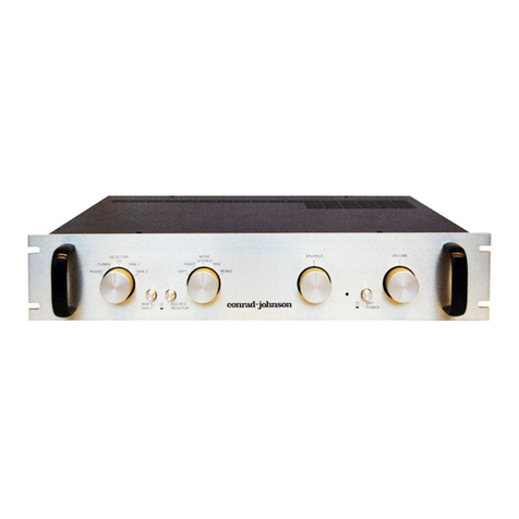
Thank you for selecting the PV10A as the control center for your audio
system. The PV10A draws on two decades of research at conrad-
johnson into the reproduction of recorded music. The result is a line-
stage preamplifier with a remarkable ability to recreate the the
dynamics, textures, tonalities, and ambience of live musical perform-
ances. With the PV10A, we believe that you will experience the excite-
ment of discovery in hearing more from your favorite recordings than
ever before.
Atconrad-johnson,weexpectourproductstobeasourceofsatisfaction
and of pride to their owners for many years to come. Accordingly, circuit
designs, parts and materials for all conrad- johnson products are se-
lected with a view to maintaining optimal performance over the years.
Our reputation for producing among the industry’s most reliable compo-
nents is a natural consequence of this engineering approach.
Although the PV10A has been designed to operate in an intuitively
apparent way, you will find useful information on it’s installation and
operation in this manual. Please take a few minutes to read the manual
to better understand the features and capabilities of your PV10A. Note
that the line-stage section of this unit is phase inverting. See the section
entitled "Getting The Most From Your PV10A" for details on correct
hookup in your system.
In closing, we’d like to welcome you to the family of conrad-johnson
owners. We want you to enjoy your conrad-johnson product to the
fullest. To this end, our staff stands ready to answer any questions you
may have about the function and application of your PV10A, and to
provide any needed service both during, and after the warranty period.
Our goal is to heighten your enjoyment of recorded music.
PV10A Owner’s Manual 1
Limited Warranty For Conrad-Johnson Components
conrad-johnson design, inc. will provide service under warranty to the
original owner on products sold new in the United States for the lesser
period of three years from the date of purchase by the original pur-
chaser, or five years from the date of shipment to the authorized
conrad-johnson dealer. During the warranty period, conrad-johnson will
repair defective units without charge for labor or parts (with the excep-
tion of vacuum tubes and batteries).
Exclusions. The following are not covered under this warranty:
a) Units which have been damaged by misuse, abuse, or accident.
b) Units which have been modified, altered, or improperly repaired by
anyone not specifically authorized by conrad-johnson design, inc.
c) Units not purchased from an authorized conrad-johnson dealer in the
United States for use in the United States.
d) Normal wear.
e) Incidental or consequential damages are not covered under this
warranty. Some states do not allow the exclusion of incidental or
consequential damages, so this exclusion may not apply to you.
Obtaining Warranty Service: To obtain warranty service, the unit must
be shipped, along with evidence of purchase, in factory packing to
conrad-johnson design (or designated service center) with freight and
insurance prepaid by the owner. After repair, the unit will be returned
with freight and insurance prepaid by conrad-johnson design to any
destination in the United States.
All implied warranties, including merchantability and fitness for a par-
ticular purpose are limited in duration to the duration of this p73 express
warranty. Some states do not allow limitations on the duration of implied
warranties so the above limitations may not apply to you.
This warranty gives you specific legal rights and you may also have
other rights which vary from state to state.
Conrad-Johnson products purchased outside the United States are
covered by warranty terms of the importing distributor in the country in
which the product was originally purchased, which may differ from the
terms set out herein. Importing distributors are not obligated to provide
warranty service for products originally purchased outside their country.
Conrad-Johnson will provide warranty service for products outside the
PV10A Owner’s Manual 2
United States, but the customer must pay all shipping, handling and
customs costs both to and from our Service Department.
Questions about this warranty should be addressed to:
Service Department
conrad-johnson design, inc.
2733 Merrilee Drive
Fairfax, VA 22031
The Service Department can also be reached by phone at 703-698-
8581, or by fax at 703-560-5360
Service
If your conrad-johnson audio component requires service, repack it
using the original box and packing material and ship to the Service
Department address above. Boxes and packing materials can be ob-
tained from our service department for a nominal charge, if you no
longer have yours. Include with the unit a note describing the problem
you are having in as much detail as possible. It is especially important
for our technician to know if the problem is intermittent. If you want an
estimate of cost for out of warranty service, be sure to request it in this
note.Beawarethatrequestinganestimatewilldelayservicetoyourunit
as we will have to contact you for your approval before commencing
service.
Registering The Warranty
Please return the enclosed card to the factory within 30 days of pur-
chase to register the warranty.
PV10A Owner’s Manual 3
Installation
The PV10A dissipates up to 35 watts of heat, and must be adequately
ventilated. Mount the unit horizontally on a flat, hard surface, and take
care that the ventilation holes in the bottom are unobstructed. Allow at
least two inches of clearance above the unit and keep the cabinet or
shelf open at the back. Vertical installation is not recommended.
All PV10As sold in the United States are configured for operation on a
60Hz ac power line producing between 108 and 126 volts. Export
versions will have the correct operating voltage and frequency clearly
marked on the back panel of the unit, near the ac power cord. In all
cases, the actual line voltage should be within + 5/- 10% of the nominal
rated voltage.
Electromagnetic Interference (EMI)
Considerable care has been taken in the design of the PV10A to
minimize it’s susceptibility to radio frequency interference and other
forms of EMI. Choice of materials, physical layout, grounding practice,
andpower supply design haveall been specified witha view to reducing
the impact of electromagnetic fields on the performance of this unit. At
the same time, however, our primary goal is the accurate reproduction
of recorded music in the normal home environment, and we have
elected not to compromise this objective by the application of heavy-
handed RFI filters, or by using grounding practices that reduce RFI at
theexpense of degraded audioperformance. We find thatthe approach
we have taken has worked extremely well, resulting in only rare in-
stances of EMI problems which could be treated locally as needed,
rather than compromising the performance of our product in the 99.9%
of installations where EMI is not a problem.
CareininstallationcanoftenavoidEMIinducedproblems.Thefollowing
practices should generally be observed in any application, and will be
especially important where EMI may be a problem.
Interconnect cables should be kept as short as possible (3 meters or
less), and shielded cable should be used (cable which has two center
conductors, and a separate external shield connected at only one end).
PV10A Owner’s Manual 4
Physical location and cable "dress" can be an important factor in
minimizing hum pickup. The installation should situate the preamplifier
well away from the power amplifier, and power (ac mains) cords should
be dressed to remain at least 4" (100mm) away from input/output
cables.
Connection
AUX1/PH: On a PV10AL, this is an additional line-level input, and is
identical to the other inputs. On a PV1OA with phono stage, this input
provides the amplification and equalization required by moving magnet
and high output moving coil cartridges. The phono input impedance is
the industry standard 47,000 ohms shunted by approximately 100 pico-
farads capacitance. This is well suited to nearly all moving magnet and
many high-output moving coil cartridges. If necessary, the input imped-
ance can be lowered by soldering a resistor across ( from center pin to
ground) the input jack. To achieve a desired input resistance of RD, use
the following formula to compute the required additional resistance RA:
RA = (47000 x RD)/(47000-RD)
Some moving magnet cartridges require higher capacitance for opti-
mum performance. Increasing the input capacitance may be achieved
by soldering a suitable value capacitor across the phono input jack. Use
polystyrene capacitors for this purpose.
TUNER, CD, VIDEO, AUX2, TAPE IN: These are high level inputs and
are electrically equivalent. They present a 50k ohm load to the source.
The outputs of your tape recorders should be connected to "TAPE IN".
TAPEOUT: This output connects the selected signal to your recorder or
external processing loop (eg. equalizer). The output signal is not af-
fected by the level control. Connect "TAPE OUT" to the inputs of your
tape recorder or external processor.
MAIN OUT: Connect this output to the input of your amplifier(or cross-
over in a bi-amped system). We recommend the use of an amplifier with
an input impedance of 10k ohms or higher. Since the PV10A inverts
phase, it may be necessary to invert the speaker leads to maintain
correct phase. See the section on "Getting the most out of your PV10A"
for an explanation of this.
PV10A Owner’s Manual 5
EXTERNAL TONE CONTROLS OR OTHER SIGNAL PROCESSING
DEVICES: Connect the output from your processor to the TAPE IN
input, and the input of your processor to the TAPE OUT output on the
PV10A. The TAPE MON position of the SOURCE/TAPE MON button
will insert the processor into the circuit; the SOURCE position will
provide flat, unprocessed response.
PV10A Owner’s Manual 6
CONTROLS
OFF, ON: Because of the delayed warmup characteristics of vacuum
tube equipment, a time delay muting circuit is incorporated in this
preamplifier. The MAIN OUT connections are grounded via a relay for
approximately90secondsafterthe unit is turned oninordertosuppress
warm-up transient noises. The relay grounds the outputs again immedi-
ately at turn off or in the event of any power line interruption.
SELECTOR: This switch is used to choose among AUX1/PHONO,
TUNER, CD, VIDEO, and AUX2 inputs. The selected source will be
available at the source position of the tape monitor switch and at the
TAPE OUT output connection.
SOURCE/TAPE MONITOR: Tape monitoring is accomplished via a
pushbutton control. The button, labeled SOURCE/TAPE MON, lets you
select your tape deck as an input source, and is also used to compare
the original program source with the playback from the chosen tape
deck while recording from AUX1/PHONO, TUNER, CD, VIDEO or
AUX2. inputs.
LEVEL: The PV10A volume control is a precise control, maintaining
channel to channel accuracy to within 1 dB throughout most of its
rotation.
PV10A Owner’s Manual 7
Vacuum Tube Replacement
The audio circuit of the PV10A uses five vacuum tubes of three different
types: two 12AX7 (V1 and V2), one 12AT7 (V3) and two 12AU7 (V4 and
V5). The PV10AL uses two type 12AU7 (V4 and V5). The brands of
tubeswesupply have been chosenbyfirstselecting those brands which
are known to be most reliable, then by extensive auditioning of these
acceptable brands with the final choices being made solely on the basis
of sonic performance. We know of no vacuum tubes available which will
improve the sonic performance of your PV10A. The tubes in your
preamplifier have been tempered by a controlled burn-in procedure that
permits them to perform for a greatly extended period without sonic
degradation, then selected for minimum residual noise. Replacement
tubes are prepared and selected in the same way. Therefore, we highly
recommend that you purchase replacement tube sets from conrad-
johnson design.
We anticipate tube life to accommodate two to three years of operation
without degradation in normal use - if the preamplifier is switched off
when not in use. If the preamplifier is left on at all times, tube life can be
exhausted in a matter of a few months.
Tube Chart:
V1
V2
V3 V4 V5
PV10A Owner’s Manual 8
Getting The Most From Your PV10A
In a system of commensurate high quality components, the conrad-
johnson PV10A offers a remarkable level of sophistication and refine-
ment in music reproduction. To get the best performance out of any
audio system, there are a number of important details which must be
attended to.
Absolute Phase
Musical notes are heard through the ear’s response to waves of alter-
nating rise and fall of air pressure. Musical transients are almost exclu-
sively positive: that is, the initial effect is a rise in pressure. The ear is
capable of distinguishing these positive transients from the musically
unnatural alternative of a negative transient (an initial fall in air pres-
sure). In terms of your stereo system, these transients are created by
your loudspeakers. If the speakers respond to musical transients by first
moving out, they are creating a rise in pressure, and the system is said
to be phase correct. If they respond by moving in, they create a fall in
pressure and the system is said to be phase inverting. Each component
in the stereo system either preserves the phase of the incoming signal,
and is said to be phase correct, or inverts the phase and is said to be
phase inverting. It is unimportant whether an individual component is
phase correct or phase inverting, as long as the system as a whole is
phase correct. This will be the case if the number of phase inversions is
even (or zero).
The line stage of the PV10A is phase inverting. If your system has an
odd number of inversions, (for example, if the PV10A is the only phase
inverting unit in the chain) then you must add one phase inversion. This
is conveniently done by reversing the positive and negative connections
to your speakers (be sure to reverse both channels).
If you are not sure about the phase of every piece in your system, you
can establish correct absolute phase by careful listening. When the
system is in correct phase, transients will be noticeably cleaner and
more sharply defined. The effect is especially apparent on plucked
string sounds. A final warning - not all recordings are phase correct
(including some "audiophile" recordings), so listen to several before
concluding your investigation of absolute phase.
PV10A Owner’s Manual 9
The Importance Of Wires
Interconnect and speaker wires are an important element in your stereo
system. Interconnects are available which will permit a reference quality
system to blossom and fulfill its promise of musical reality. Others will
strangle the system to the point where it becomes little better than
average. To complicate matters, our experience suggests that the
choice of interconnects will be system dependent - those that are top
ranked on one system may be a poor choice for a different system.
Consult your conrad-johnson dealer for recommendations for your spe-
cific system.
Performance Tip
Warm up the PV10A before listening: The sonic performance improves
noticeablyastheunitwarms up.Themidrangebecomesmorelucid,the
highs smoother, and the soundstage expands. The warm up period can
be expected to last about fifteen minutes.
Questions: If you have questions about the installation or function of
your PV10A do not hesitate to call Customer Service at (703) 698-8581.
PV10A Owner’s Manual 10
PV10A SPECIFICATIONS
Line Level Section:
Gain: 18 dB
Maximum Output: 20V
Hum and noise: 92 dB below 2.5V output
Distortion: less than .1% THD or IMD
Phase: line section inverts phase of all inputs (including phono) at
main out
Output impedance: less than 800 ohms
Phono Section: Applies only to PV10A with phono stage.
Gain:48.5 dB (to tape out)
Overload: in excess of 125 mv at 1kHz
Phase: phono stage is phase correct (at tape out).
RIAA Equalization: +/- .25dB (20Hz-20KHz)
Hum and noise(20Hz-20KHz): 75 dB below 10mv input
Mechanical:
Dimensions: 15.75"W x 3.75"H x 11"D
Weight:12 lbs.
Fuse
The power transformer of the PV10A is protected by a fuse on the ac
powerline (mains). A failureof this fuses isa symptom of amore serious
problem, and a competent service technician should be consulted. The
fuse is located on the printed circuit board, near the transformer. In no
event should the fuse be replaced with a value or type different
than that originally supplied. The correct fuse value is:
PV10A (with phono):
100 or 120V AC 3/4 amp, slow blow
220 or 240V AC 1/2 amp, slow blow
PV10AL (line stage only):
100 or 120V AC 1/2 amp, slow blow
220 or 240V AC 1/4 amp, slow blow
PV10A Owner’s Manual 11

This manual suits for next models

1

Other Conrad-Johnson Amplifier manuals

Conrad-Johnson CAV50 User manual

Conrad-Johnson

Conrad-Johnson CAV50 User manual

Conrad-Johnson ART 150 User manual

Conrad-Johnson

Conrad-Johnson ART 150 User manual

Conrad-Johnson Premier 18LS User manual

Conrad-Johnson

Conrad-Johnson Premier 18LS User manual

Conrad-Johnson Sonographe SA250 User manual

Conrad-Johnson

Conrad-Johnson Sonographe SA250 User manual

Conrad-Johnson PV11 User manual

Conrad-Johnson

Conrad-Johnson PV11 User manual

Conrad-Johnson MF80 User manual

Conrad-Johnson

Conrad-Johnson MF80 User manual

Conrad-Johnson ET5 User manual

Conrad-Johnson

Conrad-Johnson ET5 User manual

Conrad-Johnson CA200 User manual

Conrad-Johnson

Conrad-Johnson CA200 User manual

Conrad-Johnson PV8 User manual

Conrad-Johnson

Conrad-Johnson PV8 User manual

Conrad-Johnson ACT2 User manual

Conrad-Johnson

Conrad-Johnson ACT2 User manual

Conrad-Johnson LP66S User manual

Conrad-Johnson

Conrad-Johnson LP66S User manual

Conrad-Johnson LP70S User manual

Conrad-Johnson

Conrad-Johnson LP70S User manual

Conrad-Johnson MF2100 User manual

Conrad-Johnson

Conrad-Johnson MF2100 User manual

Conrad-Johnson LP275M User manual

Conrad-Johnson

Conrad-Johnson LP275M User manual

Conrad-Johnson MV60SE User manual

Conrad-Johnson

Conrad-Johnson MV60SE User manual

Conrad-Johnson PV-3 User manual

Conrad-Johnson

Conrad-Johnson PV-3 User manual

Conrad-Johnson ART 300 User manual

Conrad-Johnson

Conrad-Johnson ART 300 User manual

Conrad-Johnson CA150 User manual

Conrad-Johnson

Conrad-Johnson CA150 User manual

Conrad-Johnson PV14L User manual

Conrad-Johnson

Conrad-Johnson PV14L User manual

Conrad-Johnson MF200 User manual

Conrad-Johnson

Conrad-Johnson MF200 User manual

Conrad-Johnson MF2275 User manual

Conrad-Johnson

Conrad-Johnson MF2275 User manual

Conrad-Johnson Sonographe SA400 User manual

Conrad-Johnson

Conrad-Johnson Sonographe SA400 User manual

Conrad-Johnson Classic 2 User manual

Conrad-Johnson

Conrad-Johnson Classic 2 User manual

Conrad-Johnson MV100 User manual

Conrad-Johnson

Conrad-Johnson MV100 User manual

Popular Amplifier manuals by other brands

Behringer Ultracoustic ACX900 Technical specifications

Behringer

Behringer Ultracoustic ACX900 Technical specifications

Peavey PV 4C operating guide

Peavey

Peavey PV 4C operating guide

McIntosh MC150 owner's manual

McIntosh

McIntosh MC150 owner's manual

Ocean Matrix OMX-MDA6 instruction manual

Ocean Matrix

Ocean Matrix OMX-MDA6 instruction manual

Ocean Matrix OMX-LAS2 instruction manual

Ocean Matrix

Ocean Matrix OMX-LAS2 instruction manual

PowerWave G3L-800-25-001 Installation & service manual

PowerWave

PowerWave G3L-800-25-001 Installation & service manual

Crown Macro-tech -2400 Service manual

Crown

Crown Macro-tech -2400 Service manual

IMG STAGE LINE STA-1200 instruction manual

IMG STAGE LINE

IMG STAGE LINE STA-1200 instruction manual

Aetechron 7800 Series Operation manual

Aetechron

Aetechron 7800 Series Operation manual

Texas Instruments TPA3116D2 quick start guide

Texas Instruments

Texas Instruments TPA3116D2 quick start guide

Star Headlight & Lantern STARSIGNAL LCS771 Installation and operating instructions

Star Headlight & Lantern

Star Headlight & Lantern STARSIGNAL LCS771 Installation and operating instructions

AVPro Edge ConferX AC-CX100-RAMP user manual

AVPro Edge

AVPro Edge ConferX AC-CX100-RAMP user manual

Cables to Go 200-651 operating instructions

Cables to Go

Cables to Go 200-651 operating instructions

BLACK STAR HT-DISTX owner's manual

BLACK STAR

BLACK STAR HT-DISTX owner's manual

Adcom GTP-350 owner's manual

Adcom

Adcom GTP-350 owner's manual

Altinex DAA0106-V0A2 user guide

Altinex

Altinex DAA0106-V0A2 user guide

StetSom PA2500.2 user manual

StetSom

StetSom PA2500.2 user manual

ipf OV580510 operating instructions

ipf

ipf OV580510 operating instructions

manuals.online logo
manuals.online logoBrands
  • About & Mission
  • Contact us
  • Privacy Policy
  • Terms and Conditions

Copyright 2025 Manuals.Online. All Rights Reserved.