STS K020 Microphone and Overhead
Speaker Installation Guide
Contacta, Inc.
The purpose of this guide is to assist in the installation of the STS K020 microphone and
overhead speaker kit. The STS K020 was designed to directly replace similar systems with a
simple and easy installation. Please read through the following instructions first before
attempting installation.
If you have any questions or comments, please feel free to contact us. Our contact information
is located at the end of this document.
Components:
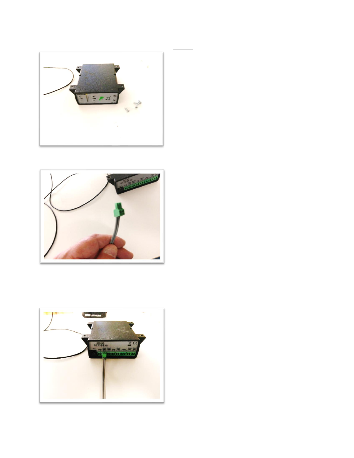
A31 Amplifier
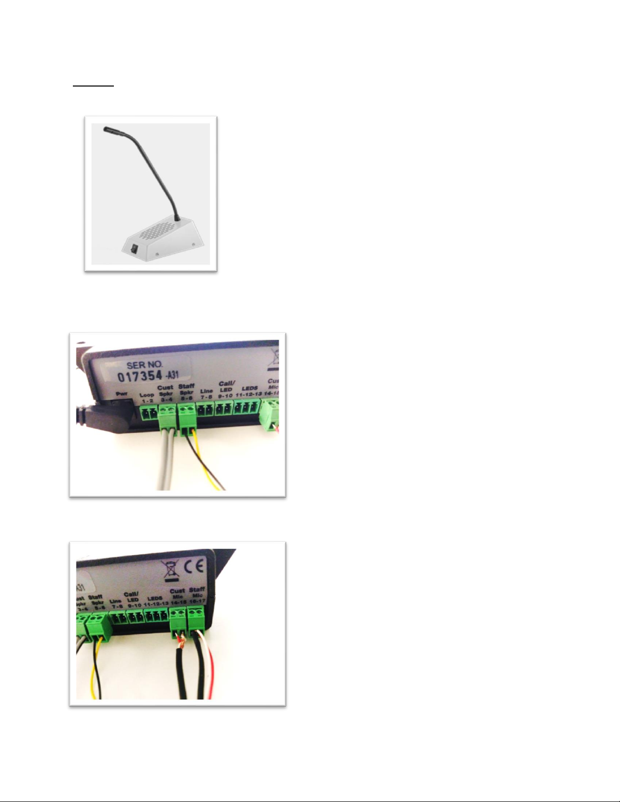
STS-C100 Microphone module and silicone gaskets
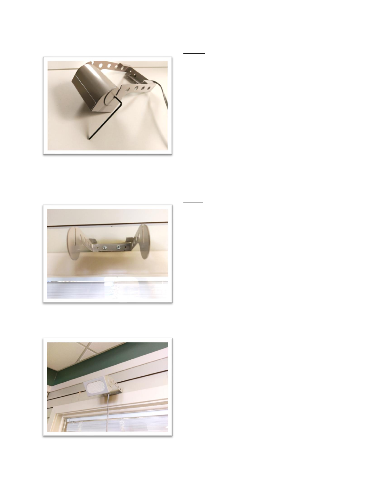
Customer overhead speaker
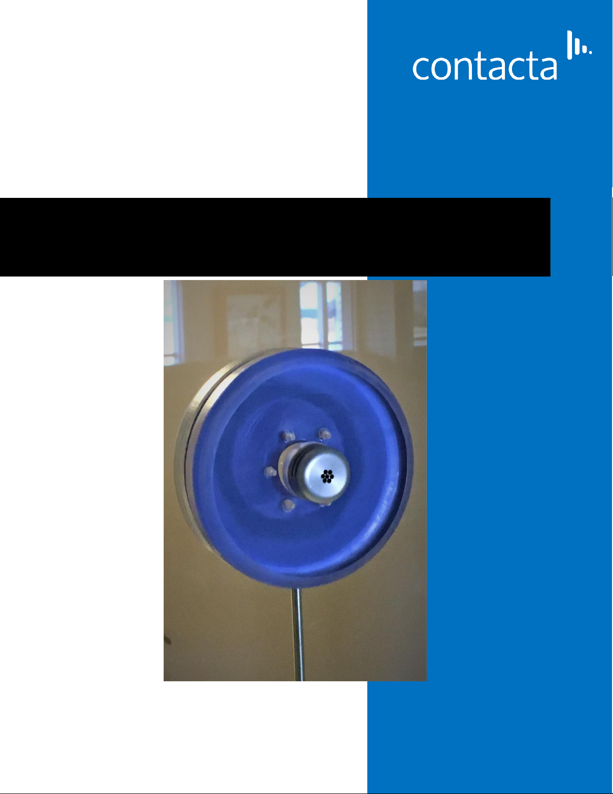
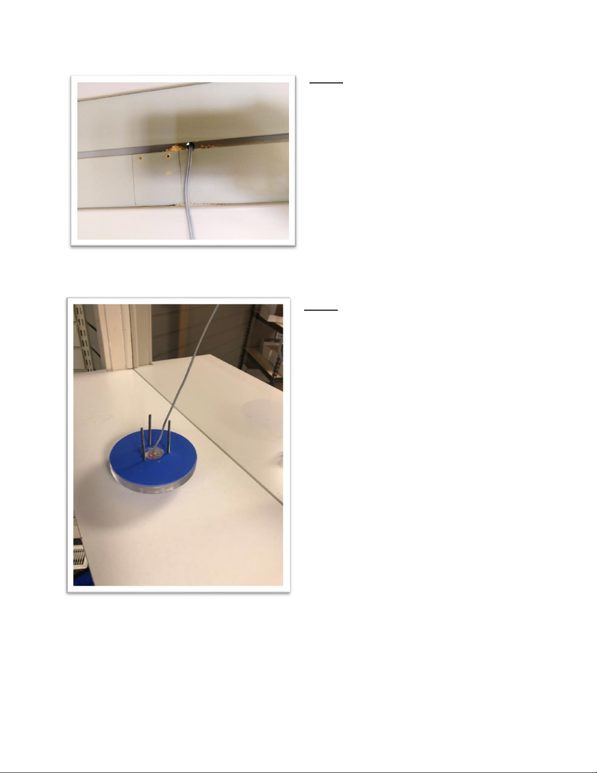
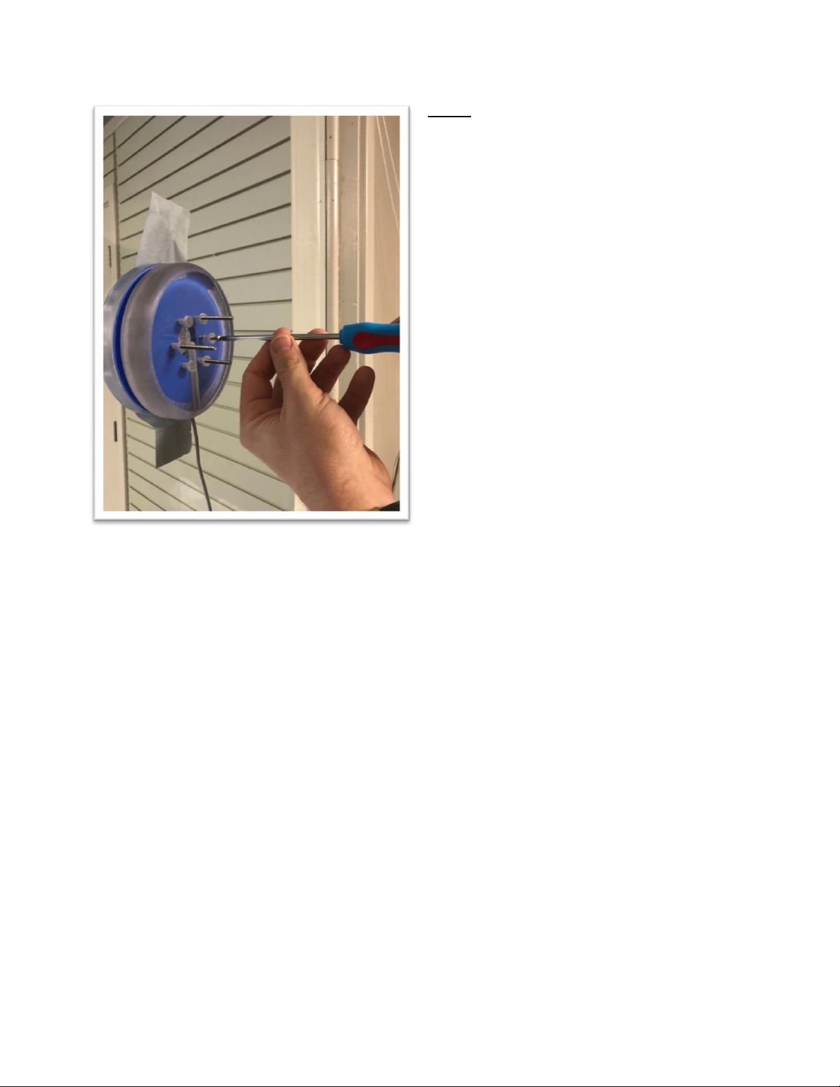
Staff combined speaker and microphone unit
Hearing Loop aerial window label
Power Supply
Steel tubing (for wiring)
(2) 8-32 mounting studs, (6) scored 8-32 mounting screws, wire clips, hearing
loop sticker (mounting screws for outside speaker)
Required tools –Drill with 3/16 bit, Small screwdriver. #2 Philips screwdriver. ¼”
tube bender and cutter