Contec ECH-PCI-CE-H2B User manual

PC-HELPER
PCI Bus Expansion Chassis
Short size, 2-Slots, BLACK
ECH-PCI-CE-H2B
Long size, 2-Slots, BLACK
ECH-PCI-CE-F2B
Short size, 4-Slots, BLACK
ECH-PCI-CE-H4B
Short size, 4-Slots, BLACK
ECH-PCI-CE-F4B
User’s Manual
CONTEC CO.,LTD.

ECH-PCI-CE-H2B, ECH-PCI-CE-F2B, ECH-PCI-CE-H4B, ECH-PCI-CE-F4B i
Check Your Package
Thank you for purchasing the CONTEC product.
The product consists of the items listed below.
Check, with the following list, that your package is complete. If you discover damaged or missing
items, contact your retailer
Product Configuration List
- Expansion chassis(Either the following)…1
[ECH-PCI-CE-H2B, ECH-PCI-CE-F2B
ECH-PCI-CE-H4B, ECH-PCI-CE-F4B]
- Board fixed screw …2
- AC adapter …1
- Power cable …1
- This User’s Manual (this booklet) …1
- Slot cover(Either the following)
ECH-PCI-CE-H2B…2, ECH-PCI-CE-F2B…2
ECH-PCI-CE-H4B…4, ECH-PCI-CE-F4B…4
POWER
Board fixed screw
Expansion chassis
User’s Manual
User’s Manual
Power cable Slot cover
AC adapter

ii ECH-PCI-CE-H2B, ECH-PCI-CE-F2B, ECH-PCI-CE-H4B, ECH-PCI-CE-F4B
Copyright
Copyright 2007 CONTEC CO., LTD. ALL RIGHTS RESERVED.
No part of this document may be copied or reproduced in any form by any means without prior written
consent of CONTEC CO., LTD.
CONTEC CO., LTD. makes no commitment to update or keep current the information contained in
this document. The information in this document is subject to change without notice.
All relevant issues have been considered in the preparation of this document. Should you notice an
omission or any questionable item in this document, please feel free to notify CONTEC CO., LTD.
Regardless of the foregoing statement, CONTEC assumes no responsibility for any errors that may
appear in this document or for results obtained by the user as a result of using this product.
Trademarks
MS, Microsoft, Windows and Windows NT are trademarks of Microsoft Corporation. Other brand and
product names are trademarks of their respective holder.

ECH-PCI-CE-H2B, ECH-PCI-CE-F2B, ECH-PCI-CE-H4B, ECH-PCI-CE-F4B iii
Table of Contents
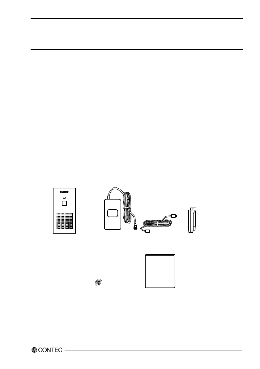
Check Your Package................................................................................................................................i
Copyright.................................................................................................................................................ii
Trademarks..............................................................................................................................................ii
Table of Contents ...................................................................................................................................iii
1BEFORE USING THE PRODUCT 1
About the Chassis....................................................................................................................................1
Features.............................................................................................................................................1
Expansion adapter (Option).............................................................................................................2
Combinations of Expansion Adapters and Expansion Chassis......................................................2
Restrictions.......................................................................................................................................3
Customer Support....................................................................................................................................4
Web Site ...........................................................................................................................................4
Limited One-Year Warranty...................................................................................................................4
How to Obtain Service............................................................................................................................4
Liability ...................................................................................................................................................4
Safety Precautions...................................................................................................................................5
Safety Information ...........................................................................................................................5
Handling Precautions.......................................................................................................................5
Environment.....................................................................................................................................7
Inspection .........................................................................................................................................7
Storage..............................................................................................................................................7
Disposal............................................................................................................................................7
2SETUP 9
What is Setup?.........................................................................................................................................9
Step 1 Preparation .................................................................................................................................10
Items to be prepared.......................................................................................................................10
Names of major parts.....................................................................................................................11
Step 2 Installing the Expansion Board .................................................................................................13
Step 3 Connecting the Cable.................................................................................................................14
Connecting the connection cable to the Expansion Adapter........................................................14
Connecting the connection cable to this product..........................................................................14
Connecting the AC Adapter...........................................................................................................15
Plugging the Power Cable .............................................................................................................15
Step 4 Installing the expansion adapter board .....................................................................................16
Step 5 Setup and Check ........................................................................................................................16
Starting the system.........................................................................................................................16
Setting up the hardware in Windows ............................................................................................17

iv ECH-PCI-CE-H2B, ECH-PCI-CE-F2B, ECH-PCI-CE-H4B, ECH-PCI-CE-F4B
Checking the hardware in Windows..............................................................................................17
Setup Troubleshooting...........................................................................................................................18
Symptoms and Actions...................................................................................................................18
3ABOUT HARDWARE 19
Hardware specification..........................................................................................................................19

1. Before Using the Product
ECH-PCI-CE-H2B, ECH-PCI-CE-F2B, ECH-PCI-CE-H4B, ECH-PCI-CE-F4B 1
1Before Using the Product
This chapter provides information you should know before using the product.
About the Chassis
This product is an expansion chassis that adds PCI bus slots to a PC. It can add PCI bus slots by
connecting an optional expansion adapter (EAD-CE-LPE, EAD-CE-EC). The board that can be
mounted is different depending on the model, ECH-PCI-CE-H2B, ECH-PCI-CE-H4B are short-type
[176.5 (L) x 107 (H) mm] PCI boards and ECH-PCI-CE-F2B, ECH-PCI-CE-F4B are long-type [313.8
(L) x 107 (H) mm] PCI boards. You can link the ON/OFF control of the chassis to that of your PC.
As the cabinet contains a built-in cooling fan, achieving a compact design, you can build a system even
in a limited space next to your PC. The product is also bundled with an easy-to-carry AC adapter.
Features
- PCI bus (5V/32bit 33MHz) slots can be added to your PC.
Two PCI bus (5V/32bit 33MHz) slots can be added.
ECH-PCI-CE-H2B, ECH-PCI-CE-F2B adds two PCI bus slots.
ECH-PCI-CE-H2B, ECH-PCI-CE-F4B adds four PCI bus slots.
This expansion chassis is connected to a PC using an optional expansion adapter.
- Short-type PCI bus boards can be connected. (ECH-PCI-CE-H2B, ECH-PCI-CE-H4B)
You can connect two short-type [176.5 (L) x 107 (H) mm] PCI boards.
ECH-PCI-CE-H2B can be connected two PCI Boards.
ECH-PCI-CE-H4B can be connected four PCI Boards.
- Long-type PCI bus boards can be connected. (ECH-PCI-CE-F2B, ECH-PCI-CE-F4B)
You can connect short-type [176.5 (L) x 107 (H) mm] and long-type [313.8(L) x 107 (H) mm] PCI
boards.
ECH-PCI-CE-F2B can be connected two PCI Boards.
ECH-PCI-CE-F4B can be connected four PCI Boards.
- ON/OFF control of the chassis can be linked to that of your PC.
You can link the ON/OFF control of the expansion chassis to that of your PC.
- The compact design of the cabinet with a built-in cooling fan enables space-saving system
construction.
As the cabinet contains a built-in cooling fan, achieving a compact design, you can build a system even
in a limited space next to your PC. The product is also bundled with an easy-to-carry AC adapter.

1. Before Using the Product
2ECH-PCI-CE-H2B, ECH-PCI-CE-F2B, ECH-PCI-CE-H4B, ECH-PCI-CE-F4B
Expansion adapter (Option)
Expansion Adapter for Express Card Slot : EAD-CE-EC
Expansion Adapter for PCI Express Slot : EAD-CE-LPE
Check the CONTEC’s Web site for more information on these expansion adapters.
Combinations of Expansion Adapters and Expansion Chassis
The expansion adapters and expansion chassis can be used in the following combinations:
Expansion chassis ECH-PCI-CE
Expansion
adapter -H2B -F2B -H4B -F4B -H4A -H7A -H13A
EAD-CE-EC ○○○○○× ×
EAD-CE-LPE ○○○○○○○
Expansion Chassis
ECH-PCI-CE-H2B ECH-PCI-CE-F2B ECH-PCI-CE-H4B ECH-PCI-CE-F4B
ECH-PCI-CE-H4A ECH-PCI-CE-H7A ECH-PCI-CE-H13A
Expansion Adapter
EAD-CE-EC EAD-CE-LPE

1. Before Using the Product
ECH-PCI-CE-H2B, ECH-PCI-CE-F2B, ECH-PCI-CE-H4B, ECH-PCI-CE-F4B 3
Restrictions
This product is used in a combination with the optional expansion adapter. The following restrictions
apply to the situation when the expansion adapter is connected to the expansion chassis.
This product has restrictions on the types of PCs and boards that can be used.
Be sure to check the following restrictions before use.
< Restrictions of PC>
This product uses the PCI-to-PCI Bridge to extend the bus.
The PCI boards plugged in PCI slots in this product are recognized if the PCI-to-PCI bridge is
recognized by the BIOS in the PC used. Ask the PC vendor for whether the BIOS recognizes the
PCI-to-PCI bridge.
< Restrictions on transfer rate >
When the expansion chassis accommodates a board that performs high-speed transfer such as bus
mastering, the overall transfer rate may be lower than that of PCI bus slots in the main unit of a desktop
PC.
This is caused by bus extension by the PCI-to-PCI Bridge.
The transfer rate may vary with the system configuration and the type of the PC.
< Restrictions of PCI board>
None of the following boards can be plugged into any expansion slot in this product.
- Video display board (VGA board)
- Board to connect a PCI bus expansion chassis
- Board explicitly stated not to be used with the PCI-to-PCI Bridge
- Some boards, even PCI-compliant ones, may not work depending on their specifications

1. Before Using the Product
4ECH-PCI-CE-H2B, ECH-PCI-CE-F2B, ECH-PCI-CE-H4B, ECH-PCI-CE-F4B
Customer Support
CONTEC provides the following support services for you to use CONTEC products more efficiently
and comfortably.
Web Site
Japanese http://www.contec.co.jp/
English http://www.contec.com/
Chinese http://www.contec.com.cn/
Latest product information
CONTEC provides up-to-date information on products.
CONTEC also provides product manuals and various technical documents in the PDF.
Free download
You can download updated driver software and differential files as well as sample programs available in
several languages.
Note! For product information
Contact your retailer if you have any technical question about a CONTEC product or need its price,
delivery time, or estimate information.
Limited One-Year Warranty
CONTEC products are warranted by CONTEC CO., LTD. to be free from defects in material and
workmanship for up to one year from the date of purchase by the original purchaser.
Repair will be free of charge only when this device is returned freight prepaid with a copy of the
original invoice and a Return Merchandise Authorization to the distributor or the CONTEC group office,
from which it was purchased.
This warranty is not applicable for scratches or normal wear, but only for the electronic circuitry and
original products. The warranty is not applicable if the device has been tampered with or damaged
through abuse, mistreatment, neglect, or unreasonable use, or if the original invoice is not included, in
which case repairs will be considered beyond the warranty policy.
How to Obtain Service
For replacement or repair, return the device freight prepaid, with a copy of the original invoice. Please
obtain a Return Merchandise Authorization number (RMA) from the CONTEC group office where you
purchased before returning any product.
* No product will be accepted by CONTEC group without the RMA number.
Liability
The obligation of the warrantor is solely to repair or replace the product. In no event will the
warrantor be liable for any incidental or consequential damages due to such defect or consequences that
arise from Safety Precautions.
Understand the following definitions and precautions to use the product safely.

1. Before Using the Product
ECH-PCI-CE-H2B, ECH-PCI-CE-F2B, ECH-PCI-CE-H4B, ECH-PCI-CE-F4B 5
Safety Precautions
Understand the following definitions and precautions to use the product safely.
Safety Information
This document provides safety information using the following symbols to prevent accidents resulting
in injury or death and the destruction of equipment and resources. Understand the meanings of these
labels to operate the equipment safely.
DANGER DANGER indicates an imminently hazardous situation which, if not avoided, will
result in death or serious injury.
WARNING WARNING indicates a potentially hazardous situation which, if not avoided, could
result in death or serious injury.
CAUTION CAUTION indicates a potentially hazardous situation which, if not avoided, may
result in minor or moderate injury or in property damage.
Handling Precautions
DANGER
Do not use the product where it is exposed to flammable or corrosive gas. Doing so may result in
an explosion, fire, electric shock, or failure.
CAUTION
- Do not plug or unplug any board into or from an expansion slot with the PC or
this product powered.
Doing so may result in a malfunction, overheating, or fault.
Be sure to turn off the PC or this product and unplug their power cables before plugging or
unplugging any expansion board.
- Do not plug or unplug the cable interconnecting the PC and the expansion chassis with the PC or
this product powered.
- Do not turn on or off the power switch of this product with the PC powered. Doing so may result
in a malfunction.
- The total current consumption by the boards installed in the expansion slots in this product must not
exceed the maximum power capacity of its power supply.
Failure to supply ample power to expansion boards could result in a malfunction, overheating, or
fault.
- The ECH-PCI-CE-H2B must always be used standing vertically.
Doing so may result in a malfunction, overheating, or fault.
- The external supply voltage or drive current must not exceed the rating.
- Do not connect any signal other than specified to the on-board connector.
Doing so may result in a malfunction, overheating, fault, or damage.

1. Before Using the Product
6ECH-PCI-CE-H2B, ECH-PCI-CE-F2B, ECH-PCI-CE-H4B, ECH-PCI-CE-F4B
- If a specific expansion slot is recommended for a board, plug the board into that slot. Failure to do
so may result in a malfunction, overheating, fault, or damage.
- When plugging or unplugging the power cable, be sure to hold it by the plug itself.
- Since the expansion chassis is a precision device, do not store or use it where it is subject to shock
or vibration. Also avoid any place where the chassis is exposed to direct sunlight, extremely high
humidity, or much dust.
- Do not use or store the chassis where it is exposed to any chemical either directly or as vapor in the
air.
- The chassis has ventilating slits to prevent it from overheating. Avoid using the chassis with the
ventilating slits blocked or in an ill-ventilated place.
- Do not use the chassis near equipment generating a strong magnetic field or noise.
Doing so may result in a malfunction, overheating, fault, or damage in the chassis, your PC, or
both.
- It is very dangerous to use the chassis with water, liquid, or metal (conductive) chips left inside.
Be careful not to let such foreign matters in the chassis.
- The specifications of this product are subject to change without notice for enhancement or quality
improvement.
Even when using the product continuously, be sure to read the manual and understand the contents.
- Do not modify this product.
CONTEC will bear no responsibility for any problems, etc., resulting from modifying the product.
- Regardless of the foregoing statements, CONTEC is not liable for any damages whatsoever
(including damages for loss of business profits) arising out of the use of or inability to use this
CONTEC product or the information contained herein.
FCC WARNING
Changes or modifications not expressly approved by the party responsible for compliance could void the
user's authority to operate the equipment.

1. Before Using the Product
ECH-PCI-CE-H2B, ECH-PCI-CE-F2B, ECH-PCI-CE-H4B, ECH-PCI-CE-F4B 7
Environment
Use this product in the following environment. If used in an unauthorized environment, the chassis
may overheat, malfunction, or cause a failure.
Operating temperature
0 - 50°C
Humidity
20 - 80%RH (No condensation)
Corrosive gases
None
Floating dust particles
Not to be excessive
Inspection
Inspect the product periodically as follows to use it safely.
- Ventilating slits must neither be blocked nor have
dust or foreign matters adhering.
POWER
Storage
When storing this product, keep it in its original packing form.
(1) Wrap it in the packing material, then put it in the box.
(2) Store the package at room temperature at a place free from direct sunlight, moisture, shock,
vibration, magnetism, and static electricity.
Disposal
When disposing of the product, follow the disposal procedures stipulated under the relevant laws and
municipal ordinances.

1. Before Using the Product
8ECH-PCI-CE-H2B, ECH-PCI-CE-F2B, ECH-PCI-CE-H4B, ECH-PCI-CE-F4B

2. Setup
ECH-PCI-CE-H2B, ECH-PCI-CE-F2B, ECH-PCI-CE-H4B, ECH-PCI-CE-F4B 9
2Setup
This chapter explains how to set up the chassis.
Refer to the user’s manual for the expansion adapter EAD-CE-LPE, EAD-CE-EC as required.
What is Setup?
Setup means a series of steps to take before the product can be used.
Taking the following steps in this chapter sets up the ECH-PCI-CE-H2B.
Step 1 Preparation
Step 2 Installing the Expansion Board
Step 3 Connecting the Cable
Step 4 Installing the expansion adapter board
Step 5 Setup and Check
If setup fails to be performed correctly, refer to “Setup Troubleshooting”.

2. Setup
10 ECH-PCI-CE-H2B, ECH-PCI-CE-F2B, ECH-PCI-CE-H4B, ECH-PCI-CE-F4B
Step 1 Preparation
Configuration image
The photo is of the EAD-CE-EC+ECH-PCI-CE-H2B.
Figure 2.1. Configuration image
Items to be prepared
- PC
- Expansion adapter
Expansion adapter card…(a),
Connection Cable …(b)
- Expansion chassis
This product(Chassis)…(c) [Picture is ECH(PCI)-PCI-CE-H2B.]
AC adapter, Power cable (Bundled)
- PCI board to be installed
(c) (a)
(b)

2. Setup
ECH-PCI-CE-H2B, ECH-PCI-CE-F2B, ECH-PCI-CE-H4B, ECH-PCI-CE-F4B 11
Names of major parts
ECH-PCI-CE-H2B/F2B
Front view Back view
Figure 2.2. Names of major parts < ECH-PCI-CE-H2B/F2B >
Setting Jumper
The board mounted on the expansion chassis has a jumper. The jumper can be set to link the power
systems.
1 : Linked to the power of the PC
When the PC is turned on, the power of the expansion chassis also comes on.
2 : Linked to the power of the expansion chassis
When the power receptacle inside the expansion chassis is connected, the
power of the chassis comes on.
JP1
123
3 : Not linked
When the power switch at the front of the expansion chassis is turned on, the
power of the chassis comes on.
Figure 2.3. Setting Jumper
Slot Cover
Connection cable
Connecting
AC adapter
Connecting
Removed cover
screw
Power LED
Power Switch

2. Setup
12 ECH-PCI-CE-H2B, ECH-PCI-CE-F2B, ECH-PCI-CE-H4B, ECH-PCI-CE-F4B
ECH-PCI-CE-H4B/F4B
Front view Back view
Figure 2.4. Names of major parts < ECH-PCI-CE-H4B/F4B >
Setting Jumper
The board mounted on the expansion chassis has a jumper. The jumper can be set to link the power
systems.
1 : Linked to the power of the PC
When the PC is turned on, the power of the expansion chassis also comes on.
2 : Linked to the power of the expansion chassis
When the power receptacle inside the expansion chassis is connected, the
power of the chassis comes on.
JP1
123
3 : Not linked
When the power switch at the front of the expansion chassis is turned on, the
power of the chassis comes on.
Figure 2.5. Setting Jumper
Slot cover
Connection cable
Connecting
AC adapter
Connecting
Removed cover
screw
Power LED
Power Switch

2. Setup
ECH-PCI-CE-H2B, ECH-PCI-CE-F2B, ECH-PCI-CE-H4B, ECH-PCI-CE-F4B 13
Step 2 Installing the Expansion Board
CAUTION
Before installing an expansion board on this product, be sure to turn off your PC or this product and
unplug the power cables from wall outlets.
Follow the procedure below to install the expansion board on this product.
(1) Unplug the AC adapter and Connection Cable from this product.
(2) Remove one screw from the top of the rear panel, then remove the chassis cover by sliding it to the
rear side (in the order of arrows 1 and 2).
The photo is of the ECH-PCI-CE-H2B.
Figure 2.6. Installing the Expansion Board
(3) Plug the expansion board into a PCI slot and fasten the bracket with the attached screw. Apply
slot covers to unused slots and fasten them with screws.
(4) Put the chassis cover back in place and fasten it with the removed screws.
Cover
1
2

2. Setup
14 ECH-PCI-CE-H2B, ECH-PCI-CE-F2B, ECH-PCI-CE-H4B, ECH-PCI-CE-F4B
Step 3 Connecting the Cable
Connecting the connection cable to the Expansion Adapter
Refer to the user’s manual for the expansion adapter EAD-CE-LPE, EAD-CE-EC to connect its
connection cable to the expansion adapter.
Connecting the connection cable to this product
Connect the connector of the connection cable to the connector of this product.
The interface connector is the leftmost connector on the rear panel of the expansion chassis.
Picture is ECH-PCI-CE-H2B.
Figure 2.7. Connecting the connection cable to this product
CAUTION
Do not plug the connection cable into any other connector as doing so can cause a fault.

2. Setup
ECH-PCI-CE-H2B, ECH-PCI-CE-F2B, ECH-PCI-CE-H4B, ECH-PCI-CE-F4B 15
Connecting the AC Adapter
(1) Connect the AC adapter to this product and turn the AC adapter’s thumb screw to lock the AC
adapter cable.
The photo is of the ECH-PCI-CE-H2B.
Figure 2.8. Connecting the AC Adapter
(2) Plug the power cable into the AC adapter.
(3) Plug the power cable into a wall outlet.
CAUTION
Do not connect the AC adapter to this product after plugging the AC adapter power cable into the
wall outlet, or the expansion chassis may cause a fault.
Connect the AC adapter to this product first, then plug the power cable into the wall outlet.
Plugging the Power Cable
(1) Please confirm the led on the front panel of expansion chasises is turned off.
(2) Please pull the plug out of the wall power outlet.
(3) Please pull out the plug of power cable from AC adaptor.
(4) Please uncork and pull out the AC adaptor from ECH(PCI)BE-H2B/F2B/H4B/F4B.
CAUTION
Do not uncork and pull out the AC adaptor from chasis when power cable is still connecting to the
wall power outlet. This may cause product maulfunction. Please uncork and pull out the AC
adaptor from the chasis after unplugging power cable from the wall power outlet.
Thumb screw
This manual suits for next models
3
Table of contents
Other Contec Chassis manuals