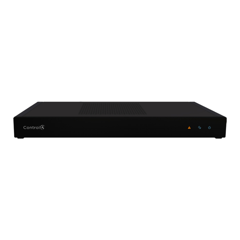
Contro l4 C4-IOX-E-B User manual

™Box Contents
• IOExtender
• PowerCord
• 6IREmitters
• 4PluggableContact/RelayConnectors
• 1URackMountEars
• WarrantyCard
Warnings
WARNING!Toreducetheriskofelectrical
shock,donotexposethisapparatustorainor
moisture.
AVERTISSEMENT!Pourréduirelerisquede
chocélectrique,n’exposezpascetappareilàla
pluieouàl’humidité.
WARNING!ThisCLASSIapparatusmust
beconnectedtoanACmainssocketoutlet
thathasaprotectiveearthingconnection
(i.e.,third-pronggroundconductor). DO
NOT DEFEAT THE PROTECTIVE EARTHING
CONNECTION!
Requirements and Specifications
Priortoinstallingthisproduct,ensurethat:Ethernet
networkwiringisininstalledandfunctioning.
TheIOExtenderspecicationsinclude:
Model Number C4-IOX-E-B
Network 10/100BaseTEthernet
Display LEDindicatorsfrontandback
Power Requirements 100-240VAC,50/60Hz,30W,
0.55A
Power Consumption Max:102BTUs/hour
Operating Temperature 32˚ - 104˚ F (0˚-40˚ C)
Storage Temperature -4˚ - 149˚ F (-20˚ - 65˚ C)
IR Out 5V,27mAmax/output
IR Capture 0-60KHz
Contacts DC-36Vmaximumoperation(low
voltage)
Theavailablecurrentfor12V
contactoutputsis1.25Amaximum,
sharedacrossalloutputs.
Relays AC-36V,2A
DC-24V,2A
Maximumoperation(lowvoltage)
Supported Model
• C4-IOX-E-BIOExtender
Introduction
TheControl4®IOExtenderopensupawholeworld
ofoptionsintheControl4systemtocontrolhome
theaters,videodevices,motionsensors,andother
devicesthatuseinfrared(IR),serial,contact,and
relayconnections.TheIOExtenderserveswellas
thecompaniontotheHomeControllerHC-1000
toexpandoutputcapability;inaddition,theIO
Extenderprovidesexibleoptionsformountinginan
equipmentrack(1U)oronawall.
Tomounttheunitonthewall,removetheoptional
feettousethekeyholesonthebottomoftheunit.
Thesekeyholesaredesignedtotthescrewspacing
foundonastandardU.S.double-gangbox.
Tomounttheunitinarack,installtheincluded
rackmountearsandinstallthedeviceintherack.
Thedevicecanbemountedwiththefrontfacing
outward,oroptionally,itcanbemountedonthe
equipmentrack’srearrailswiththerearofthedevice
facingoutwardforeasieraccesstotheinputand
outputconnectors.Therackmountearscanbe
mountedtothebottomofthedevicewiththeearsat
thefront(forfrontrackmounts),oralternatively,with
theearsattheback(forrearrackmounts).
IOExtender
InstallationGuide
1
™
Dimensions HxWxD:1.59”(40.4mm)x
16.84”(427.7mm)x6.44”(163.4
mm,includingconnectors)
Weight 4.8pounds/2.18kgs
Shipping Weight 6.8pounds/3.084kgs
Accessories Available for Purchase
• C4-CBLIR-BULK,IREmitters,5pack
• C4-CBLIRF-BULK,IREmitterswithoptical
feedback,5pack
Additional Resources
Thefollowingresourcesareavailabletoprovideyou
withadditionalsupport.
• YourControl4ResellerorControl4Dealer
• Control4Knowledgebase(kb.control4.com)
• ComposerdocumentationinonlinehelporPDF
formatavailableinthe‘SoftwareUpdates’page
(http://www.control4.com)
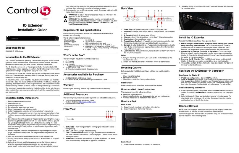
Front View
Figure1.FrontView
1 Status LED—Red,Orange,andBlueblinking
lightsindicatethestatusduringstartup.
2 Data LED—BlueLEDlightindicatesactivity.
3 Link/Identification LED—BlueLEDlightindicates
thattheIOExtenderhasbeenidentiedina
Control4Composerproject.Usethisbuttonalso
IOExtender
InstallationGuide
toidentifythedevice.
4 Power LED—BluelightindicatesACpoweris
present.Thedeviceturnsonimmediatelyafter
powerisappliedtothedevice.
Back View
Figure2.BackView
1 Power plug port—ACpowerreceptacleforanIEC
320powercord.
2 Serial Out—Four(4)serialoutputportsforDB9
(receivers,discchangers,etc.).
3 IR Output—Eight(8)IRoutputports,3.5mm.
4 Ethernet—One(1)RJ-45portfora10/100BaseT
Ethernetconnection.
5 Reset Button—RecessedResetbutton.
6 Relays (8 sets, Top Row)—Pluggableterminal
blockconnectorforeight(8)normallyclosedor
normallyopenedswitchableconnections.
7 Contacts (8 sets, Bottom Row)—Pluggable
terminalblockconnectorsforeight(8)dry
contactclosures,logicinputconnections,Door
ContactSensors,orMotionSensors.
8 LED Indicators—Status,Data,Link,Power.
Seetheprevioussection“FrontView”inthis
documentfordetails.
NOTES:
1 Foryourmountingconvenience,theLEDsonthe
frontandbackofthedevicearethesame.
2 AlwaysusetheIDbuttononthefrontofthe
deviceforidentication.
Mounting Options
BeforeyouinstalltheIOExtender,gureouthowyou
wanttoinstallit.
Youcan:
• Placeitonaatsurface
• Mountitonthewall
• Mountitonarack—frontfacingorbackfacing
2
24
3
1
5
4
36
7
8
21

networkconnectiontousealloutputportsas
designed.Whenconnected,theIOExtender
canaccessweb-basedmediadatabasesandthe
Controller.
2 Connect the IO Extender to the network:To
connectusinganEthernetconnection,plugthe
datacablefromthehomenetworkconnection
intotheIOExtenderRJ-45port(labeled
“Ethernet”).
3 Power up the IO Extender:PlugtheIOExtender
powercord(provided)intotheIOExtender
powerplugportandthentoanelectricaloutlet.
4 Connect the system devices:Followthesteps
describedinthe“ConnectDevices”sectionthat
follows.
Configure the IO Extender in Composer
Configure for Static IP
• Static IP address—Ifyouprefertosetupastatic
IPaddressforthisdevice,refertoAppendixA
“SettingUpaWiredandWirelessNetwork”(info
isavailableonlyuptoOS2.0)andthesection,
“SetUpNetworkConguration”intheComposer
Pro User GuideortheComposerProonlinehelp.
Add and Identify the Device
1 IntheComposerProSystemDesignview,select
theroominwhichthedeviceresides.Double-
clickIOExtenderintheItemspanetocopyitto
theprojecttree.
2 RefertoChapter5,“MakeandVerify
Connections”intheComposer Pro User Guide
(priortoOS2.0)orintheComposerProonline
helpfordetailsabouthowtoidentifythedevice.
Connect the Devices
NOTE:YoucanusetheComposersoftwareto
stepthroughtheconnectionprocessbeforeor
afterthephysicalconnectionsarecompleted.
ConnectallapplicabledevicestotheIOExtender
usingoneoftheconnectionoptionsdescribedinthe
followingtable.
Use Pluggable Terminal Block
Connectors
FortheContactandRelayports,theIOExtender
Flat Surface
Placethedeviceonaatsurface,andconnectthe
devices.
Mount on a Wall - New Construction
Thedevicecanmounttoa2-gangbackbox.
• Mountthe2-gangbackbox.
• Hangthedeviceonthetwo(2)screwsinthewall
boxfrontsideup.
• Connectthedevicesatthebottomofthedevice.
Mount in a Rack
FrontofRack
1 Screwtherackmountearstothefrontofthe
device.
2 Screwthedevicetothefrontoftherack.
Figure3.RackMount-Front
BackofRack
1 Screwtherackmountearstothebackofthe
device.
2 Screwthedevicetotherailsontherack.Ifyour
rackhasrearrails,thismaybeyourbestoption.
Figure4.RackMount-Back
Install the IO Extender
ToinstalltheIOExtender,followthesegeneralsteps:
1 Ensure that your home network is in place
before starting your system setup, including
your Controller:TheIOExtenderrequiresa
3

makesuseofPluggableTerminalBlockconnectors—
removableslotretentiontabstolockinindividual
wires.
ToconnectadevicetothePluggableTerminalBlock:
1 Insertone(1)ofthewiresrequiredforyour
deviceintotheappropriateopeninginthe
PluggableTerminalBlockyoureservedforthat
device(seeFigure5).
2 Insertthewireasfollows:
• Ifusingsolidcorewire,pushthewireintothe
holebelowtheslottedretentiontab,andensure
thatit’stightlysecured.
• Ifusingstrandedwire,pushtheslottedretention
tabinusingasmallat-bladescrewdriver.Insert
thewireintotheholebelowthetab,andthen
releasethetabtosecurethewire(seeFigure5).
Figure5.ConnecttoTerminalBlock
EXAMPLE:IfyouaddaMotionSensor,connectits
wirestothefollowingContactopenings—powerinput
to+12VoutputsignaltoSIG,andgroundconnector
toGND.See“ConnecttoaContactPort”or“Connect
totheRelayPorts”inthenextsectionstolearnhow
toconnectthedevices.
3 RepeatSteps1and2forallwiresrequiredfor
yourdevice.
NOTE:Ifyouconnectdrycontactclosure
devices,suchasdoorbells,connecttheswitch
between+12V(Power)andSIG(Signal).
Connect to a Contact Port
TheIOExtenderprovideseight(8)Contactports.
Seethefollowinggurestodeterminehowto
connectthedevicetoacontactport.
Figure6.ContactforVoltageSource(e.g.,Motion
Sensor)
NOTE:+12VandGNDareusedtopowerthe
MotionSensor.SIGandGNDareusedto
detectthestateoftheContactintheMotion
Sensor.
Figure7.ContactforDryContact(e.g.,DoorContact
Sensor)
Figure8.ContactforSelf-PoweredVoltageDevice
Connect to the Relay Ports
TheIOExtenderprovideseight(8)Relayports.
Formostapplications,attachone(1)wiretothe
commonterminal,andtheothertothenormallyopen
terminal.TheRelayswitchesclosewhentheRelayis
activated.TheIOExtendercansupportapplications
thatrequireanormallyclosedContact.
Figure9.RelayPort:NormallyOpen
4

©2012 Control4. All rights reserved. Control4, the Control4 logo, the Control4 iQ logo and the Control4 certified logo are registered trademarks or trademarks of Control4 Corporation in
the United States and/or other countries. All other names and brands may be claimed as the property of their respective owners.
control4.com|
™
Figure10.RelayPort:NormallyClosed
Connect to the Serial Ports
TheIOExtenderprovidesfour(4)DB9-styleserial
portsthatusetheRS-232protocol.Connectadevice
totheIOExtender—forexample,areceiverordisc
changer—byaligningthepins,insertingtheplugand
tighteningthescrews.Serialportssupportmany
dierentbaudrates.AllportssupportOdd,Evenand
NoParityandhardwareowcontrol.
Set Up IR Emitters
Yoursystemmaycontainthird-partyproductsthat
arecontrolledwithIRcommands.
TocontroladevicethatonlyrecognizesIR
commands,completethefollowingsetup:
IR Emitters
1 Plugthe3.5mmconnectorendofoneoftheIR
stick-onemittersprovidedintoanIROutporton
theIOExtender.
2 Placethestick-onIRemitterendovertheIR
receiverontheDVDorBlu-rayplayer,TV,or
othertargetdevicetodriveIRsignalsfromtheIO
Extendertothetarget.
Troubleshooting
Reset Button
1 ToresettheIOExtenderforsystemrecovery,
onthebackofthedeviceinserttheendofa
paperclipintothesmallhole(totherightofthe
Ethernetconnector).
2 Powercyclethedevicebypressingandholding
theResetbuttonforabout5-7secondsandthe
StatusLEDblinksorange.Thisactionstartsthe
recoveryprocess.
Identification Button
1 Toresettothenetworkdefaults,onthefrontof
thedevicepowercycletheIOExtenderandhold
theIdenticationbuttonuntiltheData,Link,and
PowerLEDsaresolidblue;immediatelyrelease
thebutton.
2 Ifduringthebootsequence,theStatusLEDstays
Orange,pressandholdtheIdenticationbutton
untiltheLEDblinksBlue,andthenreleaseit.
Regulatory/Safety Information
Toreviewregulatoryinformationforyourparticular
Control4products,seetheinformationlocatedon
theControl4websiteat:http://www.control4.com/
regulatory/.
Warranty
Gotohttp://www.control4.com/warrantyfordetails.
About This Document
Partnumber:200-00141,Rev.M08/17/2012
5
Table of contents
Other Contro l4 Extender manuals

Contro l4
Contro l4 CXM-RCR1-B User manual

Contro l4
Contro l4 C4-IOX-E-B User manual

Contro l4
Contro l4 IO Extender V2 C4-IOXV2 User manual

Contro l4
Contro l4 CXM-RCR1-B User manual

Contro l4
Contro l4 ZXT30 ZigBee Extender 3 User manual

Contro l4
Contro l4 ZigBee Extender 3 User manual

Contro l4
Contro l4 CXM-RCR1-B User manual