manuals.online logo
Brands
  1. Home
  2. •
  3. Brands
  4. •
  5. Contro l4
  6. •
  7. Power Supply
  8. •
  9. Contro l4 C4-BPS48 User manual

Contro l4 C4-BPS48 User manual

™
Warnings and Considerations
WARNING! The Bus Power Supply should be installed by a licensed
electrician in accordance with all national and local electrical codes.
ATTENTION! Le bus d’alimentation doit être installé par un électricien
certifié conformément à tous les codes électriques nationaux et locaux.
WARNING! Improper use or installation can cause SERIOUS INJURY,
DEATH or LOSS/DAMAGE OF PROPERTY.
ATTENTION! Une mauvaise utilisation ou installation peut entraîner des
blessures graves, décès ou perte / dommages à la propriété.
WARNING! This device must be protected by a circuit breaker (20A max).
ATTENTION! Cet appareil doit étre protègè par un disjoncteur (20A max.)
IMPORTANT! Use this device only with copper or copper-clad wire. Do
not use aluminum wiring. This product has not been approved for use with
aluminum wiring.
IMPORTANT! Using this product in a mannner other than outlined in this
document voids your warranty. Further, Control4 is NOT liable for any
damage incurred with the misuse of this product. See “Troubleshooting.”
IMPORTANT! This is an electronic device with intricate components.
Handle and install with care!
Front View
Figure 1. Front View
A Line Voltage Connector
B Low Voltage Connector
C Bendable Tab
D Mounting Bracket
Supported Model
đŏ C4-BPS48 Bus Power Supply, 48V
Introduction
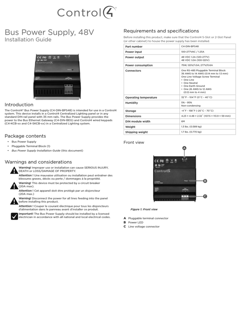
The Control4® Bus Power Supply, 48V is intended for use in a Control4 system and
installs in a Control4 Panelized Lighting panel. The Bus Power Supply provides the
power to the Bus Ethernet Gateway and Control4 Configurable Wired Keypads.
Box Contents
đŏ Bus Power Supply
đŏ Bus Power Supply Mounting Bracket
đŏ Warranty Card
đŏ One (1) Ferrite Clamp
đŏ Two (2) Mounting Screws
đŏ 1/ŏ+3!.ŏ1,,(5Čŏąĉŏ*/0((0%+*ŏ1% !ŏ(this document)
Specifications
Model Number C4-BPS48
Power Input 100-240VAC, 50/60Hz
Power Output 48VDC
Power Consumption 100-240VAC at 1.8A
48VDC at 1.8A (or 86.4W)
Connectors One (1) Line Voltage Screw
Terminal one (1) Line, one (1)
Neutral, one (1) Earth Ground
One (1) low-voltage screw
terminal; two (2) 0V, two (2) 48V
Environmental
Operational Temperature 32˚F to 104˚F (0˚C to 40˚C)
Humidity 5% - 95%
Non-condensing
Storage -4˚ F - 158˚ F
(-20˚ C - 70˚ C)
Dimensions and Weight
H x W x D 5.5” x 9.75” x 7.75” (139.7mm x
247.65mm x 196.85mm)
Weight 2.3 lbs. (1.04 kg)
Shipping Weight 2.85 lbs. (1.28 kg)
Bus Power
Supply, 48V
Installation Guide
B
A
D
C
Pre-Installation Instructions
Before You Install in a Control4 Panel
1 Use Composer Pro to add the Bus Power Supply to a project, define its
location in a panel, and print the panel report. See the +),+/!.ŏ.+ŏ/!.ŏ
1% ! for details.
2 Install the panel following the instructions in the Ćġ(+0ŏ* ŏĂġ(+0ŏ*!(ŏ
*/0((0%+*ŏ1% !.
3 Install and wire the Terminal Block for the Bus Power Supply following the
instructions in the !.)%*(ŏ(+'ŏ*/0((0%+*ŏ1% ! and in the location
defined by the Composer Pro panel reports.
Installation Instructions
Install in a Control4 Panel
1 The Mounting Bracket fits both 2-Slot and 5-Slot Panels. If you are mounting
into a 2-Slot Panel, gently bend the tab 90 degrees to the left or right (see
Figure 1).
IMPORTANT! To prevent sharp edges and cut fingers, use caution when
bending the tab and avoid breaking it.
2 Orient the Bus Power Supply bracket with the mounting holes facing down
(see Figure 2).
Figure 2. Bus Power Supply Mounting Bracket
A Mounting Bracket
B Terminal Screws
C Mounting Holes
D Bendable Tab
3 Insert the Bus Power Supply into the bracket with the screw terminals facing
toward you on the left-hand side (see Figure 2).
4 Rotate the bracket and Bus Power Supply 180 degrees, align the power
supply mounting holes, and attach the Bus Power Supply to the bracket using
the screws provided (see Figure 3).
Figure 3. Mounting Holes
5 Use a screwdriver to remove the screws and the Class 1/2 Swivel Divider plate
at the bottom of the panel (see Figure 4). You’ll be installing the Bus Power
Supply and bracket there.
Figure 4. Divider Plate
6 Mount the Bus Power Supply and bracket using the same screws that were
used to mount the divider plate (see Figure 5).
Mounting Holes
Divider
Plate
A
BC
C
D
™
Figure 5. Installed Bus Power Supply and Bracket
A Bus Ethernet Gateway
B Ferrite Clamp
C Bus Power Supply
D Mounting Bracket
Installing the Ferrite Clamp
1 Pick up the ferrite clamp and open it (you may need to use a small
screwdriver to open it).
2 Place the power cable in the clamp, and then thread the cable through the
clamp, around the clamp, and back through the clamp again (see Figure 6).
3 Close the clamp until it snaps shut.
Figure 6. Ferrite Clamp Installation
Wiring Diagram
Figure 7. Bus Power Supply Wiring Diagram
Troubleshooting
Symptom Possible Solution
Power supply does not
power on.
Make sure the module is connected securely to the
Mains power supply.
Additional Information
To view a video about how to install the Bus Power Supply, Bus Ethernet Gateway
and wired keypads, refer to *!(%6! ŏ%#$0%*#Čŏ.0ŏąčŏ%.%*#ŏ1/ŏ!2%!/ŏĒŏ
!5, / on the Control4 University or Panelized Lighting products page at www.
control4.com.
For complete bus wiring scenarios, see the !5, ŏ1/ŏ%.%*#ŏ1% ! at www.
control4.com.
Regulatory/Safety Compliance
To review regulatory information for your particular Control4 products, see
the information located on the Control4 website at: http://www.control4.com/
regulatory/.
Warranty
For complete warranty information, including details on consumer legal rights as
well as warranty exclusions, review the Warranty card or visit www.control4.com/
warranty.
About this Document
Part Number: 200-00362, Rev. A 8/01/2013 BN
A
CCC
CCD
B
Bus Ethernet Gateway
To Keypads Max 40
Keypads
Max 1000ft
GND D
_
D+ V+ GND D
_
D+ V+
Bus Power Supply
LNE0V0V48V48V
To Terminal Block
ENL
Copyright ©2013 Control4. All rights reserved. Control4, the Control4 logo, the Control4 iQ logo and the Control4 certified logo are registered trademarks or trademarks of Control4 Corporation in
the United States and/or other countries. All other names and brands may be claimed as the property of their respective owners Pricing and specifications are subject to change without notice

Other Contro l4 Power Supply manuals

Contro l4 C4-KPS48-BL User manual

Contro l4

Contro l4 C4-KPS48-BL User manual

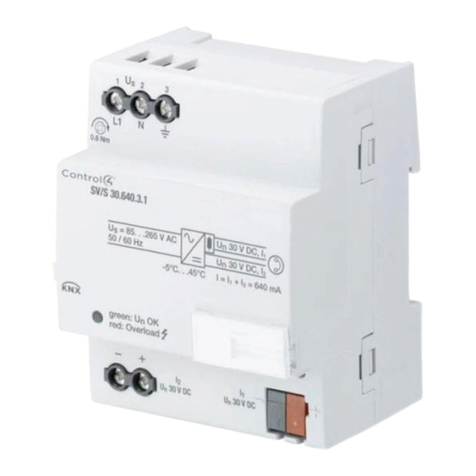
Contro l4 C4-DIN-BPS48 User manual

Contro l4

Contro l4 C4-DIN-BPS48 User manual

Contro l4 C4-KNX-PS640MA User manual

Contro l4

Contro l4 C4-KNX-PS640MA User manual

Popular Power Supply manuals by other brands

Thermaltake W0104 Toughpower 650 AP Supplement sheet

Thermaltake

Thermaltake W0104 Toughpower 650 AP Supplement sheet

Fike EPACO PSU E10-0067 Installation and operation instruction

Fike

Fike EPACO PSU E10-0067 Installation and operation instruction

EMC VI-200    ma Design guide & applications manual

EMC

EMC VI-200 ma Design guide & applications manual

Fracarro PSU3000 operating instructions

Fracarro

Fracarro PSU3000 operating instructions

gefran AFE200 4 Series instruction manual

gefran

gefran AFE200 4 Series instruction manual

Pulsar PSCC351400 quick start guide

Pulsar

Pulsar PSCC351400 quick start guide

Clore Automotive Truck PAC ES-6000 user manual

Clore Automotive

Clore Automotive Truck PAC ES-6000 user manual

ZALMAN ZM500-GLX user manual

ZALMAN

ZALMAN ZM500-GLX user manual

Motech DS3640 user manual

Motech

Motech DS3640 user manual

Siemens PSC-12 installation instructions

Siemens

Siemens PSC-12 installation instructions

D-Link RPS DPS-200 Quick installation guide

D-Link

D-Link RPS DPS-200 Quick installation guide

SamplexPower SEC-1223BBM-230 owner's manual

SamplexPower

SamplexPower SEC-1223BBM-230 owner's manual

Littfinski Daten Technik SNG-10 Operating	 instruction

Littfinski Daten Technik

Littfinski Daten Technik SNG-10 Operating instruction

HELVAR Digidim 401 manual

HELVAR

HELVAR Digidim 401 manual

National Instruments VirtualBench VB-8034 quick start

National Instruments

National Instruments VirtualBench VB-8034 quick start

awieco Power supply user manual

awieco

awieco Power supply user manual

Joy-it JT-RD6006-Case02 quick start guide

Joy-it

Joy-it JT-RD6006-Case02 quick start guide

Mitsubishi Electric PAC-SC51KUA installation manual

Mitsubishi Electric

Mitsubishi Electric PAC-SC51KUA installation manual

manuals.online logo
manuals.online logoBrands
  • About & Mission
  • Contact us
  • Privacy Policy
  • Terms and Conditions

Copyright 2025 Manuals.Online. All Rights Reserved.