manuals.online logo
Brands
  1. Home
  2. •
  3. Brands
  4. •
  5. Contro l4
  6. •
  7. Power Supply
  8. •
  9. Contro l4 C4-KNX-PS640MA User manual

Contro l4 C4-KNX-PS640MA User manual

Power Supply Standard, 640 mA, MDRC, C4-KNX-PS640MA (KNXPROD File Name: SV/S 30.640.3.41) 200-00549-B 10262018 LW
Contents
1
1.1 Using the product manual............................................................................................................ 5
1.1.1 Structure of the product manual .................................................................................................. 5
1.2 Product and functional overview.................................................................................................. 6
1.2.1 Brief overview.............................................................................................................................. 6
2
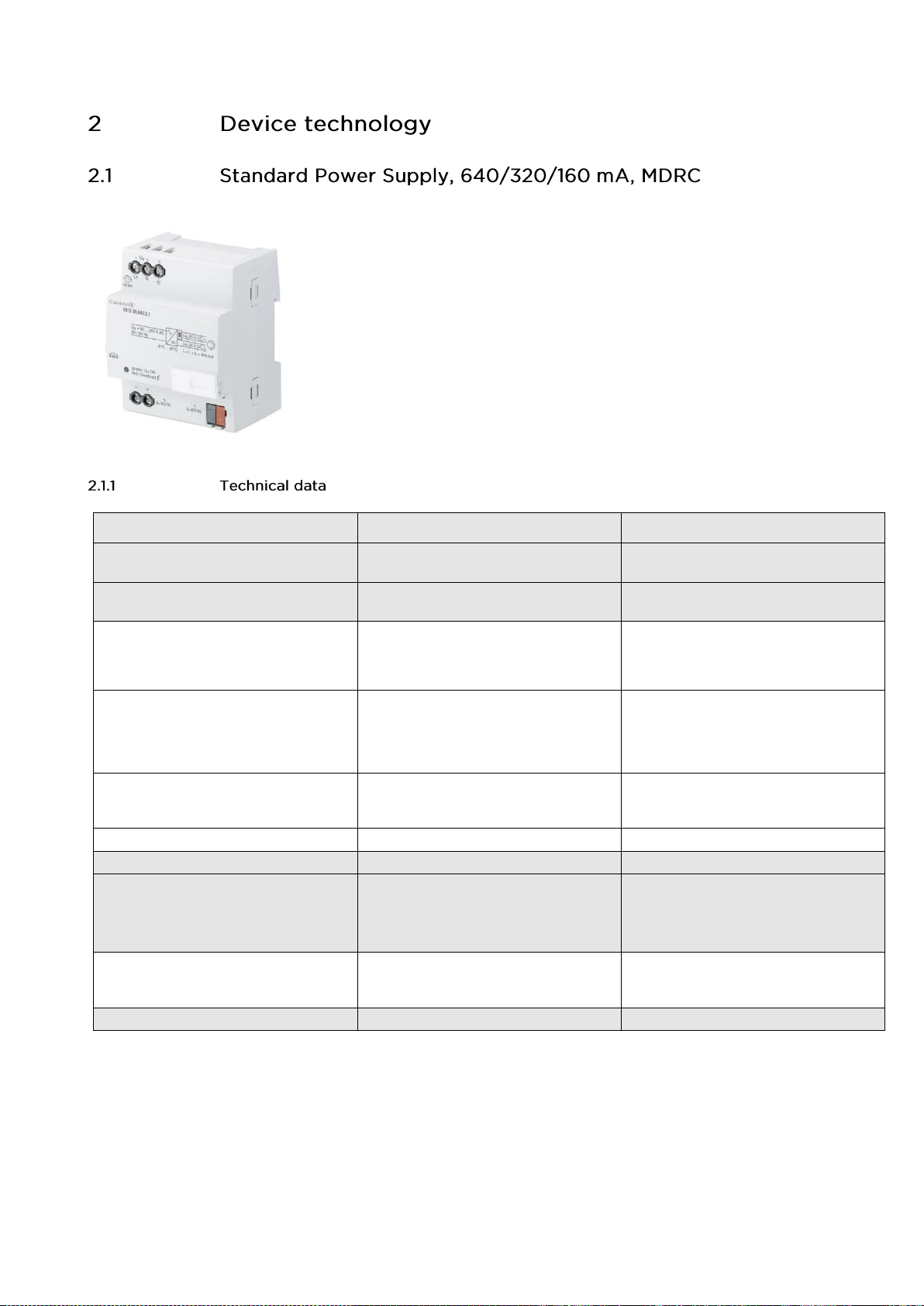
2.1 Standard Power Supply, 640/320/160 mA, MDRC...................................................................... 7
2.1.1 Technical data............................................................................................................................. 7
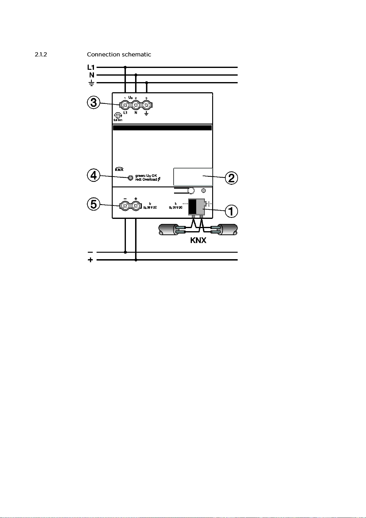
2.1.2 Connection schematic ................................................................................................................. 9
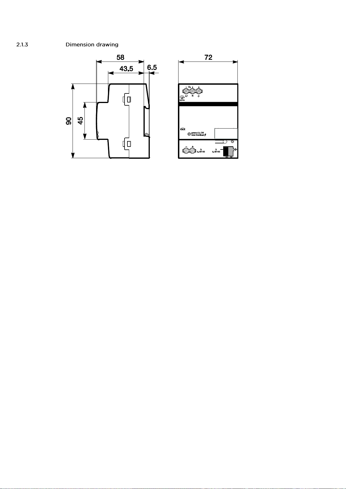
2.1.3 Dimension drawing.....................................................................................................................10
2.1.4 Operating and display elements.................................................................................................11
2.1.5 Mounting and installation............................................................................................................11
2.2 Conversion of previous application program versions ................................................................12
2.2.1 Procedure...................................................................................................................................12
3
3.1 Additional voltage output ............................................................................................................13
3.2 Reset..........................................................................................................................................14
3.3 Faults..........................................................................................................................................15
A
A.1 Ordering details..........................................................................................................................16
This manual describes the function and configuration of the Power Supply Standard, 640 mA, MDRC.
Use ETS v.5.6.6 (or higher).
Power Supply Standard, 640 mA, MDRC, SKU: C4-KNX-PS640MA.
KNXPROD filename: SV/S 30.640.3.41, download: https://ctrl4.co/knx-ps640ma
Subject to change.
Exclusion of liability:
Although the contents of this document have been checked to ensure that they are consistent with the
hardware and software, deviations cannot be completely excluded.
We therefore cannot accept liability. Any necessary corrections will be incorporated in new versions of
the manual.
Please inform us of any suggested improvements.
Control4®KNX
The Control4®KNX Power Supply Standard, 640 mA, MDRC, SKU: C4-KNX-PS640MA (KNXPROD File
Name: SV/S 30.640.3.41. Download: https://ctrl4.co/knx-ps640ma) provides the system voltage (SELV) for
KNX components. The choked output voltage powers individual components and enables them to
communicate.
This manual provides detailed technical information about the power supplies and how to mount and
program them. Device application is explained using examples.
This manual is subdivided into the following sections:
Section 1 General
Section 2 Device technology
Section 3 Commissioning
Section 4 Planning and application
Section A Appendix
All parameters are initially described in chapter 3. Following the parameter descriptions are descriptions
for the communication objects.
Notes and safety instructions are represented as follows in this manual:
Please note
Tips for usage and operation
Examples
Application examples, installation examples, programming examples
Important
These safety instructions are used as soon as there is danger of a malfunction without risk of damage
or injury.
Caution
These safety instructions are used as soon as there is danger of a malfunction without risk of damage
or injury.
Danger
These safety instructions are used if there is a danger to life and limb with inappropriate use.
Danger
These safety instructions are used if there is an extreme danger to life with inappropriate use.
Control4®KNX
Each Control4®KNX Power Supply Standard, 640 mA, MDRC, SKU: C4-KNX-PS640MA (KNXPROD File
Name: SV/S 30.640.3.41. Download: https://ctrl4.co/knx-ps640ma) has an integrated choke. It connects to
the KNX bus via a bus connection terminal.
Devices with diagnostics or bus functions for complex applications are available alongside standard
devices. An uninterruptable battery backed-up version is also available.
C4-KNX-PS640MA
KNXPROD File Name:
SV/S 30.640.3.41
Property
Standard
Supply voltage (in V AC)
100 –240
KNX rated voltage (in V DC)
30
KNX rated current (in mA)
640
Type of installation
MDRC
Mounting width in space units
4
Integrated choke
◼
Short-circuit and overload
monitoring
◼
Mains failure back-up time
(in ms)
200 ms
Mains failure back-up time
If used with a
sealed lead-acid battery, e.g.
- AM/S 12.1
- SAK 7
- 2 x SAK 7 in parallel
- SAK 12
- 2 x SAK 12 in parallel
- SAK 17:
- 2 x SAK 17 in parallel
-
Output voltage without
choke (30 V DC)
◼
Diagnostics or bus function
-
Output voltage indicator
◼
Overload Indicator
◼
Bus current indicator
-
Telegram traffic indicator
-
Communication error indicator
-
Bus reset button and indicator
-
Mains voltage OK indicator
-
Battery voltage OK indicator
-
Floating contact
for fault reporting
-
Control4®KNX
KNX power supplies generate and
monitor the KNX system voltage (SELV).
The bus line is decoupled from the power
supply by an integrated choke.
The voltage output is short-circuit and
overload protected.
The two-color LED indicates device
output status.
This device has an additional 30 V DC
short-circuit and overload protected
voltage output that can be used to
power an additional bus line (in
combination with a separate choke).
Supply
Supply voltage Us
100 –240 V AC, 50/60 Hz
(85…265 V AC)
Power consumption
Normal operation Maximum
24 W 55 W
Power loss
Normal operation Maximum
4 W 9 W
Outputs
KNX voltage output I1
Rated voltage UN
Minimum distance between 2 power supplies
in one line
1 line with integrated choke
30 V DC +1/-2 V, SELV
200 m (KNX bus line)
Voltage output I2
Rated voltage UN
without choke
30 V DC +1/-1 V, SELV
The voltage output without choke may only be
used to power an additional bus line in
combination with a separate choke.
Current
total current I1and I2
Rated curr. Overload curr. Short-circuit curr.
INIOvl ISc
640 mA 0.9 A 1.4 A
Power failure buffering time
200 ms
Connections
KNX
Bus connection terminal
Mains voltage input
Screw terminal
0.2…2.5 mm2fine-strand
0.2…4 mm2solid
Tightening torque
Maximum 0.6 Nm
Operating and display elements
LED status (two-colored green/red)
Green: I < IOvl
Red: overload.
Red, flashing: short-circuit
Degree of protection
IP 20
EN 60 529
Control4®KNX
Protection class
II
EN 61 140
Isolation category
Overvoltage category
Pollution degree
III under EN 60 664-1
2 under EN 60 664-1
Temperature range
Operation
Storage
Transport
-5 °C…+45 °C
-25…+55 °C
-25…+70 °C
Ambient conditions
Maximum air humidity
93 %, no condensation allowed
Design
Modular installation device (MDRC)
Modular installation device, Pro M
Main dimensions (H x W x D)
90 x 72 x 64.5 mm
Mounting width
4 x 18 mm modules
Mounting depth
64.5 mm
Mounting
On 35 mm mounting rail
EN 60 715
Mounting position
As required
Weight
Approx. 0.26 kg
Housing, color
Plastic housing, gray
Approvals
KNX under EN 50 090-1, -2
CE mark
In accordance with the EMC guideline and low
voltage guideline
Important
If the device overheats due to extended overload (> 100 °C in housing) it switches off automatically.
The LED is off. The device can be switched on again only after it has been disconnected from the mains
for 60 seconds and has cooled to operational temperature internally.
Eliminate the cause of the overload before switching back on.
When commissioning the device, ensure that the rated current is not continuously exceeded.
The voltage output without choke ( I2) is not electrically isolated from the KNX voltage output (I1). It may
only be used to power an additional bus line in combination with a separate choke. It may not,
for example, be used to power IP devices (see SELV guidelines).
Devices are designed for continuous operation. They are not approved for frequent switching on and off.
Control4®KNX
1 Bus connection terminal
2 Label carrier
3 Power supply connection Us
4 Status LED
5 Voltage output without choke, I2
2CDC072007F0013
Control4®KNX
2CDC072013F0013
Control4®KNX
Indicator
Description
Function
LED status
(green/red)
Two-colored indicator for displaying mains
voltage, overload and short-circuit.
Overload and short-circuit current values
apply to the total current, I = I1+ I2
Green: Device operating normally (I < IOvl)
Red: Overload (IOvl < I < ISc)
Red, flashing: Current limiting is active
Output voltage regulated downwards
(I = ISc)
OFF: Mains voltage absent
Accessibility to the device for the purpose of operation, testing, visual inspection, maintenance and repair
must be provided compliant to VDE 0100-520.
Mounting
Mounting and commissioning may only be carried out by electrical specialists. The appropriate standards,
directives, regulations and specifications should be observed when planning and setting up electrical
installations.
Protect the device from moisture, dirt and damage during transport, storage and operation.
Only operate the device within the specified technical data!
The device should only be operated in an enclosed housing (distribution board)!
Cleaning
If devices become dirty, they can be cleaned using a dry cloth. Should a dry cloth not remove the dirt, they
can be cleaned using a slightly moistened cloth and soap solution. Corrosive agents or solutions should
never be used.
Maintenance
The device is maintenance-free. No repairs should be carried out by unauthorized personnel if damage
occurs, e.g. during transport and/or storage. The warranty expires if the device is opened.
Control4®KNX
For Control4®KNX devices, it is possible to adopt the parameter settings and group addresses from earlier
versions of the application program from ETS v.5.6.6 (or higher).
•Import the current VD file into ETS and add a product to the project, using the current application
program.
•After you have parameterized a device, you can transfer the settings to a second device. For this
purpose, the devices must already be available in the ETS project.
•Right click on the product and select Conversion in the context menu for this purpose.
•Then follow the instructions in the dialog window.
•Finally, you must replace the physical address and delete the old device.
Control4®KNX
Control4® KNX Power Supply Standard, 640 mA, MDRC, SKU: C4-KNX-PS640MA (KNXPROD File
Name: SV/S 30.640.3.41. Download: https://ctrl4.co/knx-ps640ma) devices have a 30 V DC voltage output
without choke. This can be used in combination with an additional choke to power a main or area line. To
do this, the devices must be installed in accordance with the connection schematic below.
Please note
The voltage output without choke may not be used for other purposes (e.g. for connecting sensors to a
binary input) because in the event of an error on the voltage output (e.g. a short-circuit) the power
supply and therefore the whole KNX line connected to it will fail!
The voltage output without choke ( I2) is not electrically isolated from the KNX voltage output (I1). It may
only be used to power an additional bus line in combination with a separate choke. It may not, for
example, be used to power IP devices (see SELV guidelines).
Control4®KNX
During a reset the bus line is disconnected from the output voltage and shorted. This restarts devices
connected to this bus line. The red Reset LED lights up for the duration of the reset. The LED goes off
when the reset is complete. A reset takes around 20 seconds.
If the line is to be disconnected from the voltage for an extended period, pull off the bus connection
terminals from the KNX power supply.
Reset via bus connection terminal
Pull off the device's bus connection terminal for approx. 20 seconds.
Control4®KNX
C4-KNX-PS640MA (KNXPROD File Name: SV/S 30.640.3.41. Download: https://ctrl4.co/knx-ps640ma)
Indicators for normal operation, short-circuit and overload
green/
red
Description
Recommendation
ON
green
Device operating normally.
ON
red
Output overloaded.
Rectify overload or reduce number of bus
devices until there is no longer an overload
and only the green UNOK LED is lit.
Flashing
red
Current limiting active.
Reduce number of bus devices until only the
green UNOK LED is lit.
Communication error indicators
Description
Recommendation
ON
The LED comes ON for 1 second if there is a
transmission error or if a telegram fails or is
incomplete (e.g. “BUSY”, “NAK” (receipt not
correct)).
If the LED lights up frequently or flashes, check
the topology or connections. For a more
accurate diagnosis, use ETS Bus Monitor
logging.
Control4®KNX
A Appendix
A.1 Ordering details
Short description
Description
Weight 1 pcs [kg]
Pkg qty [pcs.]
C4-KNX-PS640MA
KNXPROD File Name:
SV/S 30.640.3.41
Download:
https://ctrl4.co/knx-
ps640ma
KNX Power Supply, 640 mA, MDRC
0.25
1
Control4®KNX
Notes
Control4®KNX

Other Contro l4 Power Supply manuals

Contro l4 C4-BPS48 User manual

Contro l4

Contro l4 C4-BPS48 User manual

Contro l4 C4-DIN-BPS48 User manual

Contro l4

Contro l4 C4-DIN-BPS48 User manual

Contro l4 C4-KPS48-BL User manual

Contro l4

Contro l4 C4-KPS48-BL User manual

Popular Power Supply manuals by other brands

ACDC Dynamics PBU-1000W-UPS user manual

ACDC Dynamics

ACDC Dynamics PBU-1000W-UPS user manual

Monster PowerNet 300 Instructions and warranty information

Monster

Monster PowerNet 300 Instructions and warranty information

Altronix ALTV129-DC installation instructions

Altronix

Altronix ALTV129-DC installation instructions

Keysight N5741A user guide

Keysight

Keysight N5741A user guide

Lindy 73824 user manual

Lindy

Lindy 73824 user manual

Bluetti AC200MAX user manual

Bluetti

Bluetti AC200MAX user manual

Premier1Supplies SolarStop 80 operating instructions

Premier1Supplies

Premier1Supplies SolarStop 80 operating instructions

turck PSU67-3P-1MP-2M5-24200-F quick start guide

turck

turck PSU67-3P-1MP-2M5-24200-F quick start guide

Linear Technology 1459B quick start guide

Linear Technology

Linear Technology 1459B quick start guide

LC-POWER LC1200P manual

LC-POWER

LC-POWER LC1200P manual

Graymark 808 user manual

Graymark

Graymark 808 user manual

urmet domus 1061 instruction manual

urmet domus

urmet domus 1061 instruction manual

UTILCELL 121 Installation and user manual

UTILCELL

UTILCELL 121 Installation and user manual

Altronix AL400X220 Series installation guide

Altronix

Altronix AL400X220 Series installation guide

Delta Electronics DPS-300PB-2 Specifications

Delta Electronics

Delta Electronics DPS-300PB-2 Specifications

GE RAK3152 installation instructions

GE

GE RAK3152 installation instructions

TYVA PowerCase E2 quick start guide

TYVA

TYVA PowerCase E2 quick start guide

Antronix WayPoint3 installation guide

Antronix

Antronix WayPoint3 installation guide

manuals.online logo
manuals.online logoBrands
  • About & Mission
  • Contact us
  • Privacy Policy
  • Terms and Conditions

Copyright 2025 Manuals.Online. All Rights Reserved.