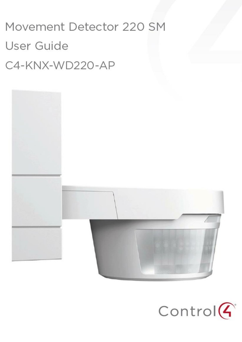
Contro l4 C4-KNX-BW180 Series User manual


Table of contents
200-00556-A 08222018-LW
Movement Detector 180 FM. SKU: C4-KNX-BW180-AS (KNXPROD File Name: SBW/U1.1.41-83)
Table of contents
2.1 Information and symbols used........................................................................................................................ 4
2.2 Intended use................................................................................................................................................... 5
2.3 Improper use .................................................................................................................................................. 5
2.4 Target group / Qualifications of personnel...................................................................................................... 6
2.5 Safety instructions .......................................................................................................................................... 7
3.1 Environment ................................................................................................................................................... 8
4.1 Scope of supply ............................................................................................................................................ 10
4.2 Overview of types ......................................................................................................................................... 10
4.3 Functions...................................................................................................................................................... 10
4.4 Device overview ........................................................................................................................................... 10
5.1 Dimensional drawings .................................................................................................................................. 11
5.2 Circuit diagrams............................................................................................................................................ 11
5.3 Detection range ............................................................................................................................................ 12
6.1 Mounting....................................................................................................................................................... 14
6.2 Electrical connection..................................................................................................................................... 15
7.1Hardware ...................................................................................................................................................... 16
7.2 Software ....................................................................................................................................................... 17
10.1 Cleaning ....................................................................................................................................................... 21
11.1 Application program...................................................................................................................................... 22
11.2 Overview of applications............................................................................................................................... 22
11.3 "Detector" application ................................................................................................................................... 23
11.4 "Brightness detection" application ................................................................................................................ 40
11.5 Communication objects —Movement Detector 180 FM Standard —Master.............................................. 43
11.6 Communication objects —Movement Detector 180 FM Standard —Slave................................................ 46
11.7 Communication objects —Movement Detector 180 FM Standard —Brightness detection ....................... 47
This manual describes the function and configuration of the Movement Detector 180 FM.
Movement Detector 180 FM, SKU C4-KNX-BW180-xx
(KNXPROD File Name: SBW/U1.1.41-83. Download: http://ctrl4.co/knx-bw180).
Subject to change.
Exclusion of liability:
Although the contents of this document have been checked to ensure that they are
consistent with the hardware and software, deviations cannot be completely excluded.
We therefore cannot accept liability. Any necessary corrections will be incorporated in new
versions of the manual.
Please inform us of any suggested improvements.

Notes on the instruction manual
3
Please read through this manual carefully and observe the information it contains. This will
assist you in preventing injuries and damage to property and ensure both reliable operation and
a long service life for the device.
Please keep this manual in a safe place.
If you transfer this device to another individual, please be sure they receive this manual.
Control4 accepts no liability for any failure to observe the instructions in this manual.
If you require additional information or have questions about the device, please contact Control4
or visit our web site at: www.control4.com.

Notes on the instruction manual
4
The device has been constructed according to the latest valid regulations governing technology
and is operationally reliable. It has been tested and left the factory in a technically safe and
reliable state.
However, residual hazards remain. Read and adhere to the safety instructions to prevent
hazards of this kind.
Control4 accepts no liability for any failure to observe the safety instructions.
The following Instructions point to particular hazards involved in the use of the device or provide
practical instructions.
Danger
Risk of death / serious damage to health
–The respective warning symbol in connection with the signal word "Danger"
indicates an imminently threatening danger which leads to death or serious
(irreversible) injuries.
Warning
Serious damage to health
–The respective warning symbol in connection with the signal word "Warning"
indicates a threatening danger which can lead to death or serious
(irreversible) injuries.
Caution
Damage to health
–The respective warning symbol in connection with the signal word "Caution"
indicates a danger which can lead to minor (irreversible) injuries.
Attention
Damage to property
–This symbol in connection with the signal word "Attention" indicates a
situation which could cause damage to the product itself or to objects in its
surroundings.
NOTE
This symbol in connection with the word "Note" indicates useful tips and
recommendations for the efficient handling of the product.
The following safety symbols are used in the operating manual.
This symbol alerts to electric voltage.

Notes on the instruction manual
5
This device is a movement detector for decentralized flush-mounted installation.
Depending on the setting, the movement detector responds to body heat and switches on the
lights.
The device is intended for the following:
■Operation according to the listed technical data
■Installation in dry interior rooms and suitable flush-mounted boxes
■Use with the connecting options available on the device
The intended use also includes adherence to all specifications in this manual.
Extensive functions are available for the movement detectors. The range of applications is
contained in chapter11 "Description of application / objects" (only in languages of the countries
DE, EN, ES, FR, IT and NL).
The integrated bus coupler makes possible the connection of a KNX bus line.
Each use not listed in see chapter “Intended use“ on page 5 is deemed improper use and can
lead to personal injury and damage to property.
Control4 is not liable for damages caused by use deemed contrary to the intended use of the
device. The associated risk is borne exclusively by the user/operator.
The device is not intended for the following:
■Unauthorized structural changes
■Repairs
■Outdoor use
■The use in bathroom areas
■Insert with an additional bus coupler

Notes on the instruction manual
6
Installation, commissioning and maintenance of the device must only be carried out by trained
and properly qualified electrical installers.
The electrical installer must have read and understood the manual and follow the instructions
provided.
The electrical installer must adhere to the valid national regulations in his/her country governing
the installation, functional test, repair and maintenance of electrical products.
The electrical installer must be familiar with and correctly apply the "five safety rules" (DIN VDE
0105, EN 50110):
1. Disconnect
2. Secure against being re-connected
3. Ensure there is no voltage
4. Connect to earth and short-circuit
5. Cover or barricade adjacent live parts
No special qualifications are needed to operate the device.

Notes on the instruction manual
7
Danger - Electric voltage!
Electric voltage! Risk of death and fire due to electric voltage of 230 V.
Dangerous currents flow through the body when coming into direct or indirect
contact with live components. This can result in electric shock, burns or even
death.
■Work on the 230 V supply system may only be performed by authorized and
qualified electricians.
■Disconnect the mains power supply before installation / disassembly.
■Never use the device with damaged connecting cables.
■Do not open covers firmly bolted to the housing of the device.
■Use the device only in a technically faultless state.
■Do not make changes to or perform repairs on the device, on its components
or its accessories.
■Keep the device away from water and wet surroundings.
Danger - Electric voltage!
Install the device only if you have the necessary electrical engineering
knowledge and experience.
■Incorrect installation endangers your life and that of the user of the electrical
system.
■Incorrect installation can cause serious damage to property, e.g. due to fire.
The minimum necessary expert knowledge and requirements for the installation
are as follows:
■Apply the "five safety rules" (DIN VDE 0105, EN 50110):
1. Disconnect
2. Secure against being re-connected
3. Ensure there is no voltage
4. Connect to earth and short-circuit
5. Cover or barricade adjacent live parts.
■Use suitable personal protective clothing.
■Use only suitable tools and measuring devices.
■Check the type of supply network (TN system, IT system, TT system) to
secure the following power supply conditions (classic connection to ground,
protective earthing, necessary additional measures, etc.).
Caution! - Risk of damaging the device due to external factors!
Moisture and contamination can damage the device.
■Protect the device against humidity, dirt and damage during transport,
storage and operation.

Notes on the instruction manual
8
Consider the protection of the environment!
Used electric and electronic devices must not be disposed of with domestic
waste.
–The device contains valuable raw materials which can be recycled.
Therefore, dispose of the device at the appropriate collecting depot.
All packaging materials and devices bear the markings and test seals for proper disposal.
Always dispose of the packaging material and electric devices and their components via the
authorized collecting depots and disposal companies.
The products meet the legal requirements, in particular the laws governing electronic and
electrical devices and the REACH ordinance.
(EU Directive 2002/96/EC WEEE and 2002/95/EC RoHS)
(EU REACH ordinance and law for the implementation of the ordinance (EC) No.1907/2006).

Notes on the instruction manual
9
Fig. 1: Product overview
[1] Support ring
[2] Cover frame (not included in scope of delivery)
[3] Flush-mounted insert (with integrated cover)
The movement detector (passive infrared detector) responds as soon as heat is registered in
the detection range and triggers a switching process. It can send switch-control telegrams to
KNX actuators. To switch on the lighting, for example. If the heat source leaves the detection
range or remains motionless, the lighting is switched off after an adjustable switch-off delay.
In addition to the detection of movement, the sensor can with the aid of its integrated message
function detect movements within a specific time with only a minimum of sensitivity. This allows
the sensor to be integrated in message systems.
The movement detector has a twilight sensing function. This function triggers the surveillance
function when the adjustable brightness values are exceeded or fall short (ambient brightness).
The parameters in the Engineering Tool Software (ETS) can be used to set the switch-off delay
and the brightness limit value of the installed twilight switch.
Use ETS 5.6 or higher.
The movement detector is anti-glare, i.e. when a light beam enters (e.g. with a flashlight), the
surveillance function is maintained for approximately 90 seconds.
The devices do not serve as a substitute for an alarm system.
The sensor is integrated in a flush-mounted insert [1].
The integrated bus coupler makes possible the connection to the KNX bus line.

Notes on the instruction manual
10
The scope of supply only contains the flush-mounted insert [1], including the pre-mounted
cover. It must still be completed with a suitable cover frame [2].
Article number
Product name
Sensor channels
C4-KNX-BW180-xx
Movement detector
1
Table 1: Overview of types
The following table provides an overview of the possible functions and applications of the
device:
Special features
Function
■4 channels
■Opening angle of 180°
■Freely programmable
■Protection type IP 20
■5 - 150 lux
■Switching
■Value transmitter
Table : Overview of functions
Fig. 2 Device overview of movement detector
[1] Programming LED
[2] Programming button
[3] Type plate
[4] Bus connection terminal

Notes on the instruction manual
11
Designation
Value
Power supply:
24 V DC (via bus line)
Bus subscribers
≤12 mA
Connection
Bus connection terminal: 0.4-0.8 mm
Line type:
J-Y(St)Y, 2x2x0.8 mm
Wire stripping:
6-7 mm
Opening angle
180°
Brightness limit value
1 - 500 lux
Mounting height
1.1 m - 1.3 m
Protection type
IP 20
Ambient temperature
-5°C - +45°C
Storage temperature
-20°C - +70°C
Table 2: Technical data
Fig. 3: Dimensions (all dimensions are in mm)
Bus
+-
+
-24 V DC

Notes on the instruction manual
12
Fig. 4: Electrical connection
Fig. 5: Detection range
[1] Mounting heights / Detection levels
[2] Detection range (0°C –+36°C);
[3] Horizontal reduction of the detection range by masking
6 m
3 m3 m
ca. 14˚
ca. 5˚
12 3
1,1 m -1,3m

Notes on the instruction manual
13
Danger - Electric voltage!
Install the device only if you have the necessary electrical engineering
knowledge and experience.
■Incorrect installation endangers your life and that of the users of the
electrical system.
■Incorrect installation can cause serious damage to property, e.g. due to fire.
The minimum necessary expert knowledge and requirements for the installation
are as follows:
■Apply the "five safety rules" (DIN VDE 0105, EN 50110):
1. Disconnect
2. Secure against being re-connected
3. Ensure there is no voltage
4. Connect to earth and short-circuit
5. Cover or barricade adjacent live parts.
■Use suitable personal protective clothing.
■Use only suitable tools and measuring devices.
■Check the type of supply network (TN system, IT system, TT system) to
secure the following power supply conditions (classic connection to ground,
protective earthing, necessary additional measures, etc.).
■Observe the correct polarity.

Notes on the instruction manual
14
NOTE
The devices with integrated bus coupler have been prepared for installing in
flush-mounted boxes in connection with the corresponding mounting plate.
Ensure that there is sufficient distance between movement detector and heat
sources such as lighting, heaters, etc., since these devices can cause incorrect
switching.
To install the device, perform the following steps:
1. Screw the support ring to the flush-
mounted box.
2. Attach the cover frame (not included
in scope of delivery).
3. Connect the bus line with the bus
connection terminal [1] (Chapter 6.2
“Electrical connection“ on page 15).
–Observe the correct polarity!

Notes on the instruction manual
15
4. Commission the device.
Programming is carried out via the
programming button [1].
[1] Programming button is on the
rear
[2] LED is on the front
5. Turn the device into the correct
installation position.
–The bus connection terminal [1]
must be at the rear at the bottom.
6. Snap the device into the support ring.
Carry out the electrical connection
according to the circuit diagram.
Fig. 6: Connection of bus coupler
KNX 24 V DC

Notes on the instruction manual
16
The movement detectors must be mounted to a solid wall, since each movement of the device
has the same effect as the movement of a heat source in the detection range.
–The optimum function of the movement detector is assured when it is mounted laterally to
the direction of movement (tangential approach).
–Since infrared waves cannot penetrate solid objects, ensure that nothing obstructs the "line
of vision" of the movement detector.
–A minimum distance of 2 m is to be kept from the direct light of lamps.
Mounting heights / Detection levels
■The movement detector has a selective lens which
has a detection level of approximately 3° upwards
and approximately 2° downwards.
Detection range
■The detection range is 180°, which is composed of
two 90° segments.
■The transmission range at a tangential / vertical
approach amounts to at least 6 m.
Narrowing the detection range
■The detection range can be narrowed via the
parameter setting within the Engineering Tool
Software (ETS) (Power-Tool)*
*Use ETS 5.6 or higher
ca. 14˚
ca. 5˚
1,1 m -1,3 m
6 m
3 m3 m

Notes on the instruction manual
17
To start the device a physical address must be assigned first. The physical address is assigned,
and the parameters are set with the Engineering Tool Software (ETS).
Use ETS 5.6 or higher.
NOTE
The devices are products of the KNX system and meet KNX guidelines. Detailed
expert knowledge by means of KNX training sessions for a better understanding
is assumed.
1. Connect a PC to the KNX bus line via the KNX interface.
–The Engineering Tool Software must be installed on the PC (ETS 5.6 or higher).
Download from: https://ctrl4.co/knx-bw180 (KNXPROD File Name: SBW/U1.1.41-83).
2. Switch on the bus voltage.
1. Press the programming button [1] on
the rear of the device.
–The red programming LED [2] on the
front of the device lights up.
2

Notes on the instruction manual
18
The group addresses are assigned in connection with the ETS.
The application program is available for download at https://ctrl4.co/knx-bw180 (KNXPROD File
Name: SBW/U1.1.41-83).
Please contact our technical support (www.control4.com). The application is loaded into the
device via the ETS.
Various functions can be implemented via the ETS. (Use ETS 5.6 or higher).
Detailed description of parameters, Chapter 11 “Description of application and parameters“ on
page 22 (only in languages DE, EN, ES, FR, IT and NL).

Notes on the instruction manual
19
A firmware update is carried out via the KNX bus by means of the ETS app "KNX Bus Update".
NOTE
Application program download
The application program is available for download at the link below.
Movement Detector 180 FM, SKU C4-KNX-BW180-xx
(KNXPROD File Name: SBW/U1.1.41-83. Download: http://ctrl4.co/knx-bw180).

Notes on the instruction manual
20
The device is operated only via the programming button.
Details about how to operate the programming button are contained in chapter
"Commissioning", paragraph "Assigning a physical address".
Further manual operations are not necessary.
The function is fixed via the assigned function and its parameter settings.
Extensive functions are available for the movement detector. The range of applications is
contained in chapter "Description of applications / objects" (only in languages of the countries
DE, EN, ES, FR, IT and NL).
NOTE
The scope of delivery contains only the electronic insert. It must
still be completed with a suitable cover frame.
This manual suits for next models
4
Table of contents
Other Contro l4 Security Sensor manuals
Popular Security Sensor manuals by other brands

Buckleys
Buckleys Wet Roof Pro' operating instructions

PCB Piezotronics
PCB Piezotronics ICP 113A22 Installation and operating manual

Tattletale
Tattletale GLASS BREAK DETECTOR quick start guide

Heiman
Heiman HM-715NVS-AC manual

Sun Microsystems
Sun Microsystems FI316 user manual

Dräger
Dräger Pac 7000 Instructions for use