Lufft 8160.UANA User manual

Operating Manual UMB Analogue/Digital Converter ANACON
OTT HydroMet Fellbach GmbH, Fellbach, Germany WEEE DE 98036552
1
Operating Manual
UMB Analogue/Digital Converter ANACON
Order Number: 8160.UANA
Status: V8; 27.07.2021

UMB Analogue/Digital Converter ANACON Operating Manual
2 OTT HydroMet Fellbach GmbH, Fellbach, Germany
TABLE OF CONTENTS
PLEASE READ BEFORE USE .............................................................................................. 4
DESCRIPTION .................................................................................................................. 6
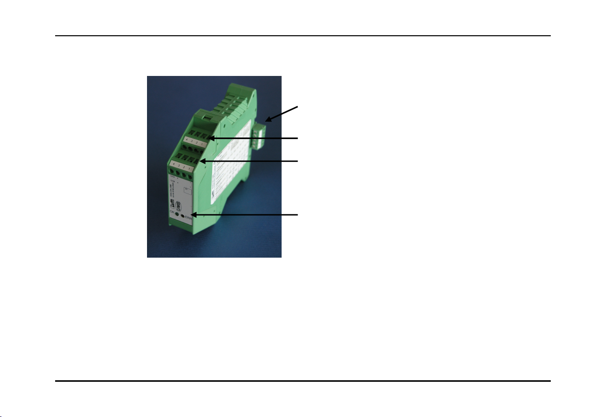
ANACON UMB ANALOGUE/DIGITAL CONVERTER ............................................................ 7
CONFIGURATION ........................................................................................................... 11
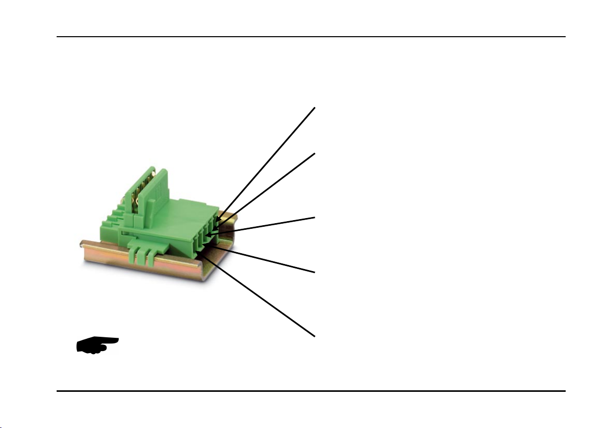
INSTALLATION AND COMMISSIONING ............................................................................... 12
SENSOR CHANNEL LIST ................................................................................................. 14
TECHNICAL DATA .......................................................................................................... 17
MAINTENANCE AND CARE .............................................................................................. 21
DISPOSAL ..................................................................................................................... 21
MANUFACTURER ........................................................................................................... 21
EC CERTIFICATE OF CONFORMITY ................................................................................. 22
Version history:
Version
Date
Compiled by
C
omments
V1 15.09.2006 EES/SH First edition
V2
1
1.01.2007
EES
Sensor c
onnection scheme for wind sensor changed; additional channels for wind speed in knots supplemented
V3
27.03.2007
EES
EC Certificate of Conformity and channels for abs. air pressure / h
umidity supplemented; grounded D
IN rail
V4
09.1
0
.2007
EES
Channel list
for precipitation and pulses changed
V5
13.07.2009
EES
Channel list for 2nd Temperature channel added
V6
25.03.2010
FS
New Housing
V7
V8
27.05.2021
27.07.2021
Sec
sec
Update Company Logo and WEEE on first page, Update Table “Measurement Variables”, Update Manufacturer,
Update about connectors, Changes table “Measurement Variables”, Resistor symbol Table “Sensor connection
scheme” improved
English Version (e)

Operating Manual UMB Analogue/Digital Converter ANACON
OTT HydroMet Fellbach GmbH, Fellbach, Germany 3

UMB Analogue/Digital Converter ANACON Operating Manual
4 OTT HydroMet Fellbach GmbH, Fellbach, Germany
Please read before use
Before using the equipment, please read the operating manual carefully and follow the instructions in every
detail.
Safety instructions
Installation and commissioning must only be carried out by suitably qualified specialist personnel.
Never take measurements on or touch live electrical parts.
Only mount the module on the DIN rail when the power is switched off.
Protect the device from direct sunlight
The equipment requires an adjustment period of several minutes on being moved to a
location with different climate conditions.
Pay attention to the technical data and storage and operating conditions.
Designated use
The equipment must only be operated within the range of the specified technical data.
The equipment must only be used under the conditions and for the purposes for which it was designed.
The safety and operation of the equipment can no longer be guaranteed if it is modified or adapted.
Guarantee
The guarantee period is 24 months from the date of delivery. The guarantee is forfeited if the designated use is
violated.

Operating Manual UMB Analogue/Digital Converter ANACON
OTT HydroMet Fellbach GmbH, Fellbach, Germany 5
Symbols used
Important indication concerning possible hazards to the user
Important indication for the correct functioning of the device

UMB Analogue/Digital Converter ANACON Operating Manual
6 OTT HydroMet Fellbach GmbH, Fellbach, Germany
Description
The UMB Analogue/Digital Converter (ANACON) is an intelligent analogue/digital converter with electrical
isolation, suitable for integration into UMB networks. The devices are easily installed on standard EN mounting
rails and networked together by means of mounting rail bus connectors. The 24V feed for the power supply
takes place via the bus connector. Windows software is available for the configuration of the ANACON via
RS232 port and an additional ISOCON (8160.UISO).
Features
2 analogue inputs with 24 bit resolution and signal conditioning for resistance, PT100/PT1000, voltage,
current, frequency and pulses as well as pre-defined settings for a large number of Lufft environmental
sensors. A half-duplex RS485 interface for networking the converters together.
Easy mounting on standard EN mounting rails
Easy networking of up to 32 subscribers via mounting rail bus connectors
24V DC power supply suitable for switchgear cabinets
ESD protection for all interfaces
Configuration via Windows software provided
Functions displayed via LED’s
Low space requirement; width approx. 23mm/module
Low energy consumption / dissipation

Operating Manual UMB Analogue/Digital Converter ANACON
OTT HydroMet Fellbach GmbH, Fellbach, Germany 7
ANACON UMB Analogue/Digital Converter
Summary
Status LED’s
Input Channel B
Input Channel A
Power supply & RS485 bus
interface

UMB Analogue/Digital Converter ANACON Operating Manual
8 OTT HydroMet Fellbach GmbH, Fellbach, Germany
Analogue Inputs Channel A and Channel B
The terminals are suitable for stranded or rigid wires
without end sleeves with cross section from 0,14 mm2
to 2,5 mm2. Alternatively, stranded or rigid wires with
end sleeves can be used with over-all cross section
from 0,25 mm2 to 2,5 mm2.
In any case the stripping length is 8 mm and the
terminals needs to be tightened with a 3,2 mm slotted
screwdriver with a torque from 0,5 Nm to 0,6 Nm.
ANACON-UMB
Connection
Channel B
Channel A
PIN Name
1 Power, Sensor Power Supply
2 ANA_+, Sense High Input
3 ANA_I, Force Low Input
4 ANA_-, Force High Input

Operating Manual UMB Analogue/Digital Converter ANACON
OTT HydroMet Fellbach GmbH, Fellbach, Germany 9
Mounting Rail Bus Connector
NOTE: The assembly must take place on a grounded DIN rail !
Earth 24V Power Supply, Feed
+24V Power Supply, Feed
B1, Internal Bus
A1, Internal Bus

UMB Analogue/Digital Converter ANACON Operating Manual
10 OTT HydroMet Fellbach GmbH, Fellbach, Germany
Status LED’s
There are 2 LED’s on the front side of the device in order to display the correct configuration and functioning of
the ANACON. Their meanings are as follows:
Red LED: - If this LED lights up permanently after switch-on there is a configuration fault.
- If this LED lights up during operation an unforeseen fault has occurred; the device must be
reset.
Green LED: - This LED flashes briefly (20ms) every 10 seconds to display the function of the device.
- This LED lights up for a longer period (>500ms) during measurement.

Operating Manual UMB Analogue/Digital Converter ANACON
OTT HydroMet Fellbach GmbH, Fellbach, Germany 11
Configuration
The ANACON modules are all supplied from the factory with ID 1. If several modules are installed in a UMB
network, it must be ensured that all modules on the network have a different ID. The following steps should be
taken in order to configure the device:
1. Clip a mounting rail bus connector onto the Din rail and connect the 24V supply with the aid of the
connector provided. Please ensure that the polarity and pin assignment are correct on connection.
Incorrect connection can cause the destruction of the ANACON module!
2. Next mount the ANACON module which you wish to configure.
3. For the connection to the RS232 port of your PC a additional ISOCON (8160.UISO) is necessary. Clip
the ISOCON also on the mounting rail and connect the module to your PC via the RS232 interface.
4. Set the desired ID and channel configuration using the UMB-Config-Tool software. You can enter the
configured ID in the inscription field on the front side of the module.
5. The ANACON is now ready for operation and can be detached from the DIN rail. Please repeat steps 2
to 5 for all additional ANACON modules.

UMB Analogue/Digital Converter ANACON Operating Manual
12 OTT HydroMet Fellbach GmbH, Fellbach, Germany
Installation and Commissioning
1. First configure all the modules using the UMB-Config-Tool configuration software in accordance with
your requirements (see Configuration chapter).
2. Clip the required number of mounting rail bus connectors onto the DIN rail and then connect all the
ANACON modules.
3. Connect the sensors to channels A and B of the ANACON module. Please note that a fixed assignment
is specified for channels A and B for the combined sensors for temperature and relative humidity as well
as the wind speed and wind direction sensors. A summary of the sensor connection scheme is provided
in the table below.
4. Now connect the 24V power supply to the mounting rail bus connectors.
5. Connect your host system to any desired ISOCON RS232 interface. The equipment is now ready for
operation.
Connecting the ANACON modules to the DIN rail
ATTENTION: Only mount or remove modules
from the DIN rail when the power is switched
off
The assembly must take place on a grounded
DIN rail!

Operating Manual UMB Analogue/Digital Converter ANACON
OTT HydroMet Fellbach GmbH, Fellbach, Germany 13
Table: Sensor connection scheme, In case of a 4-wire PT100 / PT1000 probe, one wire is not connected.
#: different cable lengths available.
8160.UANA Channel A Channel B
Input Pin1 Pin2 Pin3 Pin4 Pin1 Pin2 Pin3 Pin4
Resistance (3 wire),
PT100/ PT1000
Voltage V+ V- V+ V-
Current self-powered I- I+ I- I+
Current ANACON powered I+ I- I+ I-
Frequency F- F+ F- F+
Impulse/ Digital Input D- D+ D- D+
OttHydroMet Sensors
8160.TF# (T) red red white red red white
8353.10 (Tipping Bucket) grey pink grey pink
8160.TF#s, 8160.WST2 (T) brown green yellow
brown
green yellow

UMB Analogue/Digital Converter ANACON Operating Manual
14 OTT HydroMet Fellbach GmbH, Fellbach, Germany
Sensor Channel List
Channel assignment equipment class 6 universal measurement transmitters
UMB Channel Measurement Range
Act Min Max Avg Special Input Variable Min Max Unit
Temperature
100 120 140 160 A temperature -200.0 450.0 °C
105 125 145 165 A temperature -328.0 842.0 °F
101 121 141 161 B temperature -200.0 450.0 °C
106 126 146 166 B temperature -328.0 842.0 °F
110 130 150 170 dewpoint -200.0 450.0 °C
111 131 151 171 dewpoint -328.0 842.0 °F
Humidity
201 221 241 261 B relative humidity 0,0 100,0 %
206 226 246 266 B absolute humidity g/m²
211 231 251 271 B mixing ratio g/kg
Pressure
300 320 340 360 A air pressure 0 1200 hPa
305 325 345 365 A abs. air pressure 0 1200 hPa
301 321 341 361 B air pressure 0 1200 hPa
306 326 346 366 B abs. air pressure 0 1200 hPa

Operating Manual UMB Analogue/Digital Converter ANACON
OTT HydroMet Fellbach GmbH, Fellbach, Germany 15
Wind
Vect. avg
400 420 440 460 480 A Wind Speed 0 100.0 m/s
405 425 445 465 485 A Wind Speed 0 360.0 km/h
410 430 450 470 490 A Wind Speed 0 223.7 mph
415 435 455 475 495 A Wind Speed 0 194,4 kts
501 521 541 561 581 B Wind Direction 0 359.9 °
Precipitation
600 A precipitation absol. mm
601 B precipitation absol. mm
620 A precipitation diff. mm
621 B precipitation diff. mm
640 A precip. intens. mm/h
641 B precip. intens. mm/h
Digital input
700 720 740 760 A Digital Input 0 1
701 721 741 761 B Digital Input 0 1
Voltage
10000 10020 10040 10060 A Voltage 0 1000 mV
10001 10021 10041 10061 B Voltage 0 1000 mV
Current
10100 10120 10140 10160 A Current 0 24 mA
10101 10121 10141 10161 B Current 0 24 mA

UMB Analogue/Digital Converter ANACON Operating Manual
16 OTT HydroMet Fellbach GmbH, Fellbach, Germany
Resistance
10200 10220 10240 10260 A Resistance 0 2000 Ohm
10201 10221 10241 10261 B Resistance 0 2000 Ohm
Frequency
10300 10320 10340 10360 A Frequency 10 10000 Hz
10301 10321 10341 10361 B Frequency 10 10000 Hz
Pulses
10500 A impulse absol. 0 65520 pulse
10501 B impulse absol. 0 65520 pulse
10520 A impulse diff. 0 65520 pulse
10521 B impulse diff. 0 65520 pulse

Operating Manual UMB Analogue/Digital Converter ANACON
OTT HydroMet Fellbach GmbH, Fellbach, Germany 17
Technical Data
Power supply
Power supply 24VDC +/- 10%
Power consumption < 50mA at 24V; excluding sensor
Connection Phoenix bus connector, gold, 5 pole
Function display Green LED, flashes every 10 seconds
RS485 interface internal bus
Standard RS485 2 wire, half-duplex
Transmission type Protocol-transparent, 8 data bits, 1 stop bit, no parity
Tri-State 2 bit after stop bit edge
Transmission rate 19200 baud
Connection Phoenix bus connector, gold, 5 pole, maximum 8A
24V output max. 2 A (note the maximum current of the internal bus)

UMB Analogue/Digital Converter ANACON Operating Manual
18 OTT HydroMet Fellbach GmbH, Fellbach, Germany
Measurement Variables
Variable Measurement Range Resolution Accuracy (25°C)
Voltage 0 ... 100mV 1,526 µV +/- 200 µV
Voltage 0 ... 1000 mV 15,26 µV +/- 1 mV
Current *1) 0 ... 20 mA (max: 24mA) 305.25 nA +/- 20 µA
Current *2) 4 …20mA (max: 24mA) 305.25 nA +/- 20 µA
Resistance *3) 0 ... 200 Ohm 3.05 mOhm +/- 30 mOhm
Resistance *3) 0 ... 2000 Ohm 30.5 mOhm +/- 300 mOhm
Temperature with
PT100 *3)
-200 ... 500 °C 0.02°C for (-50°C<t<150°C)
otherwise 0.1°C
+/- 0.1°C for (-50°C<t<150°C)
otherwise +/- 0.5°C
Temperature with
PT1000 *3)
-200 ... 500 °C 0.02°C for (-50°C<t<150°C)
otherwise 0.1°C
+/- 0.1°C for (-50°C<t<150°C)
otherwise +/- 0.5°C
Frequency *4) 0 ... 1000 Hz 15.26 mHz 1 Hz
Frequency *4) 0 ... 10 kHz 152.6 mHz 10 Hz
Pulses *5) 0 ... 65520 1 pulse -
Digital input *6) 0 / 1 - -
1. Shunt resistance 51 Ohms
2. Shunt resistance 51 Ohms, voltage on Pin 1 in ANACON powered mode approx. 12V
3. If a voltage or current measurement with external power supply is used in parallel, then the minus pol of this supply has to be grounded!
4. Pulse duty ratio 50%, internal resistance approx. 500 Ohms, Uhigh>6V, Ulow<3V
5. Pulse length > 100µs, pulse spacing > 100µs, internal resistance approx. 500 Ohms, Uhigh>6V, Ulow<3V
6. Internal resistance approx. 500 Ohms, Uhigh>6V, Ulow<3V

Operating Manual UMB Analogue/Digital Converter ANACON
OTT HydroMet Fellbach GmbH, Fellbach, Germany 19
LUFFT Sensors
Sensor Measurement
Variable
Measurement
Range
Physical
Variable
Physical
Measurement
Range
Temperature Sensor 8160.TF#
or 8160.TF#s
Temperature
PT100
-50 ... 100 °C Resistance 60.34 – 138.5
Ohms
Rain Gauge with 0.2mm or
0.5mm resolution WTB100
Rain 0... 200 mm/h
Pulses 0....65620
Road temperature sensor
WST2
Temperature
PT100
-50 ... 100 °C Resistance 60.34 – 138.5
Ohms
Wind Speed and Wind
Direction 8368.01
Wind Speed 0.9 ... 50 m/s Voltage 0 - 1000 mV
Wind Direction
0 ... 358 ° Resistance 0 – 1000 Ohms

UMB Analogue/Digital Converter ANACON Operating Manual
20 OTT HydroMet Fellbach GmbH, Fellbach, Germany
Storage conditions
Permissible ambient temp. -40 ... 70°C
Permissible rel. humidity 0 ... 95% RH (non-condensing)
Operating conditions
Permissible operating temp. -30 ... 60°C
Permissible rel. humidity 0 ... 95% RH (non-condensing)
Housing
Material PA-V0, green
Width x Height x Depth 22.5 x 99 x 118.6 mm
Protection class IP20
Weight approx. 120 g
Connections COMBICON plug-in connectors 0.2 – 2.5 mm² (AWG 24 – 12)
Other manuals for 8160.UANA
2
Table of contents
Other Lufft Media Converter manuals