controlair 330 Manual

INTRODUCTION
The Type-330/335/340/345 Instrument Air Filter Regulators, Air Regulator & Filter Series are designed for air or gas service. Maximum allowable inlet
pressure is 250 psi (17 BAR). Operating temperatures are 0 to 160ºF (-620to 194ºF for Low Temperature Option). The Type-330/335/340 has low
capacity internal relief which provides very limited down stream over pressure protection. Note: Non-relieving version does not provide internal relief.
To avoid exceeding outlet pressure limits in service, a pressure-relieving or pressure-limiting device should be provided.
SPECIFICATIONS
TYPE-330 TYPE-335 TYPE-340 TYPE-345
In/Out Port Size
(Gauge Ports 1/4"
NPT)
1/4" NPT 1/2" NPT 1/4" NPT 1/4" NPT 1/2" NPT 1/4" NPT 1/2" NPT
Output Ranges
0-30 psig (0-2 bar), 0-60 psig
(0-4 bar), 0-120 psig (0-8 bar) 0-30 psig (0-2 bar), 0-60 psig
(0-4 bar), 0-100 psig (0-7 bar) 0-30 psig (0-2 BAR), 0-60 psig
(0-4 BAR), 0-120 psig (0-8 bar) N/A
Maximum Supply
Pressure
Manual Drain: 250 psig (17 bar)
Auto Drain: 150 psig (10 bar)
250 psig (17 bar)
250 psig (17 bar)
Manual Drain: 250 psig (17 bar)
Auto Drain: 150 psig (10 bar)
Mounting
Pipe, bracket or through body direct
Filter
40 micron (optional 5 micron)
None
40 micron (optional 5 micron)
Cv Values
0.5 at 150 psig
supply and 80
psig setpoint
2.5 at 150
psig supply
and 80 psig
setpoint
0.5 at 150 psig supply and 80
psig setpoint 0.5 at 150 psig
supply and 80
psig setpoint
2.5 at 150 psig
supply and 80
psig setpoint
0.5 at 150
psig supply
and 80 psig
setpoint
2.5 at 150 psig
supply and 80
psig setpoint
Exhaust Capacity
0.1 scfm (3 Nl/min) with downstream pressure 5 psig (0.3 bar) above set point
N/A
Sensitivity 1" of water N/A
Air Consumption Less than 5 scfh (2.5 Nl/min) N/A
Effect of Supply
Pressure Variation
Less than 0.25
psig (0.017 bar)
for 25 psig (1.7
bar) change
Less than 0.5
psig (0.035
bar) for 25
psig (1.7 bar)
change
Less than 0.25 psig (0.017
bar) for 25 psig (1.7 bar)
change
Less than 0.25
psig (0.017 bar)
for 25 psig (1.7
bar) change
Less than 0.5
psig (0.035 bar
)
for 25 psig (1.7
bar) change
N/A
Temperature Limits
Manual drain:
Auto drain:
Low Temp. Option:
0° to 160° F (-18° to 71° C)
32° to 160° F (0° to 71° C)
-62° to 194° F (-52° to 90° C)
-20° to 180° F (-29° to 82° C)
0° to 160° F (-18° to 71° C)
32° to 160° F (0° to 71° C)
-62° to 194° F (-52° to 90° C)
Weight
Manual drain:
Auto drain:
1.2 lb (0.54 kg)
1.42 lb (0.64kg)
1.71 lb (0.78kg)
1.65 lb (0.75 kg)
1.71 lb (0.78kg)
N/A
1.15 lb (0.52 kg)
N/A
1.38 lb (.63 kg)
N/A
1.0 lb (0.45 kg)
1.2 lb (0.54 kg)
1.5 lb (0.68 kg)
1.5 lb (0.68 kg)
Operating Media Air, Inert Gas & Sweet Natural
Gas Air, Inert Gas & Sweet or Sour
Natural Gas Air, Inert Gas & Sweet Natural
Gas Air, Inert Gas & Sweet Natural
Gas
MATERIALS
Body
Diecast Aluminum Alloy, Irridite and Baked Epoxy Finish
Filter Polyethylene Polyethylene None Polyethylene
Diaphragm
Nitrile Elastomer and Nylon Fabric
Low Temp. Option: Silicone and
Nitrile
Viton
Nitrile Elastomer and Nylon Fabric
Low Temp. Option: Silicone and
Nitrile
N/A
Valve Seat
Nitrile Elastomer
Nitrile Elastomer
Nitrile Elastomer
Additional
Materials
Brass, Zinc Plated Steel, Acetal Brass, Zinc Plated Steel, Acetal
INSTALLATION
1. Install the regulator/filter as close as possible to the instrument or tool it is to service.
2. Clean all pipelines to remove dirt and scale prior to installation.
3. Install the regulator/filter so that the direction of flow is from the “IN” to “OUT” connection as marked on the body of the regulator/filter.
4. For best drainage, orient the drain valve so that it is at the lowest point on the drip well housing. Positioning of the drain valve may be
improved by rotating the drip well with respect to the body.
5. The exhaust port should be kept free and unplugged. Rotating the bonnet relative to the body may change the vent hole orientation.
Installation, Operation and Maintenance Instructions
Type-330 Filter Regulator
Type-335 NACE Filter Regulator
Type-340 Regulator
Type-345 Filter

Page 2
6. Exhaust may be remotely vented by installing tubing to the 1/4” NPT port. (E Option)
7. Apply pipe compound or sealing tape to the mail pipe threads prior to installing regulator/filter. Use caution to prevent the sealant from getting
inside the regulator/filter.
OPERATION
1. Prior to turning on supply air, back off adjusting screw until there is no compression of the range spring.
2. After applying the air supply, outlet pressure will be increased by rotating the adjustment screw clockwise. Pressure can be decreased by
turning counter clockwise.
3. Tighten locknut to maintain desired pressure setting.
MAINTENANCE
1. To remove condensate, from the Type-330/335/345, slowly open drain valve by turning clockwise and bleed accumulated liquid.
2. To clean filter element (Type-330/335/345)
a) Shut off supply pressure and relieve all internal pressure.
b) Drain condensate from drip well.
c) Remove four corner bolts from bottom of unit and remove drip well housing.
d) Remove filter retaining screw.
e) Remove filter retainer, filter o-ring seals and filter.
f) Clean parts and reassemble in reverse order.
3. To clean/replace pintle assembly
a) Follow steps (a) through (d) above.
b) Unscrew collar and remove. (1/2” NPT only)
c) Remove pintle spring. The Type-340 does not contain a filter or collar. The pintle and pintle spring will be accessible upon removal
of base.
d) Clean or replace parts as required. Apply a high quality lubricant to all cleaned or replaced o-ring seals.
e) Reassemble in reverse order.
4. To clean/replace diaphragm assembly
a) Back out the adjusting screw until the spring is no longer compressed.
b) Remove the four bonnet screws and separate the bonnet from the body of the regulator. Remove the spring guide and spring.
c) Remove the diaphragm assembly, clean or replace it as necessary and reassemble in reverse order. After placing the diaphragm
assembly on the body, push down the assembly to make sure that the pintle is seated properly and strokes smoothly.
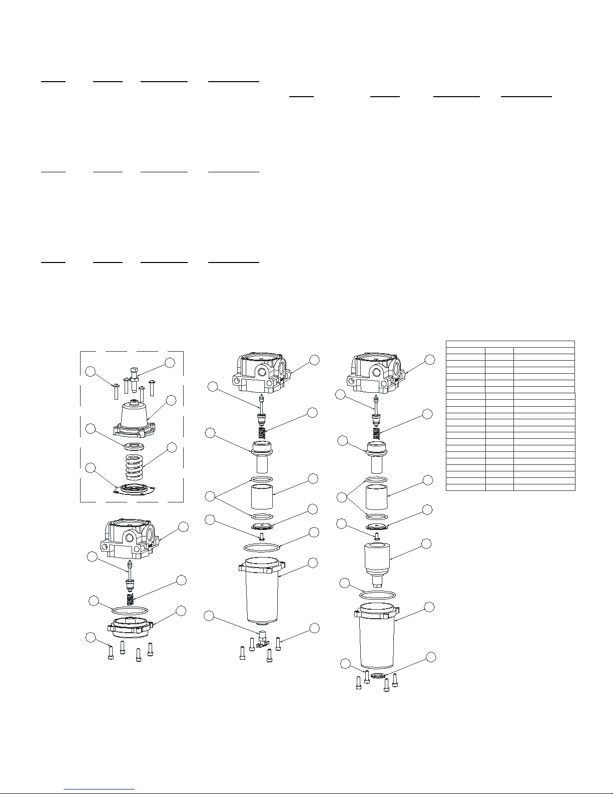
5. Repair kits/replacement parts
a) Repair kits include all parts marked with an asterisk (*).
b) Order kit as described in exploded view below
c) Shut off supply air. Back out adjusting screw
d) Remove four corner bolts from bottom of the unit and four screws on top and remove all parts.
e) Replace all parts that show excessive wear. Apply a high quality lubricant to all cleaned or replaced o-ring seals.
f) Clean all parts and replace in reverse order
WARNING:Only qualified personnel should install or service a regulator. Regulators should be installed, operated, and maintained in
accordance with international and applicable codes and regulations, and ControlAir instructions. If the regulator vents fluid or a leak
develops in the system, it indicates that service is required. Failure to take the regulator out of service immediately may create a
hazardous condition. Personal injury, equipment damage, or leakage due to escaping fluid or bursting of pressure-containing parts may
result if this regulator is over pressured or is installed where service conditions could exceed the limits given in the Specifications section,
or where conditions exceed any rating of the adjacent piping or piping connections. To avoid such injury or damage, provide pressure-
relieving or pressure-limiting devices (as required by the appropriate code, regulation, or standard) to prevent service conditions from
exceeding limits. Additionally, physical damage to the regulator could result in personal injury and property damage due to escaping fluid.
To avoid such injury and damage, install the regulator in a safe location. The internal relief valve in the Type-330 regulators does not
provide full overpressure protection. The internal relief valve is designed for minor seat leakage only.
WARNING:To avoid personal injury resulting from sudden release of pressure, isolate the regulator from all pressure before attempting
disassembly.
WARNING:To avoid personal injury, property damage, or equipment damage caused by sudden release of pressure or explosion of
accumulated gas, do not attempt any maintenance or disassembly without first isolating the regulator from system pressure and relieving all
internal pressure from the regulator.
WARNING:The materials of the Type-330/335/340/345 are compatible with natural gas. The user should be warned, however, that the
Type-330/335/340 regulator/filter may vent some gas to the atmosphere. In hazardous or flammable service, vented gas may accumulate
and cause personal injury, death, or property damage due to fire or explosion. If regulator is used in a hazardous gas service area, the
regulator must be vented to a remote, safe location away from air intakes or any other hazardous area. The vent line or stack
opening must
be protected against conden
sation or clogging. Do not use these products where pressure and temperatures can exceed those listed under
specifications.

Page 3
REPAIR KITS
Model
Porting
Description
Part Number
REPLACEMENT FILTERS
Type 330
1/4" NPT
Relieving
449-871-100
Model
Porting
Description
Part Number
Type 330
1/4" NPT
Non-relieving
449-871-101
Type 330/335/345
1/4" NPT
40 micron
446-777-001
Type 330
1/2" NPT
Relieving
449-871-113
Type 330/335/345
1/4" NPT
5 micron
446-777-002
Type 330
1/2" NPT
Non-relieving
449-871-114
Type 330/335/345
1/2" NPT
40 micron
446-777-024
Type 330/335/345
1/2" NPT
5 micron
446-777-025
Model
Porting
Description
Part Number
Type 340
1/4" NPT
Relieving
449-871-115
Type 340
1/4" NPT
Non-relieving
449-871-116
Type 340
1/2" NPT
Relieving
449-871-117
Type 340
1/2" NPT
Non-relieving
449-871-118
Model
Porting
Description
Part Number
Type 335
1/4" NPT
NACE
449-871-134
Type-330/340/345 1/2" NPT Units
1
2
1 1 ADJUSTING SCREW ASS'Y
2 4 10-24 BUILD SCREW
3 1 BONNET
4 1 SPRING GUIDE
5 1 RANGE SPRING
6 1 DIAPHRAGM ASS'Y
Parts List
ITEM QTY DESCRIPTION
3
4
5
6*
7 1 BODY
8 1 VALVE ASS'Y
9 1 VALVE SPRING
10 1
COLLAR
11 1
SEAL, FILTER
77
8*
8*
99
13 13
14* 14*
15* 15*
16 16
17 17
10*
10*
18
18
19
12
21
20
12
12 4
13 1
FILTER
14
FILTER RETAINER
15 2
1
O-RING
DRIPWELL
SCREW, RETAINER
17
18 1
1DRAIN VALVE
16
10-24 DRIPWELL SCREW
1
19 1AUTODRAIN VALVE
20 1NUT, AUTODRAIN VALVE
21 1
BASE ASS'Y
340 1/2 NPT 330 1/2 NPT 330 1/2 NPT A.D.
7
8*
9
10*
12
11
COMMON TO ALL UNITS
*
INCLUDED IN REPAIR KIT
330/345 ½” NPT 330/345 ½” NPT A.D.

8 Columbia Drive, Amherst, New Hampshire 03031 U.S.A.
Tel: (603) 886-9400 Fax: (603) 889-1844
441-622-100 (11/06/17) www.controlair.com Page 4
Type-330/335/340/345 1/4" NPT Units
1
2
1 1 ADJUSTING SCREW ASS'Y
2410-24 BUILD SCREW
31BONNET
41SPRING GUIDE
5 1 RANGESPRING
61DIAPHRAGM ASS'Y
Parts List
ITEM QTY DESCRIPTION
71BODY
81PINTLE
91PINTLE SPRING
10 1
FILTER
11 1
FILTERRETAINER
12 4
13 1
O-RING
14 DRIPWELL
15 1
10-24 DRIPWELL SCREW
1DRAIN VALVE
3
4
5
6*
7
8*
9*
13*
14
10 *
15
16
12
17
18
19
20
21
7
7
9*
9*
12
12
11
10*
10 *
13*
8*
8*
16 1GASKET
17 1FILTER RETAINER
18 1AUTODRAIN VALVE
19 1DRIPWELL A.D.
20 1NUT, AUTODRAIN VALVE21 1
COMMONTOALLUNITS
BASE ASS'Y
340 1/4 NPT 330 1/4 NPT 330 1/4 NPT A.D.
*
INCLUDED IN REPAIR KIT
LIMITED WARRANTY & DISCLAIMER
ControlAir, Inc. products are warranted to be free from defects in materials and workmanship for a period of eighteen months from the date of
manufacture, provided said products are used according to ControlAir, Inc. recommended usages. ControlAir, Inc.’s liability is limited to repair of, refund
of purchase price paid for, or replacement in kind of, at ControlAir, Inc.’s sole option, any products proved defective. ControlAir, Inc. reserves the right to
discontinue manufacture of any product or change product materials, design or specifications without notice. Note: ControlAir does not assume
responsibility for the selection, use, or maintenance of any product. Responsibility for the proper selection, use, and maintenance of any ControlAir
product remains solely with the purchaser and end user.
330/335/340 ¼” NPT 330/335/340/345 ¼” NPT A.D.
This manual suits for next models
3