Controll-A-Door S series User manual

www.bnd.com.au
B&D Doors is a division of B&D Australia Pty Ltd
ABN 25 010 473 971
S
Controll-A-Door®S
Instruction Manual
Sectional Door Opener
Manufacturer’s Part # 79079 (Manual) V1.02

Safety Rules 03
Default Settings & Specifications 04
About Your Opener 05
Operating Controls 06
Kit Contents 08
Installation 09
C-Rail Attachment 09
Determine Door Type 10
Mounting - Track Type Door 11
Mounting - Non-Track Type Door 12
Mounting Door Bracket & Arms 13
Programming the Opener 14
Setting Travel Limits - Control Panel 14
Testing Safety Obstruction Force 15
Safety Obstruction Force Test 15
Adjusting Safety Obstruction Forces 15
Coding Transmitters 16
For Door Operation 16
For Courtesy Light Operation 16
For Vacation Mode 17
For Auxiliary Output 17
For Pet (Pedestrian) Mode 18
Deleting All Transmitter Codes 18
Mounting Wall Transmitter 18
Accessories 19
Terminal Block 19
Remote Aerial 19
Electric Key Switch 19
Safety Infra-red Beam 20
Battery Back Up Installation 21
Solar Power System Installation 22
How To Use Your Opener 24
Transmitter Battery 24
Locking 24
Manual Release 24
Power Failure 24
Safety Infra-red Beam 25
Courtesy Light 25
Auxiliary Output 25
Vacation Mode 25
Setting The Pet Mode Position 25
Maintenance 26
Troubleshooting Guide 27
Parameters 28
Spare Parts 30
Warranty 32
Controll-A-Door®S
Sectional Door Opener
Controll-A-Door®S Instruction Manual2

Safety Rules
Please read these important safety rules
These safety alert symbols indicate a personal safety or property damage
instruction exists. READ THESE INSTRUCTIONS CAREFULLY.
This automatic garage door opener is designed and tested to offer safe
service provided it is installed and operated in strict accordance with the
following safety rules. Failure to comply with the following instructions may
result in death, serious personal injury or property damage.
CAUTION: If your garage has no pedestrian entrance
door, an emergency access device should be installed.
This accessory allows manual operation of the garage
door from outside in case of power failure.
Position the Garage Door Opener so that the power plug
is accessible when inserted into the power outlet (EN
60335-1).
This opener should be installed in accordance with relevant
Australian Standards.
Do not allow children to play with door controls.
Keep transmitters away from children.
Watch the moving door and keep people away until the
door is completely opened or closed.
Activate the opener only when the garage door is in full
view, free of obstructions and with the opener properly
adjusted.
Keep the garage door balanced. Sticking or binding
doors must be repaired. Garage doors, door springs,
brackets and their hardware are under extreme tension and
can cause serious personal injury. Do not attempt any garage
door adjustment. Do not use if repair or adjustment is needed.
Call for professional garage door service.
Install the optional wall transmitter in a location where the
garage door is visible, but out of the reach of children at
a height of at least 1.5m.
Disconnect electric power to the garage door opener
before removing covers.
Doors requiring over 400N of force to move must have
Safety Infra-red Beams fitted.
Do not wear rings, watches or loose clothing while
installing or servicing a garage door opener.
This opener is not suitable for commercial, industrial
or common entry applications.
To avoid serious personal injury from entanglement,
remove all unnecessary ropes or chains and disable
any equipment such as locks which are not needed for
powered operation.
Installation and wiring must be in compliance with
your local building and electrical codes. Connect
the power cord only to properly earthed mains. If an
extension lead must be used, make sure it is a 3-core lead
and approved to 7 amp capacity.
If the power cord is damaged, it must be replaced
by the manufacturer, its service agent or a similarly
qualified person in order to avoid a hazard.
This opener is a plug in domestic appliance and is
designed for indoor use only. It must be installed in
a dry position that is protected from the weather.
The opener is not intended for use by young children
or infirm persons without supervision.
B&D Doors to the extent that such may be lawfully excluded hereby expressly disclaims all conditions or warranties, statutory or otherwise which may be implied by laws as
conditions or warranties of purchase of a B&D Garage Door Opener. B&D Doors hereby further expressly excludes all or any liability for any injury, damage, cost, expense or claim
whatsoever suffered by any person as a result whether directly or indirectly from failure to install the B&D Garage Door Opener in accordance with these installation instructions.
WARNING! It is vital for the safety of
persons to follow all instructions. Save
these instructions.
D Power Drive : Instruction Manual
© Copyright 2009 B&D Doors
3Controll-A-Door®S Instruction Manual

Default Settings & Specifications
Factory default settings
Default Step Minimum Maximum
Courtesy light time 3 minutes
10 Sec in battery
backup mode
- 3 minutes
10 Sec in battery
backup mode-
3 minutes
10 Sec in battery
backup mode-
Obstruction force margin 0.7 amps 0.1 amps 0 2.0 amps
Technical specifications
Power supply 230V - 240Va.c. 50Hz
Transformer rating 24Vd.c.
Standby power 2.2 Watts
Motor power 100 Watts
Motor type 24Vd.c permanent magnet
Shuttle travel distance in the C-Rail 2.7m approx. (standard)*
Maximum shuttle travel distance in the C-Rail 3.750 m (with one extension)*
Maximum door opening: Width:
Height:
Weight:
5500mm (16.5m2)
2150mm
100kg
Minimum headroom 25mm
Short term peak force 700N (70kg)
Lift force 450N (45kg)
Nominal force 150N (15kg)
Receiver type UHF Multi-frequency FM Receiver
Receiver code storage capacity 8 X 4 button Transmitter Codes
Transmitter frequency 433.47, 433.92, 434.37 MHz
Coding type Tri-Tran™
Number of code combinations Over 4.29 billion random codes
Code generation Non-linear encryption algorithm
Transmitter battery CR2032 (3 Volts)
Courtesy light Festoon style lamp 24 volts 15 watt
Controller fuse 10A slow blow
*The actual travel of the door depends on configuration of the connecting arms.
Note: Intermittent operations may occur in areas which experience very strong winds. The strong wind puts extra pressure
on the door and tracks which may in turn intermittently trigger the safety obstruction detection system.
Controll-A-Door®S Instruction Manual4

Thank you for choosing a Controll-A-Door® S automatic
garage door opener, designed and developed in Australia
by B&D Doors.
The technically advanced construction of this opener
ensures you enjoy the following benefits:
Warranty
Five (5) year/10,000 cycles full parts and labour warranty
on motor, electronics and mechanical components of
the opener when installed by an Approved B&D Dealer
(conditions such as annual garage door servicing apply).
Tri-Tran Frequency Hopping Technology
Every time a transmitter is used, it simultaneously sends a
signal over three different frequencies, reducing the chance
of interference from other radio frequency sources.
Code Hopping Technology
Every time a transmitter is used a new security code
is generated from over 4.29 billion possible code
combinations. This greatly enhances the security of the
system and makes “code grabbing” a thing of the past!
Multi-Channel Transmitter
Multi-channel transmitters allow you to operate other
devices such as an adjoining garage door or automated
gate from the same handy unit.
Warranty Expired Indicator
The opener will indicate that the number of cycles covered
by the warranty has been reached by flashing the courtesy
light 10 times after each operation. This flashing will
continue for 20 cycles unless it is reset by pressing the SET
button while the courtesy light is flashing.
S-ALPS (Semi Automatic Limits Positioning
System)
The S-ALPS system does away with manual adjustment of
the door’s limits position using mechanical parts, such as
cams and microswitches.
Safety Reversing System
The automatic safety reverse system significantly reduces
the risk of death or serious injury if trapped by a closing door.
The safety reverse force can be adjusted for environmental
conditions such as windy areas.
Courtesy Light
The courtesy light automatically switches on for
approximately three (3) minutes when operating the door.
This can also be programmed to turn on and off from a
transmitter.
Battery Back Up
Optional Battery Back Up or solar power is available.
Memory Retention
In case of a power failure the opener does not lose the
transmitter codes or limit settings.
Soft Start/Soft Stop
The opener eases into and out of each cycle making
for smoother and quieter operation, as well as reducing
wear and tear on the door and opener.
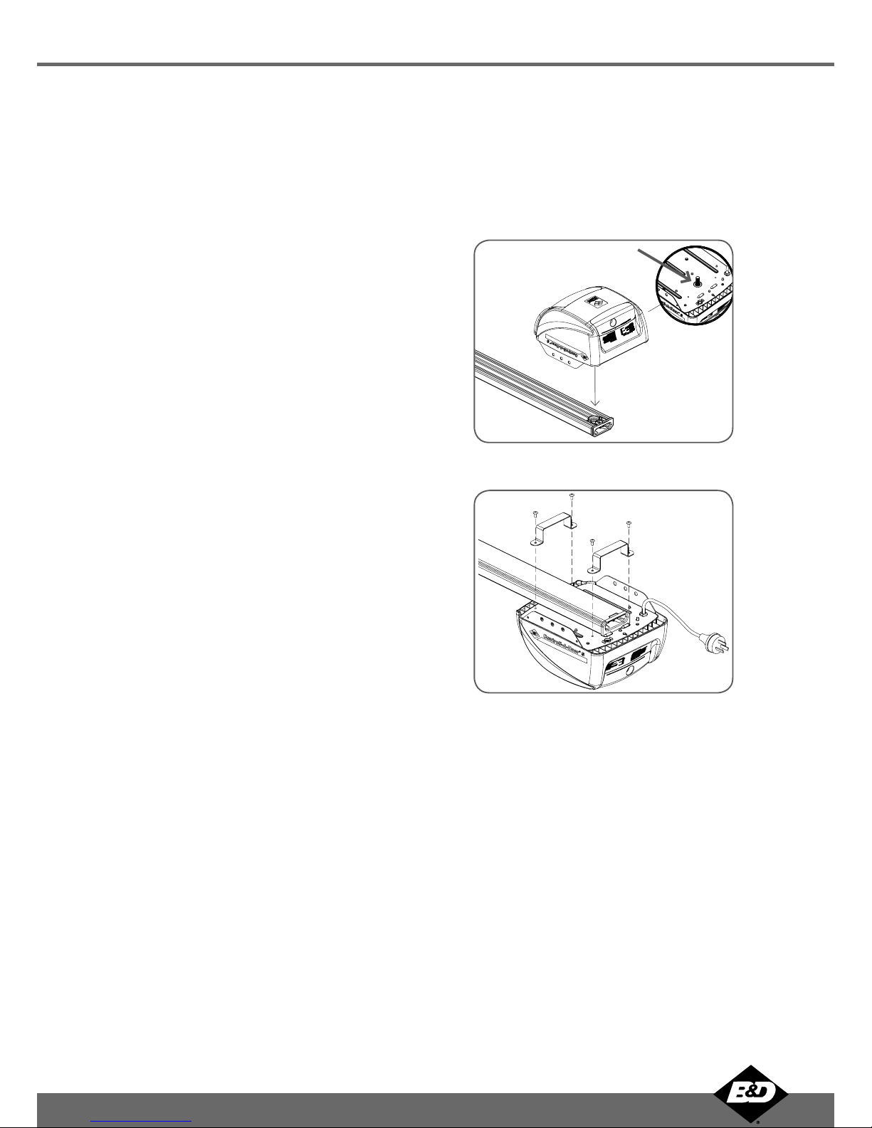
Manual Release
The manual release handle allows the door to be
operated by hand in the event of a power failure.
Self Locking
There is no need to manually lock your garage door, as
the opener ‘positively’ locks the door when closed.
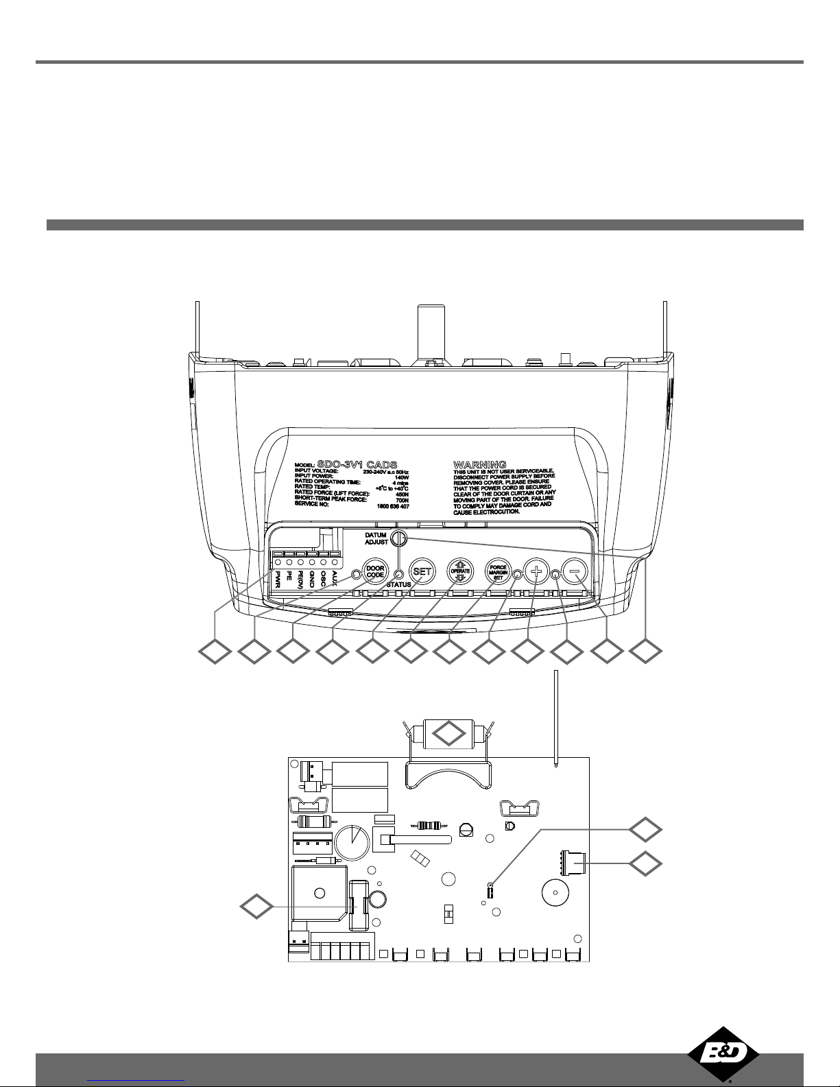
Periodic Maintenance Indicator
The SERVICE LED will illuminate to indicate that
periodic maintenance is required. Contact your dealer/
installer for service.
Service Fault Indicator
Flashing LEDs on the control panel easily identify
operational problems or service requirements.
Dynamic Door Profiling
Changing door characteristics are automatically
compensated for and “learnt” with each operation of
the door.
External Aerial
An external aerial can be connected for sites where
radio reception is a problem.
Vacation Mode
A transmitter can be programmed to disable the
garage door opener radio receiver. This is ideal if the
door is to be left idle for prolonged periods.
Pet (Pedestrian) Mode
A transmitter can be programmed to open the door
partially to allow pets access to the garage. The door
opening height is adjustable via a handheld programmer.
Auxiliary Output
You can program a spare button on your transmitter to
operate this output, which can control items that use a
momentary close switching mechanism.
About Your B&D Opener
D Power Drive : Instruction Manual
© Copyright 2009 B&D Doors
5Controll-A-Door®S Instruction Manual

Operating Controls
Terminal Block:
24V PWR is used to power devices such as Safety Infra-red Beams and external receiver (100 milliamp max).
P.E(IR) input is used to connect to Safety Infra-red Beam.
P.E(IR) 0V is a 0 volt connection for Safety Infra-red Beam.
GND is a common -ve ground for accessories
OSC is used for the connection of a wired switch (momentary contact). This switch can then be used to open, stop
or close the door. Install the wall switch in a location where the switch is out of reach of children and the garage door
is visible.
AUX OUT This function allows the opener to operate other devices such as external lights, or an alarm system.
CODING LED (red) light flashes when a code is being stored or when a transmitter button is pressed.
DOOR CODE button is used for storing or erasing transmitter buttons for door operation
SERVICE LED (Yellow) indicates when the opener requires service or repairs.
SET button (Orange) is used during the installation phase together with the Open and MINUS (-) buttons to set the door
limit positions. The Set button is also used to re-initialize the Opener.
OPERATE button (Yellow) is used during installation to test the open, stop and close cycles for the opener. The opener
has to be initialised by the SET button to make the OPERATE button operable.
FORCE MARGIN SET Button: The obstruction force margin is set automatically during installation. The margin can be
adjusted manually using the Force Margin Set button (White). Holding the Force Margin Set button and pressing PLUS
(+) or MINUS (-) buttons will increase or decrease the amount of force. The Force Margin Set should only be used if
environmental factors (wind, etc.) affect the door’s operation.
OPEN LIMIT LED (green) the LED is very helpful during installation. It illuminates and flashes when the door is opening
and remains steady on when the open limit position has been reached.
PLUS (+) button (green) is used during installation to help set the open limit position. Pressing and holding this button
will move the door in the open direction, releasing stops the door.
NOTE: The safety obstruction detection is inoperable when the PLUS (+) button is used to move door.
CLOSE LIMIT LED (red) the LED is very helpful during installation. It illuminates and flashes when the door is closing
and remains steady on when the close limit position has been reached.
MINUS (-) button (red) is used during installation to help set the close limit position. Pressing and holding this button
will move the door in the close direction. Movement stops when the button is released.
NOTE: The safety obstruction detection is inoperable when the CLOSE button is used to move door.
DATUM ADJUST SCREW is used during limits set up to indicate the mid point of the door’s travel.
10A FUSE
PROG INPUT is used to connect the Handheld “PG-3” Programmer for editing control and receiver functions, accessing
diagnostic tools, and activating special features and operating modes.
JP1 SOLAR CONNECTOR the shunt must be fitted for solar operation.
COURTESY LIGHT 15 watts 24 volts festoon type globe is used for courtesy light
01.
02.
03.
04.
05.
06.
07.
08.
09.
10.
11.
12.
13.
14.
15.
16.
Controll-A-Door®S Instruction Manual6

Fig. 01
01
16
02 03 04 05 06 07 08 09 10 11 12
13
14
15 Fig. 02
D Power Drive : Instruction Manual
© Copyright 2009 B&D Doors
7Controll-A-Door®S Instruction Manual

Kit Contents
Powerhead Unit (Fig. 03)
1 x Controll-A-Door®S powerhead
1 x Transmitter pack
(Pack includes one TB-2 and one TB-4 keyring
transmitters with batteries)
1 x Wall mount transmitter with battery
2 x Door attachment arms
1 x Accessory and hardware pack
1 x Installation Manual
Single Piece C-Rail with Pre-Assembled Chain
(Fig. 04)
NOTE: Chain in one piece rail has been tensioned by the
factory. Do not adjust the tension of the chain.
IMPORTANT NOTE: If a modification to the length of the
track is required, the adjustment must be made from the
powerhead end only.
Fig. 03
Fig. 04
PLUS
Controll-A-Door®S Instruction Manual8

Installation
C-Rail Attachment
Step 1 - Attach C-Rail to Powerhead
Locate and insert the powerhead’s shaft into the C-Rail’s
sprocket as shown in (Fig. 05).
Step 2 - Secure C-Rail to Powerhead
Fix the two track brackets as shown in (Fig. 06). Fix with
the four screws supplied in accessory pack.
Locate shaft into
sprocket
Shaft
Screw M4 X 8
Tr a ck bracket (x2)
Fig.06
Fig. 05
D Power Drive : Instruction Manual
© Copyright 2009 B&D Doors
9Controll-A-Door®S Instruction Manual

Fig. 9
Fig. 8
Fig. 7
Determine the Door Type
Step 3 - Determine the Door Type
Determine which type of garage door you have as illustrated
in (Fig. 7) to (Fig. 9).
For a sectional (panel) door on tracks (Fig. 7)
proceed with the installation from Step 4.
For a one piece door on tracks (Fig. 8)
proceed with the installation from Step 4.
For a one piece door without tracks (on springs) (Fig. 9)
proceed with the installation from Step 8 (page 12).
Proceed from Step 4
Door
Tra ck
Sectional door with track
One piece door with track
Door
Tra ck
Door
Proceed from Step 4
Proceed from Step 8 on page 12
One piece door without track
Controll-A-Door®S Instruction Manual10

Tra ck
Door
Tra ck
Level
Level
Door
Drilled holes
Structural member
Fig. 13
Fig. 12
Fig. 11
Fig. 10
Mounting - Track Type Door
Step 4 - Determine Bracket Position
Open the door and find the highest point of travel of
the top door panel.
Using a level, transfer this height to the wall above the
door (Fig. 10) and mark a line 60mm above it.
Determine the centre point on the wall above and on
top of the door. Then draw two (2) lines extending
21.5mm from each side of the centre point. (Fig. 11)
Step 5 - Mounting the Wall Bracket
Centre the bracket over the intersection of these two
lines. Mark centres for at least two holes (Fig. 11).
Ensure a solid mounting point is behind
these holes.
Drill holes into the wall with an appropriate sized bit.
Secure bracket to the wall using:
IF CONCRETE OR BRICK - 8mm or 5/6 loxins or
dynabolts.
IF TIMBER - wood screw #20 or equivalent
(minimum 50mm long).
WARNING: Make sure concrete, brick wall
or timber lintels are solid and sound so as to
form a secure mounting platform.
Step 6 - Attach the C-Rail to the Wall Bracket
Attach the C-Rail assembly to the wall bracket with the
90mm long clevis pin and secure with the supplied
snap pin (Fig. 12).
Leave the powerhead in its packing box for protection
during installation.
Step 7 - Securing the Powerhead to the Ceiling
Raise the powerhead from the packing box and
support it in the horizontal position with a step ladder.
Open the garage door. Rest the opener on the open
door and use a scrap piece of wood to bring it to
horizontal level.
Line up the track perpendicular to the wall.
Secure the perforated angle (not supplied) to the
ceiling above where powerhead’s mounting holes will
be once fully installed. A representative mounting is
shown (Fig. 13).
Connect the powerhead to the ceiling mounted
perforated angle with M8x20mm screws and nuts.
Strips should not extend more than 18mm below
centre of powerhead mounting holes (Fig. 13).
For an alternative mounting option, go to Step 10.1
WARNING: The opener must be securely
fastened to structural supports, otherwise
opener failure may ensue causing serious
personal injury and/or property damage.
a.
b.
c.
a.
•
b.
c.
a.
b.
a.
b.
c.
d.
e.
43
21.5
21.5
D Power Drive : Instruction Manual
© Copyright 2009 B&D Doors
11Controll-A-Door®S Instruction Manual

Centre of door
Step
Ladder
Step
Ladder
C rail
Door
Highest point
of door travel
Fig. 16
Fig. 15
Fig. 14
Fig. 17
Mounting - Non Track Type Door
WARNING: Make sure concrete, brick wall
or timber lintels are solid and sound so as to
form a secure mounting platform.
Step 8 - Determine the Door’s Centre
Find the centre of the door and mark this location both
above the door and on top of the door.
Draw two lines 21.5mm either side of this (Fig. 14).
Step 9 - Prepositioning the Opener
Raise the door to open position.
Rest the opener on the top edge of the door with end
of the C-Rail against the wall (Fig. 18).
Support the powerhead level with the lowest point of
the open door (Fig. 15).
NOTE: Do not slide C-Rail along the face of the door.
Step 10 - Mounting the C-Rail
Close the door slowly. The C-Rail will be elevated by
the top edge of the door as it moves.
Stop the door when it is at its highest point of travel.
Allow 25mm additional height for clearance between
the door and the track (Fig. 16).
Support the C-Rail in this position and close the door
The height determined in Step 11(b) will be the height
at which to mount the wall bracket.
Centre the bracket along the line determined in Step 9.
Using the bracket as a template, mark a minimum
of two holes and drill with appropriate size bit. For a
more secure fitting, the wall bracket can be anchored
using more than two holes.
Secure the bracket to the wall using:
IF CONCRETE OR BRICK - 8mm or 5/6 loxins or
dynabolts.
IF TIMBER - wood screw #20 or equivalent
(minimum 50mm long).
Attach the wall bracket to the C-Rail with the 90mm
long clevis pin (Fig. 17) and secure by a snap pin.
Step 11 - Securing the Powerhead to the Ceiling
Secure the perforated angle (not supplied) to the
ceiling above where powerhead’s mounting holes will
be. See (Fig.13) for a representative mounting.
Connect the powerhead to the ceiling mounted
perforated angle with M8x20mm screws and nuts.
Strips should not extend more than 18mm below
centre of powerhead mounting holes (Fig. 13).
WARNING: The opener must be securely
fastened to structural supports, otherwise
opener failure may ensue causing serious
personal injury and/or property damage.
a.
b.
a.
b.
c.
a.
b.
c.
d.
e.
f.
g.
h.
a.
b.
Controll-A-Door®S Instruction Manual12

Fig. 18
Fig. 19
Fig. 20
Fig. 21
Mounting Door Bracket and Arms
Step 11.1 - Alternative Mounting Option
The opener can be fastened to the roof by driving a bolt
through the C-Rail into a structural timber support. The bolt
head’s height must not exceed 6mm (Fig. 18).
Step 12 - Mounting Door Bracket
The door bracket comes in two parts. The bottom plate
with two mounting holes is used on its own for one piece
doors. For sectional doors, the top plate is placed over the
bottom plate and is fixed with four (4) screws (Fig. 19).
Mount the door bracket, or bracket assembly, on the
door’s centre line one-third down the top panel (Fig.
19) using M6 or equivalent screws (not supplied),
STEEL DOORS ONLY: Bracket can be welded in
place.
NOTE: If in doubt about the door’s strength,
reinforcement may be added to the door’s
frame where necessary. Door damage may
occur if the bracket is installed on a panel
with insufficient strength. The opener’s
warranty does not cover damage caused to
the door and/or door panels.
Step 13 - Attaching the Arms
FOR SECTIONAL AND ONE PIECE DOORS WITH TRACK:
Assemble the bent and straight arms with bolts
and nuts supplied in the accessory pack (Fig. 20).
Always use both bent and straight arms.
Connect the assembled arm to the bracket and the
disengaged trolley with clevis and snap pins. The
angle “A” must be more than 10° (Fig. 20).
WARNING: Connecting the bent arm other
way around may damage the door.
FOR ONE PIECE DOORS WITHOUT TRACK
Assemble the bent and straight arms as shown in (Fig.
21) with bolts and nuts supplied in the accessory
pack. Always use both the bent and straight arms.
Connect the assembled arm to the bracket and the
disengaged trolley with clevis and snap pins.
If installing on a door with a bad wave action,
lengthening the arm will assist in reducing this effect.
IMPORTANT NOTE - If the manual release
handle is more than 1.8 metres from floor level
when the opener is installed, extend the handle
to a height less than 1.8 metres.
a.
b.
a.
b.
a.
b.
c.
Ceiling
Steel rail
Shuttle assembly
Drill hole at centre of
track (recommended bolt
size M6 or M8)
The height of bolt
head must not
exceed 6 mm
10
0
A
D Power Drive : Instruction Manual
© Copyright 2009 B&D Doors
13Controll-A-Door®S Instruction Manual

Setting Travel Limits
IMPORTANT NOTE: The OPERATE button
will not function until the open and close limit
positions are set.
NOTE: The door and shuttle must be engaged
into the chain index. The door should be open
approximately half way.
Note: If Safety Infra-Red Beam are to be used
they must be installed before setting the travel
limits.
Step 14.1 - Setting Limits Positions
Remove the controls cover to access the controls panel as
shown in (Fig. 22). Replace it when setup is completed.
Step 14.2 - Connect Power to the Drive unit
Plug the power cord into a mains point and switch power
on. The red CLOSE LIMIT LED will be flashing.
WARNING: The safety obstruction detection
system is inoperable while MINUS (-) and
PLUS (+) drive buttons are being used and
travel limits are not set.
Step 14.3 - Set the Datum Position
Press and hold the MINUS (-) or PLUS (+) buttons to
move the door to the halfway position. Ensure that the
door, shuttle and chain index are engaged.
Using a small screwdriver, turn the DATUM ADJUST
screw until the STATUS LED comes on (Fig 23).
Note: If the STATUS LED is already illuminated when the
door is halfway up, turn the DATUM ADJUST screw until
the light goes off, then turn back one notch to illuminate
again.
Step 14.4 - Set the Limits Positions
Press and hold the MINUS (-) button until the door
reaches the desired close limit position. Single presses
will inch the door closed (Fig 24).
Press the SET button to store the close position into
memory (Fig. 24).
Press and hold the PLUS (+) button until the door
reaches the desired open limit position. Single presses
will inch the door open (Fig. 24).
WARNING: The door will automatically close,
open and close again once Step 12.4(d) is
performed. Ensure that no persons or objects
are in the door’s path.
Press the SET button to store the open position into
memory (Fig. 24).
The door will now automatically close and open to
calculate the safety obstruction settings. After this, the
opener can be operated with the OPERATE button.
a.
b.
a.
b.
c.
d.
e.
Fig. 24
Fig. 23
Fig. 22
Controll-A-Door®S Instruction Manual14

Testing Safety Obstruction Force
CAUTION: Take care when testing the safety
obstruction force. Failure to follow this
warning can result in serious personal injury
and/or property damage.
Step 15.1 Test the Close Cycle
Press the OPERATE button to open the door (Fig. 25).
Place a piece of timber approximately 40mm high on
the floor directly under the door (Fig 26).
Press the OPERATE button to close door.
The door should strike the object and re-open.
Step 15.2 Testing the Open Cycle
Press the OPERATE button to close the door (Fig. 25).
Press again to open the door.
When the door reaches approximately half way, firmly
grab the door’s bottom rail - the door should stop.
If the door does not reverse readily when closing, or stop
when opening, the force may be excessive and need
adjustment, refer to Step 13.4.
IMPORTANT WARNING: If the door is closing
and is unable to re-open when obstructed,
discontinue use. Do not use a door with faulty
obstruction sensing. Repair fault and re-test
before using.
Adjusting Safety Obstruction Force
The safety obstruction force is calculated automatically
and normally does not require adjustment. The only time
the force may need to be adjusted is due to environmental
conditions, such as areas that are windy, dusty or have
extreme temperature changes that affect the operability
and movement of the door.
WARNING: Doors requiring over 400N of force
to move must have Safety Infra-red Beams fitted
for safety.
Step 15.3 - To Increase Force Pressure
Press and hold the FORCE MARGIN SET button (Fig
25).
While holding down the FORCE MARGIN SET button,
press the PLUS (+) button.
Each press will increase the force margin one step.
The OPEN LIMIT LED will flash each time the PLUS
(+) button is pressed to indicate an increase in force.
Test the force again as per Steps 13.1 and 13.2.
If the OPEN LIMIT LED flashes continuously when the
PLUS (+) button is being pressed, this indicates that
the maximum force setting has been reached.
a.
b.
c.
d.
a.
b.
c.
a.
b.
c.
d.
e.
Step 15.4 - To Decrease Force Pressure
Press and hold the FORCE MARGIN SET button
(Fig 25).
While holding down the FORCE MARGIN SET
button, press the MINUS (-) button.
Each press will decrease the force margin one
step. The CLOSE LIMIT LED will flash each time
the MINUS (-) button is pressed to indicate a
decrease in force.
Test the force again as per Steps 13.1 and 13.2.
If the CLOSE LIMIT LED flashes continuously
when the MINUS (-) button is being pressed,
this indicates that the minimum force setting has
been reached.
Step 15.5 - To Recall Factory Set Force
Holding down the FORCE MARGIN SET button
and the SET button for two seconds.
Release both buttons. The default setting should
now be recalled.
a.
b.
c.
d.
e.
a.
b.
Fig. 26
Fig. 25
D Power Drive : Instruction Manual
© Copyright 2009 B&D Doors
15Controll-A-Door®S Instruction Manual

Coding Transmitters
Fig. 27
Fig. 28
Step 16.1 - Storing the Transmitter Code
The opener can only operate from transmitters that have
been programmed into its receiver. The receiver needs to
learn the codes of any transmitter that will be used with the
operator. Up to eight (8) codes can be stored in the receiver’s
memory.
Press the DOOR CODE button and release. The
DOOR CODE LED will illuminate to indicate the
opener is in Code Learn mode. If a valid code is
not stored within 15 seconds the opener will exit
Code Learn (Fig. 27).
Press the transmitter button (one of four) that you want
to control the door. The DOOR CODE LED will begin
to flash.
Press the same transmitter button again. The DOOR
CODE LED will illuminate for one second and then go
out.
The transmitter is now coded to operate the door - press
the button to test.
Step 16.2 - Setting the Transmitter to Operate the
Courtesy Light
Although the courtesy light comes on with each operation of
the opener, it may also be controlled by a transmitter without
operating the door.
Press the DOOR CODE button twice. The DOOR CODE
LED will illuminate and the courtesy light will turn on to
indicate that the light code learning is active (Fig. 28).
Choose a transmitter button not already coded into the
receiver. Press this button and the DOOR CODE LED
will begin to flash.
Press the same transmitter button again. The DOOR
CODE LED will illuminate for one second and then go
out.
The transmitter is now coded to operate the light - press
the button to test.
a.
b.
c.
d.
a.
b.
c.
d.
Controll-A-Door®S Instruction Manual16

Fig. 30
Fig. 29
Coding Transmitters
Step 16.3 - Setting the Transmitter to Operate
Vacation Mode
The opener can be programmed into a “Vacation Mode”
where the opener will not respond to any transmitter except
one preprogrammed unit.
Press DOOR CODE button three times. The DOOR
CODE LED will illuminate and the courtesy light will
flash slowly (once every two seconds) to indicate
Vacation learning mode is active. (Fig. 29)
Choose a transmitter button not already coded into the
receiver. Press this button and the DOOR CODE LED
will begin to flash.
Press the same transmitter button again. The DOOR
CODE LED will illuminate for one second and then go
out, and the courtesy light will also switch off. This
indicates the code has been stored (Fig. 29).
To activate Vacation Mode, close the garage door and
press the coded button transmitter for 5 seconds. The
DOOR CODE LED will illuminate to indicate that the
opener is in Vacation Mode.
To exit Vacation Mode press the transmitter button
momentarily until the DOOR CODE LED turns off.
Step 16.4 - Setting the Transmitter to Operate the
Auxiliary Output
It is possible to operate other devices (e.g. alarm systems)
using one of the spare buttons of a multi-channel transmitter
coded into the Auxiliary Output feature.
Press DOOR CODE button four times. The DOOR
CODE LED will illuminate and the courtesy light will
flash quickly (twice per second) to indicate that
learning mode for the Auxiliary Output is active.
Choose a transmitter button not already coded into the
receiver. Press this button and the DOOR CODE LED
will begin to flash.
Press the same transmitter button again. The DOOR
CODE LED will illuminate for one second and then go
out, and the courtesy light will also switch off. This
indicates the code has been stored (Fig. 30).
a.
b.
c.
d.
e.
a.
b.
c.
D Power Drive : Instruction Manual
© Copyright 2009 B&D Doors
17Controll-A-Door®S Instruction Manual

Fig. 31
Fig. 32
Fig. 33
Coding Transmitters
Step 16.5 - Setting the Transmitter to Operate Pet
(Pedestrian) Mode
The opener can be programmed into a “Pet Mode” where the
door opens partially to allow pets to enter/exit the garage:
Press the DOOR CODE button five times, the DOOR
CODE LED will illuminate and the courtesy light will flash
quickly (twice per second) to indicate learning mode for
Pet Mode is active.
Choose a transmitter button not already coded into the
receiver. Press this button and the DOOR CODE LED
will begin to flash.
Press the same transmitter button again. The DOOR
CODE LED will illuminate for one second and then go
out, and the courtesy light will also switch off. This
indicates the code has been stored. This indicates the
code has been stored (Fig. 31).
The opening height of the door for pet position can only
be changed with universal programmer.
Step 16.6 - To Erase Programmed Codes
If the DOOR CODE button is pressed and held for 6 seconds
the DOOR CODE LED will blink rapidly for one second to
indicate that all programmed codes have been erased. (Fig.
32)
Step 16.7 - Installation of the Wall Mounted
Transmitter
Mount the transmitter in a convenient location, yet out
of reach of children and at least 1.5m off the ground
(Fig. 33).
Make sure the door is visible from this location.
To set the transmitter codes refer to Step 16.1.
a.
b.
c.
d.
a.
b.
c.
Controll-A-Door®S Instruction Manual18

Fig. 34
Accessories
Step 17.1 - Terminal Block
A variety of wired accessory items can be connected to the
terminal block such as Safety Infra-red Beams, electric key
switch and more (Fig. 34).
The terminal block also features auxiliary output for
controlling other devices from your transmitter. These can
include: an alarm system, external lighting, or an automatic
gate.
Terminal connections from top down are as follows:
30V PWR (+ve)
P.E (Safety Infra-red Beam input)
P.E 0V (0V for Safety Infra-red Beam)
GND (Common -ve ground for accessories)
OPERATE (Open/Stop/Close trigger)
AUX OUT (Auxiliary output trigger)
Step 17.2 - Remote Aerial (Part No 062177)
Some sites cause poor radio reception. Particularly
problematic areas are those where there is a large amount
of metal, like an all steel garage, or an underground car
park with large masses of steel reinforced concrete. These
issues, and others, can create radio reception issues.
Poor radio reception will be noticed by a reduction in the
operating range of the transmitters.
You can evaluate whether fitting an external aerial will
benefit as follows:
test the maximum operating range of the transmitter
with the garage door closed; then
test the maximum operating range of the transmitter
with the garage door open.
If the range improves when the door is open you can install
a remote aerial kit to improve reception.
Mount the aerial to a suitable location on the outside of
the garage. Similar to a television aerial, the better the
mounting position the better the reception will be. Where
possible, mount the aerial as high as possible, away from
masses of metal and in a line of sight position to where you
normally use your transmitter.
Step 17.3 - Electric Key Switch (Part No
062738)
An electric key switch provides an alternative to using a
transmitter. Each key turn cycles through an open/stop/close
function. The electric key switch is also an external release
mechanism - ideal for garages only with one entrance. To
connect the switch to the opener’s terminal block refer to
(Fig. 35) and the Electric Key Switch’s instruction sheet.
1.
2.
3.
4.
5.
6.
•
•
PWR
PE (IR)
PE (IR) 0V
GND
OSC (OPERATE)
AUX
Fig. 35
30V PWR
P. E
P. E 0 V
GND
OPERATE
AUX OUTPU
D Power Drive : Instruction Manual
© Copyright 2009 B&D Doors
19Controll-A-Door®S Instruction Manual

RED
BLACK
RED
BLACK
RED
BLACK
YELLOW
R1=2.2K OHM
RED,RED,RED,GOLD
.25WATT 5% TOLERENCE
RESISTANCE
R1
YELLOW
BLACK
V- IN V+
P.E BEAM
IMPORTANT NOTE - The Safety Infra-red
Beam must be installed and connected before
the travel limits are set - See Step 12.
WARNING: Doors requiring over 400N of force
to move must have Saftey Infra-red Beams fitted
for safety.
Step 18 - Safety Infra-red Beam
Safety Infra-red Beam extends across the door opening. This
Safety Infra-red Beam is designed to detect an obstruction
while the door is closing and to send a signal to the door
opener to reverse or stop the door movement.
Step 18.1 - Fitting Safety Infra-red Beam
Attach the mounting bracket (4) to adjustment bracket
(3) with the pan head screw (6) (supplied) (Fig. 36).
Attach the PE 2000TS bracket (2) to Safety Infra-
red Beam transmitter (IR-200TS-TX) with four taptite
screws (m3x5) and attach the other side to adjustment
bracket (3) with the pan head screw (6) (supplied).
Repeat steps a and b to assemble the Safety Infra-red
Beam ( IR-200TS-RX).
Locate the Safety Infra-red Beam in a strategic location
in the gateway. B&D recommend that the sensor is
placed 150 mm above the floor level. Connect as per
the wiring diagram (Fig. 38).
Use 2.2 kilo ohm resistor with the colour code red, red,
red and gold on the Safety Infra-red Beams receiver
between the V- and NC terminals as shown in (Fig.
38).
Step 18.2 - Alignment
Power up the Safety Infra-red Beam. The green LED on
the transmitter and red LED on the receiver should turn
ON to indicate power is present.
If the receiver is connected to power and the red LED
is on while the green LED is on, the transmitter and
receiver are not aligned.
Make horizontal and/or vertical (Fig. 37) adjustment
on the transmitter and/or receiver until the red LED
turns off on the receiver, indicating alignment.
WARNING: When using Safety Infra-red Beam,
the doorway must be clear of all obstructions
and persons at all times. The location of the
beams and manner in which it is installed
might not give safety protection at all times.
Check to make sure that the height of the
beam and type used give maximum protection
possible.
WARNING: Install the Safety Infra-red Beam
as per diagram in Fig. 38. Tampering with the
Safety Infra-red Beam could result in serious
personal injury and/or property damage and
will void the warranty.
a.
b.
c.
a.
b.
a.
b.
c.
R1
1
2
3
4
6
5
Fig. 36
Fig. 37
Fig. 38
Accessories
Controll-A-Door®S Instruction Manual20
Table of contents
Other Controll-A-Door Garage Door Opener manuals
Popular Garage Door Opener manuals by other brands

Allister
Allister Century 310 Assembly & installation manual

Chamberlain
Chamberlain 2580 1/2 HP owner's manual

ForceDoor
ForceDoor FS 600 Installation instructions and user guide

Chamberlain
Chamberlain WLED manual

Automatic Technology Australia
Automatic Technology Australia GDO-5-AS installation instructions

Whisper Drive
Whisper Drive 248739 owner's manual