ControlOMatic POOLWARDEN Plus User manual

POOLWARDEN Plus
MINIWARDEN Plus
ControlOMatic, Inc.
12659 Arbor Lane, Grass Valley, CA 95949
(530) 205-4520 • www.controlomatic.com • www.poolwardentraining.com
Manuals also available at:
https://www.controlomatic.com/support/documents
Automated Pool & Spa Chemical Controller
With WiFi, Ethernet, Bluetooth, HDMI & USB
Operation Manual

MiniWarden/PoolWarden + (PLUS) Operation Manual • www.poolwardentraining.com • 2
IMPORTANT WARNING AND SAFETY INSTRUCTIONS 4
PoolWarden/MiniWarden Overview 6
System Components 6
PoolWarden and MiniWarden Plus Versions 6
Maximum Electrical Specifications 7
Environmental Specifications 7
Certifications 7
Models and Options 8
PoolWarden / MiniWarden Plus Features 9
Operation 10
Keyboard 10
Entering Values 10
Default Readings Screen 11
PoolWarden / MiniWarden Menu Structure 12
Information Menus 13
Handy Menu 13
Alarm Screen 14
Setpoints 14
Special Information 14
Langelier / Ryzner Index 14
TrueDPD Information - Option 14
Quick Menus 14
Main Menu 15
Main Menu - Service 15
Main Menu - TrueDPD 16
Main Menu - Relays 16
Relay Setup: pH1 and pH2 16
ORP1 and ORP2 Relay Configuration 17
Alarm 1 and 2 Setup 18
Main Menu - Cyanuric Acid - CYA 20
Main Menu - Internet 20
Data Server Setup 20
Information 20
WIFI Connect 20
Main Menu - Security 21
Main Menu - Printer 21
Software Update 21
Main Menu - Setup 22
Appendix A - Auxiliary Relays (PoolWarden Only) 23
Heater & Chiller Control Type 23
Alarm Out Control Type 24
Superchlorination 24
Water Level 24
Feed Daily Control Type 25
Appendix B - Cycle vs Mixing Times 26
Mixing Time Control 26
Cycle Time Control 26
Table of Contents

MiniWarden/PoolWarden + (PLUS) Operation Manual • www.poolwardentraining.com • 3
Appendix C: Maintenance 27
Enclosure 27
Sensor Maintenance 27
ORP and pH Sensor Replacement 27
Sensor Storage 27
Cold Temperatures 27
Technical Support 27
Appendix D: Troubleshooting 28
Flow not registering even though the magnet is up 28
Alarm light is on, but the readings are OK 28
ORP and pH readings are way off 28
ORP and pH readings are drifting 28
Chemical feeders are not turning on 28
ORP varies from day to night with the same pH and free chlorine 28
Forgot Your Password 28
Appendix E - TrueDPD Free Chlorine Measurement Option 29
Features 29
DPD Bottle Fill 29
TrueDPD Information Screen 29
TrueDPD Error Screen - Option 30
Main Menu - TrueDPD 30
Manual Operation 31
Maintenance/Troubleshooting 31
Appendix F - Connecting to the Internet 32
Service Types 32
Remote Data Server (RDS) And the Firewall 32
Local Data Server (LDS) 32
Connecting with Ethernet 32
Connecting with WiFi 33
Setting a Static IP Address 33
Setting Up Remote Access 33
Connecting To The Local Data Server 34
Add Login Account 34
LDS (Local Data Server) Main Screen 34
Remote Data Server 35
Noon Data Summary 35
Daily Data Summary Screen 35
Summary Screen Features 35
PWConfig Screen 36
Alarm Settings - Email and Text Messages 36
LIMITED WARRANTY 38

MiniWarden/PoolWarden + (PLUS) Operation Manual • www.poolwardentraining.com • 4
1 READ AND FOLLOW ALL INSTRUCTIONS
2 SAVE THESE INSTRUCTIONS
3 WARNING – To reduce the risk of injury, do not permit children to
use this product
4 DANGER – Risk of injury
4.1 Replace damaged cord immediately.
4.2 Do not bury cord.
4.3 Connect to a grounded, grounding type receptacle only.
4.4 Do not use an extension cord.
5 WARNING – This product is provided with a ground-fault circuit-
interrupter at the end of the power cord. The GFCI must be tested
before each use. Turn the PoolWarden off by placing the ON/OFF
switch to the OFF position. Next, push the test button on the GFCI
and place the ON/OFF switch to the ON position. The PoolWarden
should not operate. Now push the reset button on the GFCI and the
PoolWarden should now operate normally. When the product fails to
operate in this manner, there is a ground current flowing indicating
the possibility of an electric shock. Disconnect the power until the
fault has been identified and corrected.
6 It is very important to follow the safety guidelines in this manual to
ensure safe installation and programming. Safety of any system
incorporating this equipment is the responsibility of the assembler
of the system. Upon installation, it is important to properly train all
personnel basic water quality management techniques, proper
operation and programming to anyone who operates or services
PoolWarden.
7 All applicable local installation codes and ordinances must also be
adhered to. Improper installation will create an electrical hazard
which could result in death or serious injury to pool users, installers
or others due to electrical shock, and may also cause damage to
property. The PoolWarden must be installed by a licensed or certified
electrician or a qualified pool professional:
7.1 United States: National Electrical Code (NEC), NFPA 70
7.2 Canada: Canadian Electrical Code (CEC), CSA C22.1.
IMPORTANT WARNING AND SAFETY INSTRUCTIONS

MiniWarden/PoolWarden + (PLUS) Operation Manual • www.poolwardentraining.com • 5
8 WARNING – Disconnect all power to PoolWarden prior to any service
including the main AC power and any other AC sources that may be
connected to the AUX relays. Never apply power when PoolWarden
service door is unlocked or in the open position. Only qualified and
licensed technicians should perform any service or repair.
9 WARNING – Do not install load bearing leads and/or sensor cables
longer than 3 meters.
10 WARNING – Always mount PoolWarden in safe and dry area. Never
mount PoolWarden above any other electrical equipment.
11 WARNING – Install PoolWarden in a location that is not accessible to
the public.
12 WARNING – Pool and Spa Chemical Safety
12.1 Never mix sodium hypochlorite and muratic acid!
12.2 When mixing acid and water, always add acid to the water, never
add water to the acid.
13 CAUTION – TEST THE GROUND FAULT CIRCUIT INTERRUPTER
BEFORE EACH USE OF THE POOL/SPA
14 CAUTION – CONNECT ONLY TO A CIRCUIT PROTECTED BY A
CLASS A GROUND FAULT CIRCUIT INTERRUPTER
15 WARNING – When using the TrueDPD free chlorine sensor, if it
measures 0.0 (no chlorine) that will not cause the sanitizer relay to
turn on to prevent over-chlorination. This may happen if the DPD
reagent bottle is empty.
16 Do not dispose in trash. Please visit www.controlomatic.com
for recycling information.
1 ATTENTION: TOUJOURS VÉRIFIER L’EFFICACITÉ DU DISJONCTEUR
DIFFÉRENTIEL AVANT D’UTILISER LE BAIN
2 ATTENTION: LIRE LA NOTICE TECHNIQUE
3 AVERTISSEMENT: DÉCONNECTER DU CIRCUIT D’ALIMENTATION
ÉLECTRIQUE AVANT L’ENTRETIEN
4 ATTENTION: CONNECTER UNIQUEMENT À UN CIRCUIT PROTÉGÉ
PAR UN DISJONCTEUR DIFFÉRENTIEL DE CLASSE A
IMPORTANT WARNING AND SAFETY INSTRUCTIONS

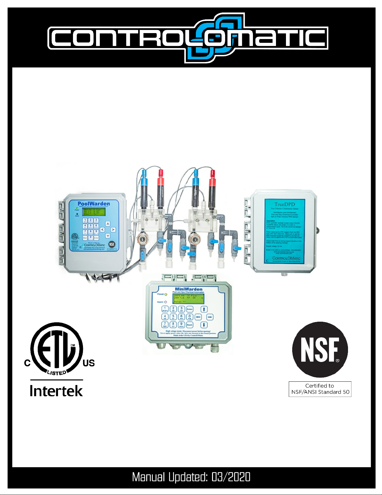
MiniWarden/PoolWarden + (PLUS) Operation Manual • www.poolwardentraining.com • 6
, with over 25 years of technological leadership in Pool & Spa Chemical Control Systems,
congratulates you on your chemical controller selection. PoolWarden measures pH, sanitizer
and temperature on up to two bodies of water (MiniWarden one body of water) and will control the appropriate feed
equipment to keep the measurements within a preprogrammed range. Using ORP (oxidation reduction potential)
technology the control of sanitizer takes into account the effects of pH, and a pH lockout feature is also included for
high pH values. Supporting both 110 and 240 VAC to control chemical feed equipment using relays to keep the pool
or spa water in balance. Water measurements are taken continuously while internal relay programing determines if
chemical adjustments are needed. PoolWarden also contains additional dry-contact auxiliary relays that can be used
to control heaters, pumps, chlorine backup and external alarm notifications. The MiniWarden has the above features
except it is for one pool only and does not have auxiliary relays. The sanitizer relay on the MiniWarden can be
switched between VAC and dry contact.
System Components
tPlus CONTROLLER: Micro computer running the Linux operating system.
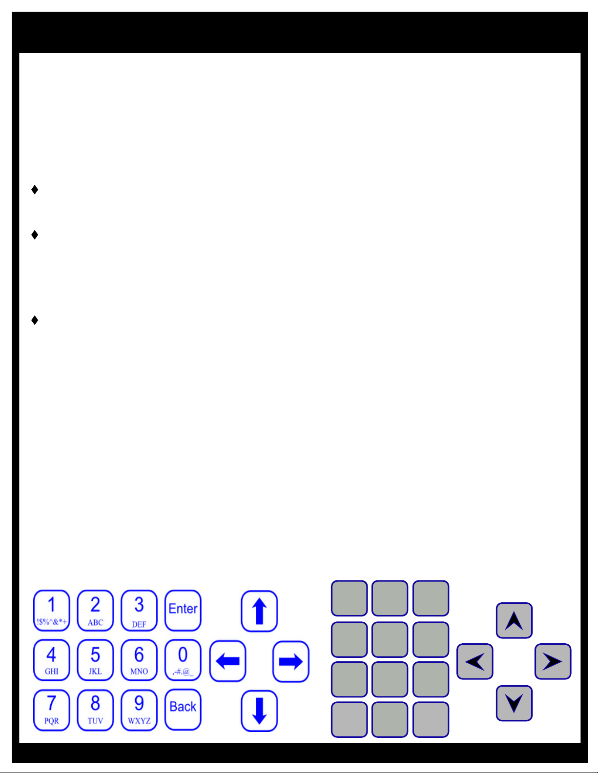
tINTERFACE: A 16-button built in keypad, and an easy to read 80 character liquid crystal display. The display’s
internal back-light provides controller viewing in pool rooms with low light conditions.
tMEMORY: Hard drive is 16 GB MicroSD which preserves all internal programming in case of power loss.
tRELAYS: PoolWarden S (single pool) includes 4 relays (2 of which are dry contact relays). PoolWarden
D (two pools) includes 8 relays. Four of the 8 relays are dry contact relays (2 for each body of water). MiniWarden
includes 2 relays - 1 for pH and 1 for ORP.
tSENSORS: ORP, pH, Temperature, flow and optional free chlorine.
tSECURITY: A lockable enclosure and three levels of password security protection (Admin, Service and Guest)
for both local onsite and remote offsite interaction with the controller.
tCOMMUNICATION: Connection to the Internet for direct monitoring, setup, and data interface via
WIFI and Ethernet.
tDATA: Unlimited data recording.
tHEATERS: Auxiliary relays can control pool heaters with up to two set-points for each day to facilitate
energy management (PoolWarden only).
tPUMP CONTROL: Auxiliary relays can be setup as a simple timer for controlling the on/off state of main pumps
(PoolWarden only).
tOVERFEED PROTECTION: PoolWarden is designed with 2 types of overfeed protection. Standard overfeed
limits the amount of time a relay can turn on feed equipment in a 24-Hour period.
tSPAN CONTROL: Proportionally reduces the on-time as the measurement gets closer to the set-point to prevent
overshoot.
PoolWarden and MiniWarden Plus Versions
This operation manual covers both PoolWarden and MiniWarden and they will both be referred to as PoolWarden.
The MiniWarden/PoolWarden plus version use the same software and share many of the same features. Any
differences will be indicated with (PoolWarden only).
PoolWarden Dual: Sensors and relays will display with a “1” or “2” indicating pool 1 or pool 2. Examples are ORP1,
PPM2, Alarm1, …
PoolWarden Single and MiniWarden: Sensors and relays will display without a number because there is only one
pool.
Plus Conversion: To make a MiniWarden/PoolWarden a Plus install the PW-Plus communication module and in the
Handy Menu enter the code 1927192766. You will need to update all settings. To remove the Plus simply remove the
communication module and follow the on screen instructions.
PoolWarden/MiniWarden Overview

MiniWarden/PoolWarden + (PLUS) Operation Manual • www.poolwardentraining.com • 7
Maximum Electrical Specifications
ITEM DESCRIPTION LIMIT
Input Voltage Maximum input AC voltage 240 VAC, 50-60 Hz
Input Current Maximum input current 10 A
Relay Voltage Maximum relay voltage 240 VAC
Relay Current Maximum Relay Current 2.5 A
Standby Current Maximum operating current 0.1 A Max
Fuse Rating F1 5A, 250V, 05x20
Fuse Rating F2 5A, 250V, 05x20
Fuse Rating F3 1A, 250V, 05x20
pH Measurement of pH 4.22 to 9.98
ORP Oxidation Reduction Potential 0 to 999 mV
Free Chlorine - PPM
With optional TrueDPD sensor NSF Certified Range
0 to 6.0 PPM 10%
Free Chlorine - PPM Extended non-NSF Certified Range 6.0 to 9.5 PPM 20%
Environmental Specifications
ITEM DESCRIPTION LIMIT
Elevation Not to be used above 2000 m
Temperature Minimum/Maximum Operating Temperature 30/110 °F
Temperature Water temperature measurement. 32 to 122 °F
IP Rating Suitable for Outdoor Use IPX3
Pollution Pollution Degree 2
Certifications
NSF/ANSI 50 - Equipment
for Swimming Pools, Spas,
Hot Tubs and Other
Recreational Water Facilities
http://info.nsf.org/Certified/Pools/Listi
ngs.asp?Company=C0214550&Stan
dard=050&
4010758
Conforms to
UL STD 1563
Certified to CSA STD
C22.2 No. 218.1

MiniWarden/PoolWarden + (PLUS) Operation Manual • www.poolwardentraining.com • 8
ITEM DESCRIPTION
PW–SFC Single pool PoolWarden controller with flow cell and sensors
PW-DFC Dual Pool PoolWarden controller with flow cell and sensors pre mounted on white
back panel
PW-SMTD Single pool PoolWarden controller with flow cell and sensors pre mounted on white
back panel
PW-DMTD Dual Pool PoolWarden controller with flow cell and sensors pre mounted on white
back panel
MW-FC MiniWarden with Flow Cell, ORP, pH, Temp sensors and Flow switch
MW-MTD Flow Cell, sensors, 33' of 1/2” flow tubing, 4x Jaco fittings, mounted on 24”x12”
panel
PW-Plus Add the communication option to make the PoolWarden/MiniWarden a Plus.
TrueDPD Adds free chlorine measurement using the DPD colorimetric method. This is
available as a single and dual sensor.
Models and Options

MiniWarden/PoolWarden + (PLUS) Operation Manual • www.poolwardentraining.com • 9
The uses an advanced communication module that controls the operation of the system. An
Internet connection is required for time, date and data functions. A Linux based operating system provides
significant functionality advances including the ability to connect a computer monitor, keyboard and
mouse.
Features
t64bit ARMv7 Quad Core Processor
t1GB Ram
tBuilt in WiFi, Ethernet and Bluetooth
t4 x USB 2 ports
tFull size HDMI for external monitor,
1920x1200
tCSI camera port
tMicro SD port for a hard drive, 8GB
tInternet connection required for time, date and
data. There is no setting for time, date and
daylight savings - it is automatic from the
Internet.
tEasy software updating
tBuilt in web browser, with external monitor
tUnlimited data recording
tData saved in SQLite3 database, easy to retrieve
tBuilt in data server for direct connect
tSupports both mixing time or cycle time relay control
tPH and ORP Control span simplifies proportional
control
tDaily data reporting
tRemoval of the PW-Plus module causes the
PoolWarden/MiniWarden to revert back to the WS
version without communication
PoolWarden / MiniWarden Plus Features

MiniWarden/PoolWarden + (PLUS) Operation Manual • www.poolwardentraining.com • 10
Keyboard
This section reviews all the navigation features associated with keyboard.
tBack: From the main readings display the Back button provides access to the main menu where all
of the configurations are. If password protected then you will need to enter the password to access the
main menu. The Back button will also go back one menu from almost any menu and pressing it
enough times will get back to the readings display.
tEnter: The Enter button provides access to most menus and sub menus and allows you to accept or
save an entry.
Numbers: The number keys allow entry of numbers only. If there is a ‘.’ Or ‘:’ in the number the cursor
may skip over it to highlight the next number. When entering a number, the cursor will skip to the next
number automatically.
Characters (Text): Some values require text entry and the alphanumeric values are shown on each
button as capital letters. The cursor does not skip to the next letter, press the right and left arrow to
position the cursor. Press the same button consecutively to cycle through all the letters and number.
The ordering is the number, then lower case, then upper case and then back to the number. The
current selections that use text include: Name, Pool1 and Pool2 in the Setup menu, SSID and
Password in the Internet WIFI menu, and the AUX relays for the PoolWarden only.
Arrow Keys: The arrow buttons (Up, Down, Left & Right), allow navigation within each menu. All
menus are fully rotational which means if you use the Up arrow to scroll to the top of a menu and
press it one more time - you will be at the bottom of that same menu and vise-versa.
qUp Arrow: Moves the cursor up one selection in a menu.
qDown Arrow: Moves the cursor Down one selection in a menu. Also used to cancel changing a
value.
qLeft Arrow: Moves back to the previous menu just like the Back button.
qRight Arrow: Selects the item the cursor is currently on just like the Enter button.
Entering Values
To change values press the Enter key and edit the value using the keyboard. Press Enter to save the
new setting or Back to abort the change. Some changes cycle through the values, continue to press
Enter or Right Arrow to cycle to the desired setting.
When making changes they will be saved to memory when the controller’s back light turns off which is 2
minutes from the last button press. Press the 5 button on the readings screen to immediately turn the
back light off and save the changes.
Back
1
0
.’()*+,;=: Enter
9
@-_~!$
8
WXYZ
7
TUV
4
JKL
5
MNO
6
PQRS
3
GHI
2
DEF
1
ABC
PoolWarden Keyboard
MiniWarden Keyboard
Operation

MiniWarden/PoolWarden + (PLUS) Operation Manual • www.poolwardentraining.com • 11
Default Readings Screen
The Default Readings Screen is displayed after power up and when a
button isn’t pressed for 2 minutes. It is the most critical screen as it will
display the current pH & ORP sensor readings, flow status, relay status,
alarm status and various symbols that are defined below. Menus within
PoolWarden are accessed through the Default Readings Screen. Please
review definitions of all Row & Column information and symbols below.
Row 1 (Column Header): The first row is a column header and
defines what you find below that particular column header. Example:
The “pH” Column Header on the first row means that the current pH
readings for Pool 1 (7.7) and Pool 2 (7.5) are just below.
Row 2 (Current Measurements Pool1): The current real time
measurements and status for Pool 1. Example for Pool 1: ORP=681,
pH=7.7, Temperature (Tf) = 75 degrees Fahrenheit, Flow switch 1 is
ON. The “a” on the far right indicates that Pool1 is in alarm.
Row 3 (Current Measurements Pool2, PoolWarden only): The current real time measurements and
status for Pool 2. Example for Pool 2: PPM = 3.2, ORP = 695, pH = 7.5, Temperature (Tf) = 102
degrees Fahrenheit, Flow switch 3 is ON and the alarm is not on for Pool2.
Row 4 (Relay Status): Row 4 displays the current status of all the relays in the following order with
symbols that are defined below (RlyP1 = Pool1 and P2 = Pool 2);
qPoolWarden Dual: RlyP1: ORP1, pH1, Aux1, Aux2 P2: ORP2, pH2, Aux3, Aux4
qPoolWarden Single: RELAY: ORP1, pH1, Aux1, Aux2
qMiniWarden: RELAY: ORP1, pH1
q_ : An underline indicates the relay is OFF and not in an active feed cycle. If there is no underline
for the Aux relay then the relay isn’t setup for control.
q↑ : An Up arrow indicates the relay is ON and in an active feed cycle.
q↓ : A Down arrow indicates the relay is OFF and in the OFF part of an active cycle.
qo : An "o" indicates the relay has reached the on time limit (overfeed limit) for the
day and will not turn on again until the overfeed limit clears automatically each night at midnight.
Note that cycling the power doesn’t clear the overfeed time. Select Clear Overfeed Times in the
service menu to reset the timer.
s : An "s" indicates the relay has reached the setpoint overfeed limit and will not turn on again until
the setpoint is achieved by other means (manually adding the required chemicals). Select Clear
Overfeed Times in the service menu to reset the timer.
qThe letter ‘b’ next to an ORP reading indicates ORP is in pH lockout and the feature of feeding
sanitizer at a fixed rate of minutes per hour is on (not available with TrueDPD or MiniWarden).
qThe letter ‘p’ next to an ORP reading indicates ORP is in pH lockout and is off.
q
When the PoolWarden is turned on a time number will display on this line to the right which is a delay
before the relays will operate, the turn on delay gives time for accurate readings prior to controlling the
relays.
Other Symbols Defined:
qThe letter “a” on the right will display when the Pool alarm is on.
tFlow Status: The flow will either be ON or OFF with the standard flow sensor. Flow status for Pool 1
uses Flow 1 input for the sensor connection and Pool 2 uses Flow 3 input for the sensor connection on
the sensor circuit board. This cannot be changed.
qPool1: 1:2, Both flow switch 1 and 2 are on. 1:_, Flow switch 1 is on, 2 is off.
qMiniWarden with TrueDPD: 1:d, Flow switch 1 is on and 2 is used for TrueDPD commands.
qPool2 with TrueDPD: 3:d, Flow switch 3 is on and 4 is used for TrueDPD commands.
tPPM Display on Error: When the TrueDPD has an error the PPM is set to a high value so that it will
not start a sanitizer feed cycle. If that happens the PPM value will display as “—”.
PPM ORP pH Tf Flow
1.5 681 7.7 75 1:_a
3.2 695 7.5 102 3:d
RlyP1↑↓o P2_↓o 23%
PoolWarden+ Dual TrueDDPD
m
v
ORP pH Tf Flow
681 7.7 75 _:_a
RELAY↑↓o 23%
PoolWarden+ Single
m
v

MiniWarden/PoolWarden + (PLUS) Operation Manual • www.poolwardentraining.com • 12
PoolWarden/MiniWarden Menu Structure
Simply press the Back button from the Readings Screen to gain access to the “Main Menu”. From the
“Main Menu” use the Up & Down arrow keys to navigate to each sub menu item and press Enter to go to
that sub menu or selection. Accessing the Main Menu can be password protected and the available
selections will be dependent on the security level of the password.
Menus
Readings Screen
ORP pH Tf Flow
681 7.7 75 1:_a
695 7.5 102 2:_a
RlyP1↑↓o_ P2_↓o_
Internet
Data Server Setup
Information
WIFI Connect
Software Update
Security
Master 0
Operator 0
Service 1 0
Service 2 0
Langelier and Ryzner
Enter measurements in
the Handy menu to
enable the index
Indexes
Press
Up Key
UP
Service
Relay Manual Mode
Clear Overfeed Times
Disable All Relays
Calibration Poo1
TrueDPD
Manual Control
Reagent: Powder
DPD Bottle: 4 oz
Pool1 Cycle:00:30:00
Pool2 Cycle:01:00:00
From Dusk Hour 0PM
Night Time Setpoints
ORP1 0 Orp2 0
to Dawn Hour 0AM
CYA
Service Internet
TrueDPD Security
Relays Printer
CYA Setup
Main Menu
Press
Back Key
Back
m
v
Handy Menu
Daily Noon Data
Past Data
Enter Measurements
Relay Information
About Screen
Enter a Code
Startup Screen
Press
Down Key
Down
Pool 1 Active Alarms
On if PPM < 1.0
Alarm Screen
Press
Right Key
Right
TrueDPD Readings Screen
PPM ORP pH Tf Flow
1.5 681 7.7 75 1:_a
2.5 781 7.3 104 2:da
RlyP1↑↓o_ P2_↓o_ 55%
m
v
PoolWarden+ Pool/Spa
Chemical Automation
SN:790860 04/30/18
05/01/18 11:15:58
Startup Screen
Right
For alarms
on Pool 2
Relays
Ph1 ORP1 AUX1
AUX2 Alarm1
Ph2 ORP2 AUX3
AUX4 Alarm2
Printer
Print Interval 4 hrs
Print Data Now
Print Last 7 Days
Printer MAC Address
00:11:22:33:44:55
Remove Printer
Print Setup
Setup
Units: English
Pools: 2 (Dual)
Names Menu
Aux1: Not Used
Aux2: Not Used
Aux3: Not Used
Aux4: Not Used
Factory Defaults
PH/ORP Ctrl: Mixing
TrueDPD: Enabled
Time Zone - Pacific
Unused Rly Cmds:Show
Alarm Deltas: On
P1 pH LKout min/hr 0
P2 pH LKout min/hr 0
2: ORP Quick Menu
3: pH Quick Menu

MiniWarden/PoolWarden + (PLUS) Operation Manual • www.poolwardentraining.com • 13
Information Menus
PoolWarden has 6 information screens (handy, alarm, Langelier index, setpoint, special information and
TrueDPD) which are all accessible directly from the Readings Screen. The information screens are NOT
password protected.
Handy Menu
Press ▼ Down Arrow or Enter from the default readings screen.
qDaily Noon Data: Allows scrolling through the noon time readings beginning with the last
recording. The right and left arrow change the days. If the controller isn’t on at noon there will be no
reading saved.
qPast Data: This menu provides access to PoolWarden’s internally recorded data. The data can be
displayed visually on screen.
qBack - > Quit: Exit the Data and bring you back to the Data Recording screen.
q↑: Pressing the Up Arrow will jump forward 20 rows of data.
q>: Pressing the Right Arrow will move forward 1 data row at a time.
q<: Pressing the Left Arrow will move backward 1 data row at a time.
↓: Pressing the Down Arrow will jump backward 20 rows of data.
Relay Name pH v
OnToday 00:32:56
MonthOn 0000:32
Cnt 99 TMR 00:04:13
Relay Information
qEnter Measurements: The following manually taken pool
measurements: PPM, pH, ALK, Hardness and CYA can be entered
here. If PoolWarden is communication enabled then the data will be
sent / stored at www.PoolWarden.com with time stamps of when the
measurements were made.
qRelay Information: Displays current information about the relays. When a relay should be on and
isn’t turning on this screen helps to diagnose why the relay isn’t turning on.
qLine 1: Includes the name of the relay and the current status: “v” is in the off part of an active
cycle, “^” is in the on part of an active cycle, “_” not in an active cycle - relay is off. Press the
right and left arrows to switch relays.
Version 1.95
Updated On: 04/20/18
Serial Number 790860
05/02/18 11:51:42
On Cycles: 203
On Time: 157:02
Packets Sent: 284
Data Records: 1066
About Screen
qOnToday: The length of time the relay has been on today. This
can be cleared in the Service menu.
qMonthOn: The total hours and minutes the relay has been on for
the month.
qCnt: The time the relay has turned on in the day.
qTMR: The current cycle timer. If the relay should be on the timer
is typically counting, if not counting then refer to the relay setup
to see why it isn’t turning on.
qAbout Screen: List the total hours the unit has been on, total
number of power up cycles, data packets sent and other
information.
qEnter a Code: Allows for the entry of a factory code that can clear
the passwords or put the controller in a demonstration mode.
qStartup Screen:
qLine 1: Model - PoolWarden or MiniWarden
qLine 2: Name of the location if entered
qLine 3: The serial number and software date
qLine 4: Current date and time are displayed
PoolWarden+ Pool/Spa
Downtown Pool
SN:790860 04/30/18
05/02/18 12:00:15
Startup Screen

MiniWarden/PoolWarden + (PLUS) Operation Manual • www.poolwardentraining.com • 14
Alarm Screen
Press ► Right Arrow from the readings screen to access the alarm menu. The alarm screen shows all the
conditions that are or will cause the alarm light to be on. If the alarm light is off and there are conditions
listed in the alarm screen then the alarm delay hasn’t been reached yet. The alarm delay requires the alarm
on condition to exist for a period of time before the alarm actually turns on.
Alarm conditions are set up in the Relay Setup Menu.
For the PoolWarden dual pool controller, press the Right Arrow a second time for the alarm conditions on
pool 2.
Setpoints
Press the 9 key from the readings screen to show current set-points.
Special Information
If there is anything to report there will be a “4” in the lower right corner of the readings screen. Press the 4
button to see the information.
tWIFI IP address will always be listed.
tIf the ORP is being reduced from the cyanuric acid that will display
tIf unable to connect to the Internet.
Langelier Index
Enter measurements
In the Handy menu
To enable the index
Langelier / Ryzner
Langelier / Ryzner Index
To enable, enter the Alkalinity and hardness in the Handy Menu, Enter
Measurements. To view the index, press the Up Arrow from the readings
screen. If either the Alkalinity or hardness are 0 the index will not display.
Press the up arrow again to cycle between indexes.
TrueDPD Information - Option
Press “6” for the TrueDPD information screen. Appendix F covers TrueDPD.
Quick Menus
Quick access to the most common settings for pH and ORP control. This is also password protected and
for the service password these limited settings can be changed.
tPress “2” from the readings screen for the Quick ORP Menu
tPress “3” from the readings screen for the Quick pH Menu
ORP1 Quick Settings
Acid Setpoint 7.5
MaxTime On 00:00:30
MinTimeOff 00:05:00
ORP1 Quick Settings
Acid Setpoint 7.5
MaxTime On 00:00:30
MinTimeOff 00:05:00
Press “3”
pH Relay Settings
ORP1 Quick Settings
ORP Setpoint 700
PPM Setpoint 2.0
MaxTime On 00:01:00
MinTimeOff 00:05:00
ORP2 Quick Settings
ORP Setpoint 700
PPM Setpoint 2.0
MaxTime On 00:01:00
MinTimeOff 00:05:00
Press “2”
Quick ORP with PPM

MiniWarden/PoolWarden + (PLUS) Operation Manual • www.poolwardentraining.com • 15
Main Menu
The main menu is password protected and where all the configurations take
place. Press the Back button from the readings screen. If security is enabled
a password will be required.
Main Menu - Service
The Service Menu includes common items to service a pool including
manually feeding chemicals and calibration.
tRelay Manual Mode: Use the up and down arrow keys to scroll next to
the relay that needs to be put into manual mode. Press the Enter button
or the Right Arrow to put the selected relay into manual mode.
qIf the relay is currently ON, it will turn off for the manual time and then
go back into auto control.
qIf the relay is OFF, it will turn ON for the manual time and return to
auto control.
If the relay is OFF and in manual mode, it will return to auto.
tClear Overfeed Times: If an overfeed timer has been reached it will only
clear/reset at midnight. There are times when servicing a pool that you
may want to clear the overfeed timers to stop an alarm from tripping or to
have the relay turn back on. This selection also clears the number of
times the relay has turned on during the day and the setpoint overfeed
timer.
Service Internet
TrueDPD Security
Relays Printer
CYA Setup
Main Menu
PH1 00:00:00 OFF
ORP1 00:00:00 OFF
Aux1 not used
Aux2 not used
PH2 00:00:00 Off
ORP2 00:00:00 Off
Aux3 not used
Aux4 not used
Relay Manual Mode
Cal ORP1 650 -16%
Cal pH1 7.7 -5%
Cal Temp1 78 +12%
Clear Cal ORP1
Clear Cal pH1
Clear Cal Temp1
Cal PPM1 3.4 -6%
Clear Cal PPM1
Calibration
qCycling power does not clear the overfeed timers.
The Setpoint Overfeed timers are also cleared when selecting the Clear Overfeed Times.
Relay Manual Mode
Clear Overfeed Times
Disable All Relays
Calibration Pool1
Calibration Pool2
Service Menu
Disable All Relays: Press Enter or Right Arrow to increment the hours off from 0 to 13. When the
relays are disabled, the readings screen bottom row will display “RLY Off 03:30:53” showing how much
longer until the relays go back to automatic control.
tCalibration Pool1 and Pool2: Select the desired pool to calibrate and
scroll to the sensor to calibrate. Manual Pool Measurements must be
taken to calibrate each sensor. For best results the pool should be at the
setpoints when calibrating. The percentage to the right of the current
reading is the amount of calibration and if it is at 99% that sensor is at the
maximum calibration and may need to be replaced. When calibrating,
press Back or Down Arrow to cancel and Enter to save the new
calibration. The current value displayed in the calibration screens is the
un-calibrated sensor.
qpH: Enter the manually measured pH value. A pH sensor can be
calibrated +/- 2 pH units.
qORP: If the sanitizer level is higher than desired and the pH is at the
setpoint then raise the ORP calibration slightly. If the sanitizer level is
lower than desired and the pH is at the setpoint then lower the ORP
calibration slightly. The ORP sensor can be calibrated +/- 200 mV.
ORP sensors are affected by cyanuric acid, pH and other factors and it
may take a few days to get it adjusted.
Calibrate pH1
Current: 7.7
Range 4.2 to 9.8
v-Cancel
Calibrate pH
qTemperature: Enter the manually measured temperature. A temperature sensor can be calibrated
+/- 25 degrees Fahrenheit. If the sensor need a lot of calibration it may need to be relocated closer
to the water inlet from the pool.
qPPM: If the TrueDPD is connected there will be a selection for calibrating the free chlorine. Refer to
appendix F for more information.
qClear Cal: Removes the calibration and the reading is immediately updated.

MiniWarden/PoolWarden + (PLUS) Operation Manual • www.poolwardentraining.com • 16
Main Menu - TrueDPD
See appendix F.
Main Menu - Relays
The PoolWarden Aux relays are covered in the Setup section and Appendix A.
From the Readings Screen press the Back button to access the Main Menu
and select Relays. The relays are controlled with commands that can be
enabled or disabled. Any command that has a value of 0 is disabled. The
values listed are the defaults. When using the Cycle control type, please refer
to appendix B. Only Aux relays that have been setup will display. Scroll to the
appropriate relay and press Enter to edit the settings.
Relay Setup: pH1 and pH2
In the Relay Menu scroll to pH1 or pH2 and press Enter. The following
reviews each command within a pH Relay.
tManual Time 00:02:00: Is the amount of time you can set a relay to turn
on manually.
tPH Control Span: Select 0.0, 0.2, 0.3 or 0.4. When the measurement is
greater than the span away from the setpoint the on time will be the full on
time. When the measurement is between the setpoint and the span away
from the setpoint the on time will be decreased to reduce overshooting the
setpoint. When set to 0.0 the on time will not be adjusted. Press Enter or
Right Arrow to cycle the values.
pH1 ORP1
Alarm1
pH2 ORP2 ORP
Level Alarm2
Relay Setup Menu
ManualTime 00:02:00
pH Control Span 0.3
Acid Setpoint 7.5
Base Setpoint 0.0
On DELAY 00:00:20
MaxTime On 00:00:30
MinTimeOff 00:05:00
Off if RLY On none
Off if Flow Off FS 1
SetOvrfeed 00:00:00
Overfeed 01:00:00
pH Relay Settings
tAcid Setpoint 7.5: The relay will turn on if the measured pH reading is greater than 7.5.
tBase Setpoint 0.0: The factory default setting is 0.0 (disabled). When set, the relay will turn on if the
measured pH reading is less than the value. Note: One of the two setpoints must be 0.0.
tOn Delay 00:00:20: The turn on delay requires the setpoint condition to be met for an extended period
of time before turning the relay on. The value 00:00:00 disables the on delay.
tMax Time On 00:00:30: When the relay turns on this is the maximum time before it turns off. If the pH
reading is not being maintained then more or less on time may be needed. The maximum time may be
less if the pH control span is used.
tMinTimeOff 00:05:00: This is the minimum amount of time the relay will be OFF after it was on. Allows
for chemical mixing.
tOff If RLY On -none: The default setting is none or disabled. This feature prevents 2 relays being on at
the same time. This is useful in cases where the chemical injection points are very close together and
prevents the pH relay from being on at the same time the ORP relay is on. Simply press Enter to toggle.
tOff if Flow Off - 1 or 3: The pH Relay will be turned off if “No Flow” is detected in Flow Switch Input 1
for Pool1 and if “No Flow” is detected in Flow Switch Input 3 for Pool2. Note: This setting can’t be
changed as it relates to safety, pressing the Right Arrow to change has no effect.
tSetOvrfeed 00:00:00: Setpoint overfeed requires the measurement to reach the setpoint to clear. If a
feed tube is broken and the chemicals are going on the floor this type of overfeed protection will detect
that and shut down the relay sooner than the daily overfeed. Calculate how much feed time is required
for the setpoint to be reached when the pH is a full point off. When the Setpoint Overfeed is reached the
relay status will display an “s”. The default value is 00:00:00 which is disabled, in order to use this feature
calculate the amount of time required and enter that time.
qSetpoint Overfeed can be cleared by manually fixing the chemical imbalance or clearing the overfeed
timers in the Service menu.
tOverfeed 01:00:00: The Overfeed time represents the maximum amount of time a relay can be on from
midnight to midnight. This must be set up properly to reduce the chance of feeding large amounts of
chemicals in the event something goes wrong and the default time will most likely need to be adjusted.

MiniWarden/PoolWarden + (PLUS) Operation Manual • www.poolwardentraining.com • 17
1. Calculate the total amount of chemical the pool would ever need in a 24 hour period.
2. Calculate the amount of time it would take the feed-pump to inject that total amount of chemical in
a 24 hours. Example: Limit to 1 gallon with a 10 Gallon Per Day (GPD) Fixed Rate Peristaltic
Pump. 1 Gallons / 10 Gallons * 24 Hours = 2.4 hours or 02:24:00. You will need to adjust for
variable pumps depending on the variable pump setting. Most variable pumps use a scale of 10 to
0. So if the pump is set on 8 then use 80% of the total GDP rate, in this case .80 x 10 GPD = 8
GPD.
3. Calculate the overfeed time with the following equation using the following example…..
Overfeed Time = (Daily Gallon Limit) / (Pump GPD Rate) times (24 Hours)
ManualTime 00:02:00
ORP Control Span 40
PPM Control Span 1.0
ORP Setpoint 700
PH Lockout 0.0
PPM Setpoint 2.0
On DELAY 00:00:20
MaxTime On 00:01:00
MinTime On 00:00:00
MinTimeOff 00:05:00
PPM High Limit 0.0
ORP High Limit 0
Off if Flow Off FS 1
SetOvrfeed 00:00:00
Overfeed 01:00:00
with TrueDPD PPM
ORP1 and ORP2 Relay Configuration
In the Relay Setup Menu scroll to ORP1 or ORP2 and press enter. If the
TrueDPD is enabled there will be PPM commands.
tManual Time 00:02:00: Is the amount of time you can set a relay to turn
on manually.
tORP Control Span: Press Enter to cycle between 0, 10, 20, 30, 40 and 50
mv. If the measurement is less than the span below the setpoint then the
relay will be on for the full on time and if in between the setpoint and the
span the on time will be proportionately decreased. If the measurement is
greater than the setpoint the relay will be off. Span control helps to prevent
chemical overshoot.
tPPM Control Span: Press Enter to cycle between 0, 0.5, 1.0, 1.5 and 2.0
ppm. If the measurement is less than the span below the setpoint then the
relay will be on for the full on time and if in between the setpoint and the
span the on time will be proportionately decreased. If the measurement is
greater than the setpoint the relay will be off. Span control helps to prevent
chemical overshoot. If both PPM and ORP spans are used, the higher
calculated on time will be used.
tORP Setpoint 700: The relay will turn on if the ORP is less than 700.
tpH Lockout 0.0: The pH Lockout default setting is zero “0” or disabled.
ORP is highly dependant on pH. A high pH reduces the effectiveness of
the sanitizer and has a direct effect on lowering the ORP even though
there may be an ample amount of sanitizer in the water. pH Lockout helps
to prevent chlorine overfeed. A typical pH Lockout setting is 8.0 and will
lockout (keep from turning on) the ORP relay when pH reaches 8.0 or
higher. This command doesn’t effect the PPM setpoint. In the setup menu
a feed time in minutes per hour can be selected to allow some feeding of
sanitizer during pH lockout, this feature is only available if the TrueDPD
isn’t enabled.
tPPM Setpoint 2.0: The relay will turn on if the measured PPM is less than
2.0. As a Safety the PPM must also not be 0.0. If the DPD reagent is out
or something is wrong with the TrueDPD it may measure 0.0.
ManualTime 00:02:00
ORP Control Span 40
ORP Setpoint 700
PH Lockout 0.0
On DELAY 00:00:20
MaxTime On 00:01:00
MinTime On 00:00:00
MinTimeOff 00:05:00
ORP High Limit 0
Off if Flow Off FS 1
SetOvrfeed 00:00:00
Overfeed 01:00:00
ORP Settings
tOn Delay 00:00:20: The turn on delay requires the setpoint condition to be met for an extended period
of time before turning the relay on. The value 00:00:00 disables the on delay.
tMax Time On 00:01:00: When the relay turns on this is the maximum time before it turns off. If the
sanitizer level is not being maintained then more or less on time may be needed. The maximum time
may be less if the sanitizer span is used. Use Max Time On for liquid sanitizer.
tMin Time On 00:00:00: This is the minimum amount of time the relay will be ON if the measurement is
below the setpoint. Use this command for salt water chlorine generators and chlorinators. With this type
of on time, when the relay turns on it will be on until the setpoint is reached and for at least the on time
specified. Span isn’t used. Note: Max Time On and Min Time On can’t both be 00:00:00 and one is
required to be 00:00:00.

MiniWarden/PoolWarden + (PLUS) Operation Manual • www.poolwardentraining.com • 18
tMinTimeOff 00:05:00: This is the total amount the relay will be OFF in the off part of the cycle and is
part of the mixing time. This command can’t be disabled.
tPPM High Limit 0.0: Prevents feeding sanitizer if the PPM reading reaches a high value.
tORP High Limit 0: Prevents feeding sanitizer if the ORP reading reaches a high value.
tOff if Flow Off - 1 or 3: The ORP Relay will be turned off if “No Flow” is detected in Flow Switch Input
1 for Pool1 and if “No Flow” is detected in Flow Switch Input 3 for Pool2. Note: This setting can’t be
changed.
tSetOvrfeed 00:00:00: Setpoint overfeed requires the measurement to reach the setpoint to clear. If a
feed tube is broken and the chemicals are going on the floor this type of overfeed protection will detect
that and shut down the relay sooner than the daily overfeed. Calculate how much feed time is required
for the setpoint to be reached starting from 0. When the Setpoint Overfeed is reached the relay status
will display an “s”. The default value is 00:00:00 which is disabled, in order to use this feature calculate
the amount of time required and enter that time.
qSetpoint Overfeed can be cleared by manually fixing the chemical imbalance or clearing the
overfeed timers in the Service menu.
tOverfeed 01:00:00: The Overfeed time represents the maximum amount of time a chemical relay will
feed in a day from midnight to midnight. This must be set up properly to reduce the chance of feeding
large amounts of chemicals in the event something goes wrong. The default time will most likely not be
correct. Please follow the calculation below. The minimum value for Overfeed time is 1 minute, it can’t
be disabled.
qCalculate the total amount of chemical the pool would ever need in a 24 hour period. (Example: 10
Gallons would be the MOST liquid chlorine a pool would need on any given day).
qCalculate the amount of time it would take the feed-pump to inject that total amount of liquid chlorine
in a 24 hour period. Example: Limit to 10 gallons with a 50 Gallon Per Day (GPD) Fixed Rate
Peristaltic Pump. 10 Gallons / 50 Gallons * 24 Hours = 4.8 hours or 04:48:00. You will need to adjust
for variable pumps depending on the variable pump setting. Most variable pumps use a scale of 10
to 0. So if the pump is set on 8 then use 80% of the total GDP rate, in this case .80 x 50 GPD = 40
GPD.
qCalculate the overfeed time with the following equation using the following example…..
Overfeed Time = (Daily Gallon Maximum) / (Pump GPD Rate) times (24 Hours)
Round up and set the overfeed time. It can be set for minutes and seconds for finer control.
Alarm 1 and 2 Setup
The Relay menu includes the alarm settings for the alarm light on the enclosure lid. Scroll to Alarm1 or
Alarm2 and press Enter. To use delta values based on the setpoint rather than absolute values turn on
Alarm Deltas in the Setup menu.
Absolute Sensor Alarms
tHigh Alarms: The alarm will turn on if the sensor is greater than the value.
tLow Alarms: The alarm will turn on if the sensor is less than the value.
Delta Sensor Alarms
Delta alarms are handy if you often change the setpoints. In that case the alarm limits automatically change
without needing to also change the alarm limits. Temperature doesn’t use delta alarms.
tORP+: Setpoint + 100: The alarm will turn on if the sensor is greater than the ORP setpoint + the
value. Press Enter to cycle between 0, 50, 100, 150, 200 and 250.
tORP-: Setpoint - 100: The alarm will turn on if the sensor is less than the ORP setpoint - the value.
Press Enter to cycle between 0, 50, 100, 150, 200 and 250.
tPPM+: Setpoint + 3.0: The alarm will turn on if the sensor is greater than the PPM setpoint + the value.
Press Enter to cycle between 0.0, 0.5, 1.0, 1.5, 2.0, 2.5 and 3.0.

MiniWarden/PoolWarden + (PLUS) Operation Manual • www.poolwardentraining.com • 19
tPPM-: Setpoint - 1.0: The alarm will turn on if the sensor is less than the PPM setpoint - the value.
Press Enter to cycle between 0.0, 0.5, 1.0, 1.5, 2.0, 2.5 and 3.0.
tpH+: Setpoint + 0.4: The alarm will turn on if the sensor is greater than the pH setpoint + the value.
Press Enter to cycle between 0.0, 0.1, 0.2, 0.3, 0.4 and 0.5.
tpH-: Setpoint - 0.4: The alarm will turn on if the sensor is less than the pH setpoint - the value. Press
Enter to cycle between 0.0, 0.1, 0.2, 0.3, 0.4 and 0.5.
Remaining alarm conditions
tOn If Flow Off FS 1: The alarm will turn on if no flow is detected. Pool1 uses Flow Switch Input 1 and
Pool2 uses Flow Switch Input 3. To turn the alarm status on if no flow is detected for Pool1 simply hit
the Enter Key to change the value from “none” to FS 1 (Flow Switch Input 1). To turn the alarm status
on if no flow is detected for Pool2 simply hit the Enter Key 3 times to change the value from “none” to FS
3.
tOn If Overfeed - YES: The alarm will turn on if the daily overfeed or setpoint overfeed has been
reached for the indicated pool including the pH, ORP and Aux relays.
tIf DPD Below 10%: With the TrueDPD enabled, this will turn the alarm on if the DPD reagent bottle
drops below 10%. Make sure to set the value in the TrueDPD information screen.
tIf DPD Error: If there is an error detected by the TrueDPD sensor such as the clear voltage below 3.50
turn the alarm on.
tOff If Flow Off - none: The PoolWarden will not send alarm notification if no flow is detected. If the
main pump is off then you may not want to get alarm notifications.
tOn Delay 00:10:00: The alarm will only turn on if this condition is satisfied for at least 10 Minutes. This
command prevents multiple alarms if the sensor readings are fluctuating back and forth.
tMin Time On 00:00:10: The alarm will be on at least this long giving time for notifications to be sent out.
tMin Time Off 00:00:10: When the alarm turns off, it will be off at least this long.
tOff If Time < 00:00:00: This is a time of day command. Used to disable the alarm in the morning. If not
00:00:00, the alarm will be off from midnight until the time in this command. Use this command if you
don’t want notifications at night.
ORP High Alarm 800
ORP Low Alarm 600
PPM High Alarm 7.0
PPM Low Alarm 1.0
pH High Alarm 8.0
PH Low Alarm 6.0
Temp High Alarm 0
Temp Low Alarm 0
On if Flow Off FS 1
On if Overfeed Yes
Off if Flow off none
If DPD Below 10% Yes
If DPD Error No
On DELAY 00:10:00
MinTime On 00:00:10
MinTimeOff 00:00:10
OffIfTime< 00:00:00
OffIfTime> 00:00:00
with TrueDPD PPM
ORP High Alarm 800
ORP Low Alarm 600
pH High Alarm 8.0
pH Low Alarm 7.0
Temp High Alarm 0
Temp Low Alarm 0
On if Flow Off FS 1
On if Overfeed Yes
Off if Flow off none
On DELAY 00:10:00
MinTime On 00:00:10
MinTimeOff 00:00:10
OffIfTime< 00:00:00
OffIfTime> 00:00:00
Alarm Settings
ORP+: Setpoint + 100
ORP-: Setpoint - 100
PPM+: Setpoint + 3.0
PPM-: Setpoint - 1.0
pH+: Setpoint + 0.4
PH-: Setpoint - 0.4
Temp High Alarm 0
Temp Low Alarm 0
On if Flow Off FS 1
On if Overfeed Yes
Off if Flow off none
If DPD Below 10% Yes
If DPD Error No
On DELAY 00:10:00
MinTime On 00:00:10
MinTimeOff 00:00:10
OffIfTime< 00:00:00
OffIfTime> 00:00:00
with TrueDPD PPM
Absolute Alarms Delta Alarms

MiniWarden/PoolWarden + (PLUS) Operation Manual • www.poolwardentraining.com • 20
Main Menu - Cyanuric Acid - CYA
ORP Is effected by cyanuric acid and during the day the ORP measurement
will drop and at night it will go up for the same chlorine and pH level if there is
cyanuric acid in the water. The higher the concentration the larger the ORP
change. At night the ORP increases and the controller will not feed any more
sanitizer until the sun comes up the next day, but during the night the actual
chlorine may drop so in the morning the chlorine level may be low. Increasing
the ORP setpoint at night will allow for sanitizer to still be fed even in the
presence of cyanuric acid.
tfrom Dusk Hour 0 PM: Use the CYA ORP setpoint from this hour at
night. Select from 0, 5, 6, 7, 8, 9, and 10 PM. Set to 0 to not adjust until
after midnight.
tORP1: Enter the ORP setpoint for pool 1.
tORP2: Enter the ORP setpoint for pool 2.
From Dusk Hour 0PM
Night time Setpoints
ORP 0
to Dawn Hour 0AM
CYA - Single Pool
From Dusk Hour 0PM
Night time Setpoints
ORP1 0 Orp2 0
to Dawn Hour 0AM
CYA - Dual Pools
tto Dawn Hour 0 AM: Continue in the morning until this hour. Select from 0, 5, 6, 7, 8, 9, and 10 AM.
Set to 0 to only adjust before midnight and not the morning.
In order to set this value observe the ORP reading at noon and midnight with the same sanitizer level, if
the cyanuric acid had no impact the ORP values would be the same.
When the ORP is being reduced, the status will be indicated in the info screen, press 4 from the readings
screen. If the hour matches the ORP will be reduced, if set to 10 AM, the ORP will be reduced until
10:59:59 AM.
Data Server Setup
Information
WIFI Connect
Software Update
Internet Menu
Main Menu - Internet
The MiniWarden+ and PoolWarden+ include built in WiFi, Ethernet and
Bluetooth. An Internet connection is required for accurate time and date. See
appendix G for connection information.
Data Server Setup
tSend Data Packet: Send data to the server to make sure it is working.
tInterval: The choices are 0 (no data), 15, 30, 60, 120 and 240 minutes.
Note: Data will be sent to the data server at the specified interval in line
with the actual time and stored into the internal database. Data recording is
based on this interval in the Internet setup.
tStart Hour: Enter the hour to start sending data. Use this feature if you
don’t want to send data at night.
Send a Data Packet
Interval 30 min
Start Hour 0
End Hour 0
On Alarm No
Data Server Setup
tEnd Hour: Enter the hour to stop sending data
tOn Alarm: Send a data packet if the alarm turns on
Information
tLan and WiFi MAC address: Some routers use the MAC address to grant access.
tLan and WiFi IP address: The assigned IP address for both are listed.
WIFI Connect
tSSID: Enter the name of the network. Use a smart phone to list the available networks and to verify the
correct spelling. The limit is 20 characters.
tPass: Enter the network password. The limit is 20 characters.
tSecurity: The type of security protocols is in the works.
tUpdate: Performs the following: save the setup, update the WIFI settings and re-start the controller. For
additional information refer to appendix G.
This manual suits for next models
3
Table of contents
Other ControlOMatic Controllers manuals