Cool lights CL-MF0070 User manual

CL-MF0070 70w CDM
(Ceramic Discharge Metalhalide)
Fresnel
Operations Manual
Cool Lights USA
www.CoolLights.biz
Manual V1.0. Cool Lights CL-MF0070 is © Copyright 2009 CoolVideoLights.Com
All Rights Reserved.

2
Table of Contents
INTRODUCTION.............................................................................................................................................................................3
ASSEMBLY PROCESS...................................................................................................................................................................3
REMOVE THE FRESNEL FROM THE BOX...........................................................................................................................................3
INSERT THE BULB IN THE FRESNEL..................................................................................................................................................4
PUT THE FRESNEL ON A STAND .......................................................................................................................................................4
ATTACH THE LAMP HEAD (FRESNEL)TO BALLAST CABLE TO THE BALLAST.................................................................................5
Mounting ballast on the light stand..........................................................................................................................................5
Turn on the ballast.....................................................................................................................................................................5
Angle adjustment using the yoke...............................................................................................................................................6
BARNDOORS ....................................................................................................................................................................................6
FIXTURE TRANSPORT.......................................................................................................................................................................7
TROUBLESHOOTING....................................................................................................................................................................7
OPERATING SPECIFICATIONS AND PARAMETERS.........................................................................................................8
GENERAL SPECIFICATIONS..............................................................................................................................................................8
OPERATING SPECIFICATIONS ..........................................................................................................................................................8
CONCLUSION ..................................................................................................................................................................................8

3
Introduction
This is the operations manual for the Cool Lights USA CL-MF0070 CDM (Ceramic Discharge
Metalhalide) 70 watt Fresnel Spotlight. Your CDM 70 puts out an equivalent hard light to a
tungsten 300w fresnel (without the same wattage draw or heat) and includes all the features
you would expect to find in any fresnel including a focus control and fresnel lens. You should
have received the CL-MF0070 fresnel, a barndoor unit, mounting yoke with yoke to baby stand
adapter, 10 ft. fresnel to ballast connection cable (permanently attached to fresnel on one
end), a70w CDM ballast, 15 foot American power cordwith IEC adapter and a CDM bulb in
5400K (currently there is not a 3000K color temperature option of bulb as on the CDM 150
frensel). While the CDM 70 ballast includes an American power cord, it functions on any
voltage between 100VAC and 240VAC 50/60hz. All items have been protected by the
Expanded Polyethylene (EPE) Foam pictured in Figure 1, which shows the contents of the box
your order number and which part or parts are missing.
Figure 1: Packing of the CL-MF0070 Fresnel
Assembly Process
Remove the fresnel from the box.Take the fresnel from the box and remove the
plastic sac which surrounds it for protection. Also remove the CDM 70 ballast. The fresnel-to-
ballast connection cable (also known in the industry as “ballast-to-lamp head cable”)is
permanently attached to the fresnel and has a 3 pin, keyed bayonet style connector on one
end. This connector will mate with the female side on the CDM 70 ballast and lock in place
with 1/3 turn. You should find the bulbs you were to receive in the same box packed in the
EPE foam inserts. Remove those also—they come in a small cardboard box.

4
Insert the bulb in the fresnel.In order to
insert the CDM bulb into the fresnel, you must open
the top lid to access the socket area inside. While
the insertion of the bulb may be easy, it is not
intuitive how to access the bulb compartment by
opening the lid. This is because the lid has a
seamless look to it and it is not evident that it can
be opened. Starting off, you should hold the lid as
shown in figure 2. This picture shows that the left
side (facing from the back or top) has hinges for
the lid and thus, the other side is a sort of latch and
is the side you will open from. To open
the lid, you should push in on the lid
firmly until it unlatches from the right
side (the side opposite of the hinges).
Then simply open it up. Inside you can
see what is known as the focusing
sled. On the focusing sled is the mirror
and the G12 socket where you will
insert the CDM bulb. Since the bulb
has an outer envelope of quartz, you
should not handle it directly with your
hands. It’s best to use a soft cloth of some sort as
shown in Figure 4. The oils from your fingers can
shorten the life of the bulb so keep this in mind!
There is no polarization on the bulb so therefore it is
not important which pin goes into which part of the
socket. To close the lid, simply shut it, squeeze a
bit on the lid and latch it back in place.
Put the fresnel on a stand.The bottom of the yoke on the
fresnel includes a yoke to baby stand adapter with a thumbscrew
adjustment to lock it in place. Open the thumbscrew enough to
allow the unobstructed insertion on the baby “spud”or 5/8”male
adapter at the top of your stand. Then tighten the thumbscrew to
make sure of a secure attachment. The fresnel should not wobble
on the connection.
Figure 2 –The hinge side of the lid on the
left
Figure 3 –The right side opens…
Figure 5 –Putting the fresnel on
a stand
Figure 4 –Inserting the bulb

5
Warning. You should not over-tighten the thumbscrew either as it can be stripped and ruined
with too much forcing. Just apply enough tightening pressure to get a good connection and
not more.
Attach the lamp head (fresnel) to ballast cable to
the ballast.The lamp head has a 10 foot cable attached
to it with a gray 3 pin connector on the end as shown in
Figure 6. This connector is keyed and cannot be attached
wrongly to the ballast. Simply find the key and match it to
the connector on the ballast and then turn 1/3 turn to lock
and secure it in place.
Warning. You should never attach this connector while the
ballast is plugged in to line voltage, nor should you un-attach
it while ballast is plugged in. You run the risk of damaging
the ballast in this case!
Mounting ballast on the
light stand. The ballast
includes a nylon strap and
carabiner clip (attached to its
back) to allow versatile
attachment in different
configurations to the light stand
or yoke. You can simply attach the carabiner to one of the
thumscrews of the light stand or to the yoke. You can wrap the
nylon strap around the base of the light stand, etc. Many different
configurations are possible with this included type of attachment.
Of course, you can also just lay the ballast on the floor at the base
of the light stand as well. Figure 7 shows the carabiner attached
to the top riser thumbscrew of the light stand.
Plug the ballast into the wall socket. Make sure the power switch of the ballast is in the
off or “0”position. Using the included American IEC type power plug, insert the IEC adapter
end into the ballast and the other plug end into the wall socket. The ballast can operate on any
voltage in the world from 100v to 240v 50/60hz. To adapt
the American power plug to another socket type in another
country is a simple mechanical type adapter and no other
transformer or other type of adaptation is necessary.
Turn on the ballast. Simply turn the ballast switch to
the “1”or on position. The switch is pictured in Figure 6
right next to the IEC power plug.Once started, the light
slowly comes up to full color temperature over 5 minutes
(or less). It starts faint and gradually builds up to a bluish-
green cast and finally to 5400K for the “daylight”CDM.
Figure 6 –The connectors and
switch on the ballast
Figure 7 –Ballast attached to
stand with carabiner
Figure 8 –The bulb takes up to five
minutes to stabilize color
temperature.

6
Figure 9 shows the color stabilization of the light after 5 minutes.
IMPORTANT NOTE ON BULB IGNITION / COOL DOWN:
Should you turn off the fresnel or should the power go out
(unplanned), you should not expect the fresnel to light again for
5 minutes or so. If you do turn it back on before the cool down
period is over, there is an enforcing timer in the ballast that
keeps it from coming on until it senses the bulb has cooled
down enough. It will retry every 2 minutes or so until it senses
the current necessary to ignite is in the proper range (bulb is
cool) and will then reignite. This type of bulb and system is
known as a “cold start”system or “not hot restart”(NHR). An
“HMI”(Osram Trademark) or one of its “clones”is a hot restart type bulb and has a lesser life.
This is one major reason why the CDM 70 bulb life is so long as it is not a hot start (HMI) type
of bulb. This hot restart process is extremely stressful to the bulbs and the main reason that
HMI bulbs do not last much over 750 to 1000 hours.
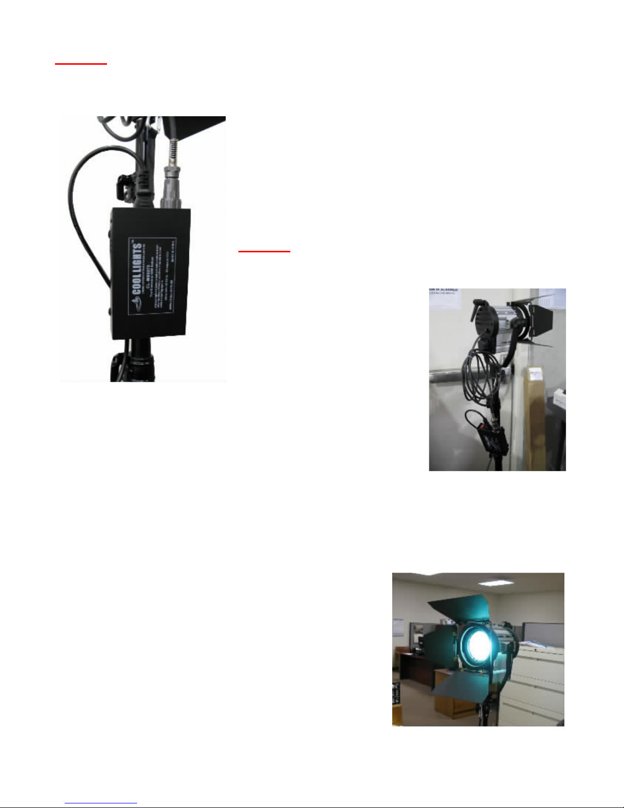
Beam focusing. On the back of the fresnel is a knob
for focusing the spotlight beam between a wide and
narrow beam. The knob simply controls a screw drive
which rolls the focus sled inside the fresnel back and
forth. You will find this to be one of the best features of
a fresnel and also the kind of control you typically won’t
find in a floodlight or other type open face light. The
ability to go between a wide or narrow beam and the
barndoors will allow many different kinds of effects.
Colored gels clipped to the barndoors make the effects
even more interesting. Effects such as a light streak on
the background behind a subject. In figure 10, you can
also see a handle on the back of the unit, this is to allow
easy positioning of angle of the fresnel while it is hot.
Angle adjustment using the yoke. When you need to adjust the
angle of the fresnel, un-tighten the thumbscrew knob on the side of
the fresnel and using the handle (shown in figure 10) on the back of
the fresnel simply move into the position desired and retighten the
thumbscrew as shown in Figure 11.
Barndoors.The CL-MF0070
CDM 70 fresnel includes as
standard a barndoor unit which
fits into the accessory holder on
the front of the fresnel. The
barndoors come attached to the
fresnel out of the box. They are
Figure 12 –Barndoor lock.
Figure 9 –Color Stabilized
after 5 minutes.
Figure 11 –Angle
adjustment thumbscrew.
Figure 10 –The beam focus knob and
handle.

7
locked in place with a safety lock on the top of the fresnel as pictured in Figure 12. In order to
unlock this lock and remove the barndoors, simply pull up on the lock and swing it over to one
side so it no longer attaches to the barndoor. Then just slide the barndoor up and out of the
accessory holders. There is a ring around the barndoor where it attaches to these holders to
allow rotating the barndoors 360 degrees around. This is useful in the light streak effects
mentioned earlier to get an angle on the streak of light on the wall. When closing the
barndoors for storage or shipping, the side flaps close first then the upper and lower fold over
the top of the side flaps.
Fixture transport. When transporting the fixture, its best to take the delicate and fragile
bulb out if there is even the slightest chance of the fixture not being well protected from bumps
and mishaps.
Warning. Wait until the bulb is well cooled down before moving the fresnel around or trying to
take it out of the socket. The bulb can be damaged during transport of the fresnel so wait until
cool and remove the bulb and store in a secure carrying case. Serious burns or injury can
result from touching the hot bulb during its cool-down period!
Troubleshooting
When troubleshooting any problem, always start with the simplest possibilities and work
forward to the more complex ones as you exhaust each scenario. Start with the power plug
and make sure it is not only securely plugged into the wall and the IEC plug adapter. The lamp
head to ballast connector as well should be securely plugged into the CDM 70 ballast. After
that, make sure you have the bulb securely fastened into the G12 socket and are working
within the suggested optimum operating temperatures of 60ºF and 125ºF (15ºC to 51ºC).
There is no fan in the ballast so it is highly recommended not to use it in overly hot conditions
for a long period of time.
If all trouble shooting options are exhausted, then you most likely have developed a bad
switch, ballast or socket. If the unit is still in warranty, you will need to acquire an RMA from

8
Operating Specifications and Parameters
General Specifications
Lens Size: 70mm
Accessory Holder Size: 128mm
Weight:: 4lbs.
Construction: Cast aluminum and aluminum extrusions
Dimensions: 6.5" long X 11" high X 7" wide
Lamp Socket Type: G12
Lamp Type: CDM 70w metal halide type (high CRI)
Ballast Power Requirements: 100v to 240v 50 / 60 hz
Amperage: .75 amps at 110v / 1.5 amps at 220v
Power plug type: American 3 prong (grounded) to IEC adapter
Dimming Capability: No
Operating Specifications
Optimal Temperature Range: 60ºF to 125ºF (15ºC to 51ºC)
Conclusion
This completes setup and testing of the Cool Lights CL-MF0070 CDM 70 Fresnel Spotlight.
With proper care, you should get many years of service out of its sturdy aluminum
construction, high quality sockets and reflectors and superior universal voltage input ballasts.
Thanks for your business!
Cool Lights USA
5360 Capital Court, Suite 100
Reno, NV 89502
www.CoolLights.biz / info@CoolLights.biz
Table of contents
Popular Spotlight manuals by other brands

Light-Point
Light-Point FOCUS MINI 1 instruction manual

Beyond Lighting
Beyond Lighting BY-F600 user manual

Daniamant
Daniamant Dan W3 Installation and maintenance instructions

Vector
Vector 3 Owner's manual & warranty information

Philips
Philips SmartSpot 57966/48/16 user manual

Volt
Volt VAL-2016 installation instructions