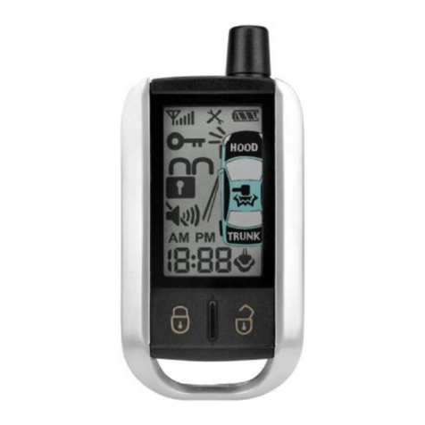
Cool Start RS1-G4 User manual

RS1-G4/ RS3-G4/ RS4-G4
RS7-G4 (PAGINGSYSTEM)
RS00-G4 (ADD-ON MODULE)
REMOTESTART SYSTEM
INSTALLATIONINSTRUCTIONS
CONGRATULATIONS onyourchoiceofa“CoolStart”SystemwithDataPortTechnologyfordirectconnectiontobypass
modulebyCrimestopperSecurityProductsInc.Thisbookletcontainstheinformationnecessaryforinstallingyourremote
starter system.Ifanyquestionsarise,contactyourinstallationdealerorCrimestopperSecurityProductsInc.attheTech
Support number below.
Note:Some features will notbeavailableon unitswith 1button, 3button, and 4button remotes.
DISCLAIMER:
Thisinstallation bookisdesigned for the installer or individualwithan existing understanding ofautomotiveelectrical
systems,along withthe abilitytotestand connectwiresfor proper operation.Toeaseinstallation,wesuggestthatyou
READ THISMANUAL before beginning your installation.Thisbookisprovided asaGENERALGUIDELINEand the
informationcontainedhereinmaydifferfromyourvehicle.CrimestopperSecurityProducts,Inc.andits’vendorsshallnot
beliableforanyaccidentresultingfromtheuseofthisproduct. Thissystemisdesignedtobeprofessionallyinstalledinto
avehicleinwhichall systemsand associated componentsare inperfect working condition.
TECHNICALSUPPORT:(800) 998-6880
Monday-Friday8:00am-4:30pmPacificStd. Time
Web Site: www.crimestopper.com
E-mail: tech-support@crimestopper.com
CRIMESTOPPERSECURITYPRODUCTS, INC.
1770 S. TAPO STREET, SIMIVALLEY, CA. 93063
REV A08-2013
ThisdevicecomplieswithFCC Rulespart15.Operationis
subjectto
the following twoconditions:(1)Thisdevicemaynotcauseharmful
interference,and (2)Thisdevicemustacceptanyinterferencethat
maybe received,including interferencethatmaycauseundesired
operation. The manufacturerisnot respon
sibleforanyradioorTV
interferencecaused byunauthorized modificationstothisequipment.
Suchmodification couldvoidthe user’sauthoritytousethe
equipment.

2
TABLEOF CONTENTS
Pre-Installation Considerations….………...……...………………………………………………………………..….………..2
Installation Cautions&Warnings………………………………………………………………………………..….....……..…3
LowCurrent Wiring……..…………………………………………………………………………………………....………...3-8
Power Door Lock Wiring...…………………………………….…………….……..…………...….…………..…..………..9-10
Smart Tachless and TachFinder Mode………………………………….…………………..…..…….…......……….…11-12
TachProgramming……..…..…….…………………………………………………………………………....….…...............13
DieselGlowPlug Delay..………………….……………………………...……………………...…..…………..…….………14
Option Programming Table………. …….………….……………………………..……………..…….....….….....……..15-16
Option Descriptions……………..……………………………...………….……….……..…………………………..……17-21
Antenna Diagram……………………….…………………………………………………………..………………………..…22
Transmitter Programming / 2VehicleProgramming………………………….….…………..………...…..…..……..........23
ManualTransmission Mode……………………….………………………………...…………………….….……..…………24
Connector Plug Diagram……………….………….………………………………...…………………….….……..…………25
LowCurrent Wiring Diagram………………………………………..………………………………..………..….……….…..26
RemoteStart Diagnostics.…………….…………………………………………………………..………………………..….27
High Current Wiring Diagram…………………..………………………………………………………………..…………27-28
DataPort………..……………………….…………………………………………………………..………………………..….29
PRE-INSTALLATIONCONSIDERATIONS
BEFORE BEGINNING,check all vehiclemanufacturer cautionsandwarnings regardingelectricalservice (AIR BAGS, ABS
BRAKES, ENGINE / BODYCOMPUTER AND BATTERY).
PLANOUT YOUR INSTALLATION anddeterminemost suitablelocationsfor all components to be placed. These components
include: themoduleitself, valet/program button,possiblerelays, andantenna/receiver (RS1, RS3, RS4 andRS7 only, theRS00
model does not include antennaor remotes.) Allow enoughwire to create a service loop withstrainrelief, should servicing be
required. This will also allow easier access and mounting.
DAMAGE to the CoolStart unit resulting from incorrect installation or failure to follow guidelines stated in thisbook will not be
covered under warranty and will be subject to repair or replacement charges.
USE AVOLTOHM METER to test and locate all connections. Test Lights candamage a vehicle’s computer systems.
ADDITIONALPARTS,whichare not included withthisunit, may be needed for yourparticular vehicle. These itemsmay include
extra relays or Anti-Theft System Bypass modules.
3
INSTALLATIONCAUTIONS&WARNINGS
DO NOT extend the Remotestart ignition harness length. Mount the modulesothat mainharness reachesall ignition
switchwiring. Extending thesewirescouldresult inpoor or improper performance.
DONOT routeanywiring thatmaybecomeentangledwithbrake,gaspedals,steeringcolumnoranyothermovingparts
inthe vehicle.
DONOT exceed the rated outputcurrentofanycircuiton the Remotestartmodule.Failure toobservethiswarning will
result indamage tothe unit not covered under warranty.
DONOT remotestartthe vehicleinaclosed garage!Makesure thatthe garage door isopen or there isadequate
ventilation. Failure toobservethisrulecouldresult ininjuryor deathfrompoisonousCarbon Monoxide fumes.
WIRINGLowCurrent12 Pin Plug
YELLOW:(-) HORN CHIRPHONK OUTPUT(Programmable15, 20 or40 milliseconds)
ConnecttotheLOWCURRENTNegativeHornTriggerwireusuallylocatednearthesteeringcolumn.Ifthevehiclehorn
circuit requires12V, then arelayisrequired. RELAYWIRING: Connect the Yellowwire toterminal#85, connectrelay
terminals#86 and #87 to12Vconstant power. Connect terminal#30 tothe 12VpositiveHorn activation wire.
BLACK:MAINSYSTEMGROUND
Connecttochassismetalofthe vehicle.Anexisting boltor screwmayprovide an adequateground,or drill asmall hole,
scrape awaypaintand attachusing asheetmetalscrew&star washer.Thiswire mustbe connectedtoaproperground
or undesirableand inconsistent operation will occur. Donot useFactoryground locations.
YELLOW/ BLACK:(-) GROUND OUTWHENRUNNING
The Ground Outwhen Running outputisused for Anti-theft and Transponder Bypass modules.Itcan be used for aAnti
grind /Starter Disable.Thiswire turnson when the remotestartbutton ispressed and stayson through the duration of
theremotestart.WhenusingthiswireforanAntigrind/Starterdisable,anoptionalRelayisneededtointerrupttheStarter
circuit. The starter disablecircuit preventsaccidentalgrinding of the starter if keyisturned too far after aremotestart.
Thisrequired an optionalDiode, see diagramson NEXTPAGE.

4
WIRINGLowCurrent12 Pin Plug
YELLOW/ BLACK OUTPUT:Ground OutwhenRunning (Relayand/orModulenotincluded)
YELLOW/BLACK
85 86
30 87
3rd IGN
(Ifneeded)
IGNSW.
OR ANTI-THEFT/
MODULE
+12VCONSTANT
OR
TRANSPONDER
Diodeisolate
ifusingboth!
ANTI-GRIND RELAY:(Relaynotincluded)
TO IGN 2
ENGINE ACC
START CUT
BROWN
YELLOW/BLACK 86
85
MAKECERTAINTO CONNECT"BROWN"STARTOUTPUTWIRETO
STARTERSIDEOFANTI-GRIND/STARTDISABLERELAY.
IGN 1
MAKESURE86 TERMINALHASPOWERWITHIGNITIONONANDCRANK
IGNITION
SWITCH

5
WIRINGLowCurrent12 Pin Plug
BROWN:(-) AUXOUTPUT(TrunkPOPorDomeLightIllumination, Option 9)
Thisoutput isprogrammablefor TrunkPop or DomeLight Illumination. Toeliminatethe possibilityof accidentally
opening up the trunk, there are (3) choicesfor button press selection. There are 4choicesfor thisoption.
1.30 second domelight illumination withunlock.
2.TrunkPop with½second press –Default
3.Doublepress TrunkPop.
4.Press and Hold2secondsfor TrunkPop.
Note: SomevehicleslikeLexusand Toyotarequire a2to3second output for the TrunkPop tooperate.
Option 9-4 (Pushand Hold), Allowsoutput tostayon until Transmitter button isreleased.
BROWN
85 86
30 87
TrunkSoleniod
Dome Light
TRUNKOUTPUT orDOMELIGHT
OR*
(Default)
+12VCONSTANT
+12VCONSTANT
-OR-
Circuit *Testactivationcircuitinvehicle.
Connectto+12VforPositivecircuits
orGroundforNegativecircuits.Relay
not included.

6
WIRINGLowCurrent12 Pin Plug
RED/ BLACK:INPUTSOURCE(12 Volts orGround)
WHITE:PARKING LIGHTOUTPUT
The Parking Lightcircuitcan be connected up asahigh currentpositiveor negativetrigger.Connecttovehicleparking
lightcircuitatthebackoflightswitchorifthisisnotpossible,connectdirectlytooneoftheparkinglightsatthefrontofthe
vehicle.Ifyourvehiclehasamultiplexlightingsystem,thatwillrequirearesistorconnectedinserieswiththewhitewireto
the light switch. Usethe Negativeparking light circuit for Multiplexresistor lights.
Positive Parking Lights
White
(+) ParkingLights
12 Volt
Battery
FUSE
(+)
10 AMP
Red/black
(Lights)
Negative Parking Lights
White
(-) Parking Lights
Ground
FUSE
10AMP
Red/black
(Lights)

7
WIRINGLowCurrent12 Pin Plug
GRAY:(-) NEGATIVE HOODPINSWITCH
Connectthe Graywire toaswitchthatisatground when the hood isopen.Ifan existing switchisnotavailable,then we
recommendonetobeinstalled.Whenthiswireisgrounded,theremotestartisinhibited.Theunitwillnotattempttostart
if hood isopen.
PINK:(-) GLOWPLUG or(-) DoorswitchinManual Transmission Mode(Programmable)
ConnectPinkwire toindicator circuitthatshowsa(-) Signalwhilethe WAITTOSTARTLAMPison.When thiswire is
used,thesystemwillwaituntillightturnsoffbeforeattemptingaremotestart.Programmablefor10,15or20secondfixed
timedelay. Default=Glow Plug Delay
PURPLE:(+)BRAKERESET
Connectthe Purplewire tothesideofbrakepedalswitchthatshows12voltsONLYwhenpedalisdepressed.Thisisthe
wire that turnsoff the remotestart oncethe driver’skeyisinthe Ignition and turned tothe ONposition.
ORANGE/ BLACK:(-) OEMDISARMOUTPUT
Thiswire providesaGround pulsetodisarmthevehicles'Factoryanti-theftsystempriortoaRemoteStart. Connectthis
wire tothe vehicles' anti-theft disarmwire.Thiswire issometimesfound coming offtheDriver'sdoorkeyswitchoratthe
FactoryAnti-theft controlmodule. Thiswire maynot be needed if FactorySecurityonlyrequiresadoor unlockpulse.
ORANGE:(-) OEMREARMOUTPUTofAUX2Output(programmableoption 25)
Thiswire isprogrammableasOEMRearmor 2nd Auxoutput. Thisprovidesaground pulsetorearmthe vehicles'
FACTORYanti-theft systemafter atimed-outor aborted remotestart. Connectthiswire tothe vehicles' anti-theft rearm
wire or tothe door pincircuitdepending on your requirements.Thiswire maybe needed topulsethe door pincircuiton
vehicleswithretained accessorypower.
RED/ WHITE:TACHOMETERINPUT
When installing the systeminTachmode,thiswire mustbe connected toavalidsourceofACvoltage.Thiswire allows
the unit tosensethe engine running and controlthe starter motor.
WIRINGLEDand ValetSwitch
PROGRAMOVERRIDESWITCH:2PINPLUG (REQUIREDFORPROGRAMMING &LEARNING REMOTES)
Thisisamulti-function switchused for programming options, transmittersand valet mode.

8
LED:2PINPLUG
The LEDisused for RemoteStart Diagnostics and aValet indicator. It will alsoFlashfor useassecuritydeterrent.
VALET/ PROGRAMSWITCH
STATUS LED
WIRINGLowCurrent3Pin Plug
Blue/orange
Orange/white
Green
(-) START
(-)ACC, IGN, Aux 2
(-)Start Activation
RED3PINPLUG
ORANGE/ WHITE(-) ACC, IGNorAUX2OUTPUT(Programmableoption 24)
Thisoutput isselectable(-) Accessory, (-) Ignition or (-) AUX2. Default=(-) ACC
BLUE/ ORANGE(-) STARTEROUTPUT: Somevehiclerequire a(-) Start for “PushtoStart”.
GREEN(-) STARTACTIVATIONINPUTorOEMINTERFACE(3 Pulse Start)
Option 17-1 OEMInterface(3 PulseStart):
ThismodeallowsthesystemtoRemoteStartorStopwith3successiveLockpulses.Thereare2Modesofoperation.
1.RemoteStartthru data(green wire notconnected).Thisfeature onlyworkson newer CANBUSvehicleusing a
DataModulethat supportsthisfeature.Withthisoption you can useboththe OEMand Crimestopper remote.
2.ConnecttheGreeninputwiretotheNegativelocksignalwireofthefactorysystem.IfyourFactoryOEMsystem
doesnot havethistype of signal, then arelayisrequired.
Option 17-2 Default (-) Neg. Start Activation (1 PulseStart):
ThiswireallowsanalarmorkeylessentrysystemwitharemoteAuxchanneltoactivatetheRemoteStartbysendinga
(-) momentarypulsetothe Green input wire. Thistriggersaremoteengine start or stop

9
CrimestopperDoorLock Accessories:
CS-6600DLM: Dual-relayplug-inmoduleforReverse
Polarity, Positive, orAftermarket Motors.
CS-6500DLI: Plug-inpulseinverterthat convertsthe
Negativeoutputsof the systemtoPositivetype forPositive
DoorLock systems.
CS-610S1: Aftermarket doorlock actuator(motor).
POWERDOORLOCK WIRINGCONNECTOR
BLUE: (-) Negativepulsefor UNLOCK
RED: 12VWhen using externalrelays(TERM86)
GREEN: (-) Negativepulsefor LOCK
DETERMININGDOORLOCK TYPE: Werecommend
determining the type of locking systemthe vehiclehasbefore
connecting anywires.Incorrectconnection mayresultin
damage tothe alarmand/or vehiclelocking system.Doorlock
information isprovided asaguide. Your vehiclemaydiffer.
NegativeTrigger(-):ManyImports;Late model Ford&General Motors
Negativetrigger door locksystemssend aNegative(Ground) pulsetoexisting factoryrelaystolockand unlockthe
vehicledoors.
PositiveTrigger(+):ManyGeneral Motors;Chrysler/ Dodge/ Plymouth
Positivetrigger door locksystemssend aPositive(12V)pulsetoexisting factoryrelaystolockand unlockthe vehicle
doors.
Reverse Polarity:ManyFord/Lincoln/Mercury/Dodge/Chrysler/Plymouthand early90’sGMTrucks
ReversePolaritysystemsuseno relays, but instead the door lock/unlockmotorsare controlled directlyfromthe lock
and unlockswitchesinthe door. The lockand unlockwiresrest at NegativeGround when not inuse. When the lock
or unlockbutton ispressed, one of the circuitsis“Lifted” and replaced with+12Vcausing alockor unlocktooccur.
SingleWire(Dual Voltage):Late model Chrysler/Dodge/PlymouthVehicles, some2000 GM
DualVoltage systemshavelock/unlockswitchesthat send varying levelsof Positivevoltage ORNegativeground
current tothe SAMEwire for bothlockand unlock. When the vehicle’sBodyComputer Module(BCM)or door lock
modulesensesdifferent voltageson thiswire, the systemwill either lockor unlock. Singlewire door locksystems
require relaysand resistors.
Databusand CanbusSystems(Data ModuleRequired)
Databussystemssend lowcurrent“Datamessages”tothe door lockcontrollerson anetworkinordertolockandunlock
the vehicle.Toinstall aftermarket systemsinthesevehicles, an interfacemoduleisrequired that convertsthe regular
lock/unlockpulsesinto“Datamessages”toallowlocking &unlocking. Interfacemodulesare soldseparately.

10
BASICDOORLOCK DIAGRAMS
AFTERMARKETMOTOR/DOORLOCKWIRING
REVERSE POLARITYDOORLOCKWIRING
GREEN
GREEN FUSED
FUSED RED
RED +12V
+12V BLUE
BLUE +
+
86858685
8685
8685 8787
8787 3087A3087A
3087A3087A
+L
CUT
UL
CUT
MASTER
SWITCH
NEGATIVETRIGGERDOORLOCK WIRING POSITIVE TRIGGERDOORLOCK WIRING
GREEN
GREEN FUSED
RED +12VRED BLUE +
BLUE
86
858685 8787 3087A30
87A
FACTORY
FACTORY
LL
POWER
POWER LOCKING
LOCKING
UL UL
RELAYS RELAYS

11
“SMART TACHLESS”MODE
Your CoolStart systemincludesaunique voltage monitor called “SmartTachless”mode.Thismode allowsthisunitto
efficientlystart an engine withoutthe useofatachsignalwire.Thesemodulesactivelymonitor the voltage levelofthe
vehicletocontrolthe starter motor eachtimearemotestart isrequested.
IMPORTANTNOTES:
(1)Onthe rare occasion that“SmartTachless”mode doesnotoperatesatisfactorily,change the voltage referencelevel
asdescribed below, or useadifferent mode suchas“Tach” mode, or “Timed Crank”mode.
“SMARTTACHLESS”ADJUSTMENT:
Inthe event“SmartTachless”over-cranksor under-cranksyour starter,the settingscan be changed.The purposeof
adjusting the “SmartTachless”Mode istoraiseor lower the voltage referencethresholdfromthe 93%defaultpoint.
Raisingorloweringthis93%pointshouldincreaseordecreaseyourcrankingtimerespectively.Theadjustmentrangeis
from79%to100%inone percent increments. Followstepsbelowtoadjust the referencelevel.
1.Turn the keytothe ONposition.
2.Press programbutton 5times, after afewsecondsthe unit will flashthe lightsand/or honkhorn 5times.
3.Carefullypress the programbutton 21timestogettooptionlevel21.Youmustgetalightflashand/orhornhonkafter
eachpress. If the lightsdidn’tflashand/or horn doesnothonk,then the unitdidnotregister your button press.Only
count the light flashand/or horn honk.
4.PresstheLockButton#1ontheremotetodecreaseby1%(lightswillflashand/orhornhonk1Xforeachpress);Press
the UnlockButton #2 toincreaseby1%(lightswill flashand/or honkhorn 2Xfor eachpress);Press the TrunkButton
#3 toresetto93%(lightswill flash3X).The unitwill stop providing lightflasheswhen you reachthe bottom(79%)or
the top (100%)ofthe adjustmentrange.Ifyou losttrack,then justpress Button #3 toresetbackto93%and begin
raising or lower again.
5.Turn Ignition OFF and checkoperation.
NOTE:ThisSmartTachless adjustmentfeatureisnotavailableon theRS00 Modelthat has no remote
transmittersorantenna.Ifyou must use thisfeatureon aRS00,thenaremote and anantennamodulefroman
RS3orRS4must beusedtoset thedesiredlevel. Once programmed, remove antenna.

12
TACH FINDER&USEFUL TIPS
TACH FINDERMODE:
ThisTachFinder mode can assistinlocating aTachsourcefor your installation.When following the steps,the unitwill
begintoflashthe parking lightsifyou havethe Red/Whitewire connected toatachsource.Iflightsdo notflash,then try
another wire until you locateatachsignalthatwill causethe Parking lightstoflash.NOTE:Onsomevehiclesequipped
withdaytimerunning lights,itmaybe difficulttosee anyflashing parking lights.Inthiscaseyour onlynotification will be
the slight “ticking” sound coming fromthe module’sflashing light relay.
TACH FINDERSTEPS:
1.Open hood (or ground Grayhood pinwire if no hood pinisinstalled)
2.Start Engine withthe key.
3.Press the Programbutton for 2seconds
4.Lightswill beginflashing if the Red/Whitewire isconnected toavalidtachsource. If not tryadifferent tachwire.
5.OnceTachislocated then turn off engine and closehood toabort (RemoveGrayhood pinwire fromground).
6.Nowfollowthe TachProgramming steps.
TACH FINDERTIP:ColdWeather/ High IdleSimulation:
The tachfinder mode can alsobe used tohelpdetermine howyour CoolStart systemmayoperateinacoldweather
situation. Onceyou haveavalidtachsourceprogrammed intoyour system, followtest stepsbelow.
1.Gointothe tachfinder mode.
2.You shouldhaveaconsistent light flash(likedirectionalor emergencyflashers).
3.Slowlyraisethe RPMlevelon your vehicletosimulatea“warm-up idle” that ishigher than the normalidlelevel.
If and when the lightsSTOPflashing. Meansthat thisisthe point at whichthe tachsignalisout of range of the
system.
4.Werecommend that you bring the RPMlevelup toaround 1000 RPM’stosimulateacoldmorning idle.
5.If the lightsstop flashing, then werecommend using another tachsource. Thismayhelpprevent the engine
fromstarting and stalling inthe morning or coldweather.
6.If lightsflashwithengine off, you’re connected toavehicledatawire.

13
TACH PROGRAMMING&TACH SIGNALS
INTRODUCTION
Thissystemhas3methodsofmonitoring the engine running.Option #1 controlshowthe systemmonitorsthe engine
running.
1. TachReference Mode–MonitorsEngineR.P.M. -Most reliablemethod, see Tachprogramming below.
2. Tachless Mode-Default. When vehicleisremotestarted, the batteryvoltage ratewill go up becausethe
Alternator startsworking. The Tachless Mode isadjustablein1%incrementsthru Option 21.
3. Not Used.
4. HybridMode– For electricmotorsthat are computer controlled. Thisprovidesa4second crankoutput to
activatethe start sequenceon Hybridvehicle. Don’t useon vehicleswithgasor dieselengine, doesn’t monitor
stalled engine or lowbatteryvoltage.
TachReference Mode: Providesreliableremotestartingperformancethoughenginespeedsensing.WhenusingTach
ReferenceMode,theRED/WHITEwireisusedforTachsignal[EngineRPM]input. Mostmodernenginesincludevarious
pointswhere the Engine Speed [Tach]or A/Csignalmaybe obtained.TachSignalexamples:FuelInjection Solenoids,
Negative(-) side ofignition coil,atthe Distributor or Ignition ControlModule,Coil Pack,EngineComputer,orCrankshaft
Sensor.Sometimesan Alternator Stator pincan be used.TheseTachSignallocationsmentioned are provided asa
guide,yourvehiclemaydiffer.SomelocationswillNOTbeagoodlocationforTachsourceduetoRFnoiseorComputer
Data.
Note:Whenusing aDatabusmoduleforTachsignal, don’tconnect up theTachwire. Thiswill create a
conflict. TheSystemcanonlyuse oneTachsource.
TACH PROGRAMMING:
1.Red / Whitewire shouldbe connected toavalidTachsource.
2.Start engine withkey.
3.Press programbutton 5times, then wait for 5light flashesand/or 5horn honks.
4.Pushprogrambutton oncemore. (You must get one light flashand/or honkafter button ispressed.)Thisunit is
nowat option #1-TachLearning.
5.Press the #1 LockButton on remotetransmitter. The unit will read the Tachsourceand flashthe lightsand or
honkoncefor programconfirmation. (Onmodelswithout remotetransmitters, press the brakepedalinthisstep.)
6.If lightsdo not flashfor confirmation, then tryanother tachsourceor trythe tachfinder tolocateanother wire

14
DIESEL GLOW PLUGDELAY
Thisfeature providesasolution for dieselvehicleswithouthaving toconnecttothe GlowPlug-WaittoStartCircuit. This
maybe needed for variousreasons.Ifyour vehicledoesnothaveaviableWaittoStartCircuit,oryoucannotlocateand
identifythe circuit, then change your systemtoDieselGlowPlug Delaymode.You can choosefromaselection ofpre-
cranking delaytimes.Oncethismode isactivated,the systemwill NOLONGERmonitor the PINKglowplug inputwire
and will useadelaysetting chosen bythe installer inthe option chart.
NOTES:Thisfeature isOFF bydefaultand mustbe programmed before use.Oncethisfeature isturned ON,the Pink
Glowplug inputwire isnotused.The Remotestartunitwill alwayswaitthe programmed timebefore cranking EVENIF
the glowplug warmsup first. There are 3differentDelaytimesavailablefor use:10,15,or 20 seconds.SEE OPTION
PROGRAMMING CHARTon Pages15-16.
HOWTO USE THISFEATURE:
1.See the Option Programming section on Pages15-16 and change Option #19 fromMonitor GlowPlug Light toone
of the delayed timevalues. (Default setting istoalwaysmonitor the PINKGlowPlug input wire.)
2.Oncethisoption haschanged, the systemwill wait for the selected timebefore cranking.
OPTIONPROGRAMMING
Thissystemhas28 programmableoptionstocustomizeoperating featuresand installer preferences.You maychange
one option atatime,or programmultipleoptionsinone session. If you start withthe lowest option and continue on to
higher options, you do notneed torepeatsteps#1-3 eachtime.For example,you can change Option #2 to“ON”,then
you can continue pressing the programbutton toget toahigher number option and change it aswell.
To EngageOption Programming:
1. Turn Ignition Keytothe ONposition. Donot start vehicle.
2.Press the Program/ Valet button 5times. Wait for the unit toflashthe lightsand/or horn honk5times.
3.Pushthe valet programbutton the number of timesthat correspondstothe option number desired (1-28X). You
must get alight flashand/or honkafter eachbutton press. If the systemdidnot flashthe lightsand/or honk, then it
didnot register your press. Press carefullyand do not losecount.
4. ForRS3, RS4, RS7: When you reachthe desired option #, tochange the option: Press button #1 Lock,#2
Unlock, #3 Trunk, #4 Start. (Someoption numbersuseALL 4remotebuttonstoselect settings)

15
5. ForRS00, RS1: (NoLockbutton) Tap the brakepedaltotogglethrough the option values: Tap brakeonce(lights
flash1X)Tap the brakepedalagain(Lightsflash2X)tap 3or 4timesfor optionsthat have3or 4values.
6.When finished, turn Ignition OFF, and checkfor changed features.
OPTIONPROGRAMMINGTABLE
Option #
Option Description TXButton #1
(Lock)
TXButton #2
(Unlock)
DefaultValue
TXButton #3
(Trunk) TXButton #4
(Start)
1 EngineMonitoring Tach *Tachless* Hybrid
2 Autolock withRPM/ Ignition ON *OFF*
3 DoorLock Pulse 3 Seconds *0.50 Seconds* DoubleUnlock “Wake Up”pulse
withUnlock
4 Pink/whiteWireSelection ACC *IGN* START
5 DataPortProtocol ADSiDatalink-
OFASeries *Fortin-
EVO / SLSeries*
6 RemoteStartButtonSelection DoubleButtonPress *½Second Press* Press 2seconds&
release
7 HornChirpsonRemoteStart ON *OFF*
8 Lock withRemoteStart/ Abort OFF *Lock after
RemoteStart*
Lock afterRemote
StartandArm OEM
Alarm withAbort
Lock / Arm OEM
Alarm withAbort
9 Brownwirefunction DomeLight *Trunkpop* DoublePress
TrunkPress andHold2
seconds
10 Unlock beforeRemoteStart
(toDisarm OEMAlarm) ON *OFF*
11 TransmissionType Manual Transmission
withRemoteControl *OFF* Manual
Transmissionset
withHandBrake
Manual
Transmissionwith
autoshutdown
afterdoorclosed
12 IdleDownTimer 10 Minutes *20 Minutes* 30 Minutes InfinityRun

16
OPTIONPROGRAMMINGTABLE
Option #
Option Description TXButton #1 (Lock) TXButton #2
(Unlock)
DefaultValue
TXButton #3
(Trunk) TXButton #4
(Start)
13 HornChirpConfirmation 1Press *2Press*
14 Unlock withTrunkPop Unlock/TrunkPop *TrunkPop only*
15 30 Sec. ParkLightswith
Unlock OFF *ON*
16 HornPulse (Chirp) 15 milliseconds *20 milliseconds*
40 milliseconds
17 OEMInterface Greeninput
wire 3pulse startwithOEM
remotethruData *1Pulse*
18 MinimumStarterCranking
Time (-) 0.1Seconds *0.8Seconds* (+)0.1Seconds (+)0.4Seconds
19 Diesel Glow PlugDelay 10 Seconds *MonitorGlow
Plug* 15 Seconds 20 Seconds
20 RemoteStartEngineRun
Time 10 Minutes *20 Minutes* 30 Minutes 5 Minutes
21 SmartTachless Voltage
Adjustment79-100%-1% *Set to93%
default* +1%
22 Turbo TimerMode 1 Minute *OFF* 3Minutes 5 Minutes
23
Unlock onStartButton
withIgnitionON
Momentarypress =
Unlock
2Sec. press =AbortStart *OFF*
24 Orange/whitewireSelection IGN *ACC* AUX2
25 OrangeWireSelection AUX2 OEMArm
26 1-Wayor2-WaySystem 2-Way 1-Way
27 1 or2VEHMode 2 VEHMode 1VEHMode In1VEHMode, theRedandBlueLEDon
RemoteControl operatethesamevehicle
28 ResetOptionstoDefault(*) Reset Options1thru25 (2Flashes)

17
OPTIONDESCRIPTIONS
1. EngineMonitoring:
Thisoption controlshowthe systemmonitorsthe engine running.You can programfor Tachless mode thatmonitors
batteryvoltage,Tachmode inwhichthe unitusesaTachsignal(RPM)orforTimedCrankasanalternative.Thereare4
choicesfor thisoption:
1.Engine R.P.M. (Tach) -Most reliablemethod. Tachmust be programmed for thisoption towork.
2. Tachless Mode-Default. When vehicleisremotestarted, the batteryvoltage ratewill go up becausethe
Alternator startsworking. The Tachless Mode isadjustablein1%incrementsthru Option 21.
3.Blank–NoFunction
4.HybridMode –For PushtoStart (PTS)vehicles. Thisprovidesa4.0second crankoutput toactivatethe start
sequenceon PTSor Hybridvehicle. Option #18 allowsyou toshorten starter cranktimeif necessary.
2. AUTO LOCK and UNLOCK withIGNITION:
Thisfeaturecontrolswhetherthedoorswillautomaticallylockwhentheignitionisturnedonandunlockwhentheignition
isturnedoff.IfthesystemisinTachmode,thenthedoorswilllockastheengineRPM’sincrease(driving).Somevehicles
alreadyhavethisfeature fromthe factoryyou shouldturn off thisoption. Doorswill not lock if theyare open toprevent
locking the keys in. There are 2choices:
1. OFF =NoLockor Unlockwithignition.
2. Ignition ON=Lock, Ignition OFF =Unlock -Default.
3. DOORLOCKS:
Thisoption setshowthe door lockcircuit works. There are 4choices:
1.3Second Lockand Unlock-For older European vehiclesthatrequire along lockand unlockpulsetooperate
Vacuumdoor locksystems.
2. 0.5Second Lock and Unlock -Default.
3.DoubleUnlock–Thisfeature maybe required tointerfacewithafactoryalarmor keyless entrysystem. The first
pulsedisarmsthe factoryalarm; the 2nd pulseunlocksthe doors.
4.“WakeUp”pulseonUnlock-0.5secondunlockpulsealongwithIgnition,Accessory,Disarmand(-)RUNtowake
up aBCM. Thisfeature isrequired on newvehiclesthat disarmthe factoryalarmbyturning on the ignition key.

18
OPTIONDESCRIPTIONS
4.PINK / WHITEWIRESELECTION:
Thisoption controlsthe Pink/ Whitewire function.
1.Pink/ White=Accessory2
2.Pink/ White =Ignition 2-Default.
3.Pink/ White=Start 2
5. DATAPORTPROTOCOL: Default=EVO / SLSeries
ThisoptioncontrolstheDataPortProtocolforADS/OFASeriesmodulesorEVO/SLSeriesmodules.Thedefaultisset
for EVO/SLSeriesProtocol.Thisoption hasno effecton conventionalwiring ofBypass modules.BothDataProtocols
are 2-Waycommunication.
6. REMOTESTART:Button Press Selection:
Toeliminatethepossibilityofaccidentallystartingthevehicle,thereare(3)optionsforbuttonpressselection.Thisoption
will allowyou tochange whether the remotestarter activatesbya:
1.Doublebutton press-½second presses.
2. Single½second press -Default.
3.Press 2secondsand release.
7. HORN CHIRPS withREMOTESTARTACTIVATION:
Thisoption allowsthe unittoprovide 3shortchirpsfor audibleconfirmation ofaremotestart. The horn outputwire must
be connected for thisfeature. Default=OFF.
8. LOCK withREMOTESTART:
Thisoption controlswhether the unitwill automaticallylockduring and after aremoteStartabortortime-out.Thereare4
choicesfor thisoption:
1.OFF
2.Lock withRemote StartOnly-Default.
3.LockwithRemoteStart and Lock/ ArmwithRemoteStart Abort -Default.
4.Lockand ArmwithRemoteStart Abort only

19
OPTIONDESCRIPTIONS
9. BROWNWIREFUNCTION:AUX1-TrunkPop orDomeLightOutput:
There are 4choicesfor thisoption.
1.30 second domelight illumination withunlock.
2.TrunkPop with½second press –Default
3.Doublepress TrunkPop.
4.Press and Hold2secondsfor TrunkPop.
10. UNLOCK BEFOREREMOTESTART:
Thisoption isused todisarman OEMAlarmSystembefore RemoteStart. Default=OFF
11. TRANSMISSIONTYPE:Requires TachWireconnectedand programmed
Thisoption selectsautomaticor manualtransmission mode
1. ManualShift Transmission -RequiresRemoteStart Button pressed with(-) Hand BrakeActivated.
2.AutomaticTransmission –Default.
3. ManualShift Transmission –StartsExit procedure with(-) Hand BrakeSet and engine running.
4. ManualShift Transmission –Sameas3withautoshut down2secondsafter closing last door.
12. IDLEDOWNRUN TIME:
Thisfeature allowsthe remotestarter totakeover operation of aparked vehiclewhen the ignition keyisremoved and
you exit the vehicle. The vehiclewill remainrunning for the programmed timeor until canceled. The choicesare: 10,
20, 30 minutesor InfinityRun. Default=20 minutes.
13. HORN CHIRPwithLOCK and UNLOCK -1or2Button Press
Thisoptionallows thesystem to chirp thevehiclehornfor Lock/Unlock confirmationon1buttonpress or a2nd press within3
seconds. The hornoutput must be connected to use this feature. Default =2 Press.
14. UNLOCK WithTRUNK POP:
Thisoptioncontrolswhether thesystem will provide anUnlock /Disarm pulse whentheTrunkreleaseisactivated fromtheremote
control. This may be required to prevent unnecessary triggering of a factory alarm onsome vehicles. Default =OFF.
15. PARK LIGHTSON30 SECONDSwithUNLOCK:
Keepsparking lightson withremoteunlocktoassistinlocating and providing illumination near your vehiclewhen
approaching at night for safety. The parking lightsturn off when the ignition isturned on. Default=ON.

20
OPTIONDESCRIPTIONS
16. HORN PULSE DURATION:
Thisoption allowsadjustment the “CHIRP”pulseduration of the car horns. The choicesare 15, 20 or 40 milliseconds.
17 OEMInterface (RS00 Add on Model): 1Pulse or3Pulse Start
Green Wire (-) Start Activation Selection – Default =1Pulse
1Pulse Start- When using an AftermarketAlarmor Keyless EntrySystem,leavethe setting as“1 Pulse” and
connect the Green wire tothe (-) Auxiliaryremoteoutput wire of the Alarmor Keyless EntrySystem.
3Pulse Start -Thismode allowsthe systemtousethe OEMRemoteControltoRemoteStartor Stop with3
successiveLockpulses. There are 2Modesof operation.
1. Remote StartthruData (greenwirenotconnected).ThisfeatureonlyworksonnewerCANBUSvehicleusinga
DataModulethat supportsthisfeature.Withthisoption you can useboththe OEMand Crimestopper remote.
2.ConnecttheGreeninputwiretotheNegativelocksignalwireofthefactorysystem.IfyourFactoryOEMsystem
doesnot havethistype of signal, then arelayisrequired.
18. MINIMUN STARTERCRANK TIME: Default=0.8seconds
Thisoption controlsthe MinimumStarter Cranking time.Thisdoesnotaffectmaximumcranktime.Thiscanbeadjusted
in0.1secondincrementsUporDownfrom0.5to4seconds.Thestartercanstillcrankupto4secondswitha0.8setting,
depending on Tachor Tachless setting.
TIMEDSTART,useHybridMode(option1-4)withthisoptiontosetafixedcranktime.PleaseNote:InHybridMode
there isonly1start attempt and the ignition isleft on.
19. DIESELGLOWPLUG DELAY:
Thisoptioncontrolsthesystem’sDieselvehicleinterface.Usingthisoptionyoucancontrolwhethertheunitmonitorsthe
vehicle’sglowplug circuitusing the Pinkinputwire (Default),or you mayselectaspecificdelaytimebefore cranking.
Selections: 10, 15 or 20 seconds. Default=MonitorPinkWire.
20. REMOTESTARTENGINERUN TIME: Set engine run timefor 10, 20, 30 or 5minutesasdesired.
21. SMARTTACHLESS VoltageAdjustment:
ThisoptioncontrolsthevoltagereferencepointwhenusingsmartTachlessmode.PressingtheLockorTrunkbuttonson
the remoteraisesor lowersthe referencelevelin1%incrementsfrom79%-100%.Button #2 (unlock)resetsthe unitto
the factorydefault referencepoint of 93%. The default 93%setting worksfor most vehicles.
This manual suits for next models
4
Table of contents
Other Cool Start Remote Starter manuals