Coolzone CZ51105 User manual

CZ51105
Dual Compartment Drinks Chiller
UUSSEERRIINNSSTTRRUUCCTTIIOONNSS
Please read these instructions carefully before using this product and keep them safe for
future reference.

1. Temperature controls x2
2. Wine racks x 5
3. Doors
4. Basket
5. Keys x 2 (not shown)
Page 2
Parts identification
Check the contents
Check the following contents are included with the product and inspect the casing for any damage. If there
is any damage, contact the retailer from whom you purchased the product.
• Wine racks x 5 • Wire basket x 1 • 2 keys
After unpacking, wipe the casing with a dry
cloth and clean the inside with a damp cloth
ready for use.
13
4
2
FIGURE 1
Before use
Packaging
The packaging is recyclable so dispose of it according to local regulations. Keep the packaging materials
out of reach of young children.
Warning
The chiller is heavy and care is needed when unpacking and
moving it. Get extra help and only hold it by the casing – not the
door or trim.
Page contents
Check the contents . . . . . . . . . . . . . . . . . . . . . . . . . . . . . . . . . . . . . . . . . . . . . . . . . . . . . . . . . . . . . . . . . .2
Before use . . . . . . . . . . . . . . . . . . . . . . . . . . . . . . . . . . . . . . . . . . . . . . . . . . . . . . . . . . . . . . . . . . . . . . . . .2
Parts identification . . . . . . . . . . . . . . . . . . . . . . . . . . . . . . . . . . . . . . . . . . . . . . . . . . . . . . . . . . . . . . . . . . .2
Do and Don’t . . . . . . . . . . . . . . . . . . . . . . . . . . . . . . . . . . . . . . . . . . . . . . . . . . . . . . . . . . . . . . . . . . . . . . .3
Door reversal . . . . . . . . . . . . . . . . . . . . . . . . . . . . . . . . . . . . . . . . . . . . . . . . . . . . . . . . . . . . . . . . . . . . . . .3
Installation . . . . . . . . . . . . . . . . . . . . . . . . . . . . . . . . . . . . . . . . . . . . . . . . . . . . . . . . . . . . . . . . . . . . . . . . .4
Controls . . . . . . . . . . . . . . . . . . . . . . . . . . . . . . . . . . . . . . . . . . . . . . . . . . . . . . . . . . . . . . . . . . . . . . . . . . .4
Interior light . . . . . . . . . . . . . . . . . . . . . . . . . . . . . . . . . . . . . . . . . . . . . . . . . . . . . . . . . . . . . . . . . . . . . . . .5
Maintenance and cleaning . . . . . . . . . . . . . . . . . . . . . . . . . . . . . . . . . . . . . . . . . . . . . . . . . . . . . . . . . . . . .5
Troubleshooting . . . . . . . . . . . . . . . . . . . . . . . . . . . . . . . . . . . . . . . . . . . . . . . . . . . . . . . . . . . . . . . . . . . . .6
Fuse and mains plug replacement . . . . . . . . . . . . . . . . . . . . . . . . . . . . . . . . . . . . . . . . . . . . . . . . . . . . . . .6
Specification . . . . . . . . . . . . . . . . . . . . . . . . . . . . . . . . . . . . . . . . . . . . . . . . . . . . . . . . . . . . . . . . . . . . . . . .7
Safety measures . . . . . . . . . . . . . . . . . . . . . . . . . . . . . . . . . . . . . . . . . . . . . . . . . . . . . . . . . . . . . . . . . . . .7

Page 3
Door reversal
This appliance has the facility to hang the door on
the opposite side.
Depending upon where you plan to locate the
appliance, reversing the door may make access
more convenient.
Care must be taken to support the doors while
removing the brackets and hinges.
1. Remove the lower bracket, spacer and
adjustable foot (Figure 2).
2. Remove the lower door.
3. Remove the central hinge, washers, spring
washers and screws (Figure 3).
4. Release the top door from the cabinet.
5. Remove the fixed foot (Figure 4).
6. Remove any blanking caps which cover the left-
hand fixing holes and fit them to the holes on
the other side of the cabinet and doors.
7. Reassemble the hinges and doors on the
opposite side of the casing.
8. Screw the fixed foot into the corresponding hole
on the other side of the cabinet.
LOWER
BRACKET
FIGURE 3
FIGURE 2
CENTRAL
HINGE
FIXED FOOT
FIGURE 4
SPACER
ADJUSTABLE FOOT
ODo read these instructions thoroughly before
using this appliance.
ODo install the appliance only in the vertical
position.
ODo stand for 2 hours to allow the cooling gases
to stabilise if transported in a horizontal position.
ODo install to allow for adequate ventilation
around the appliance.
ODo not install near heaters or other heat
sources.
ODo unplug before cleaning and maintenance.
ODon’t install the appliance in humid or extreme
conditions.
ODon’t attempt to repair the appliance yourself –
(see Helpline information – page 7).
OOnly use it in accordance with the
manufacturer’s instructions.
ODon’t use any other electrical device inside the
appliance to defrost.
ODon’t store goods containing inflammable or
other explosive gases.
ODon’t leave door closed if appliance is left
switched off for long periods.
Do and Don’t

Page 4
Controls
Temperature control
The temperature inside the top and bottom
compartments of the chiller can be individually
regulated depending upon the contents stored.
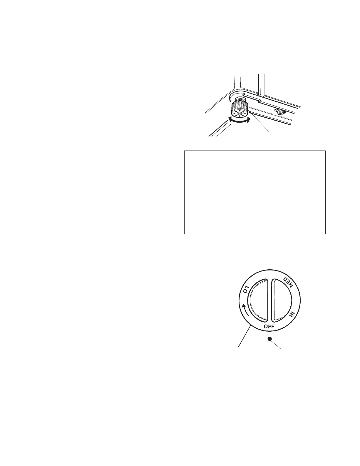
On initial switch on turn the thermostat controls in
the direction of the arrow to a LO (the coldest)
position (Figure 6). Align the position with the
marker and allow 30 minutes for the temperature
inside the chiller to stabilise (Figure 6).
If you wish to make the temperature less cold
inside the chiller, turn the thermostat control to
MED or HI.
Recommended temperatures for wine storage:
Wine type Temperature Control settings
Red wines 15–18°C HI
Dry/white wines 10–15°C MED
Sparkling wines 7–12°C LO
Rosé wines 10–12°C MED
Note: The above settings on the temperature
controls are dependent upon room temperature
and the location of the chiller.
FIGURE 6
TEMPERATURE
CONTROL MARKER
Notes on operation
During normal operation the following noises may
be heard:
OStifled murmur from compressor when it is
working.
OSoft gurgling from the coolant flowing through
the cooling system.
OClick from the thermostats switching on and
off.
The appliance is designed to operate at normal
room temperatures. Position it away from any heat
source such as a boiler, ovens and heaters which
will reduce the cooling efficiency of the chiller. It is
also not advisable to install the appliance in
unheated locations such as garages or
outbuildings, as these will impair the operation of
the chiller in winter.
The chiller requires space around the casing for
efficient cooling and operation. It is designed for
freestanding and not to be built-in.
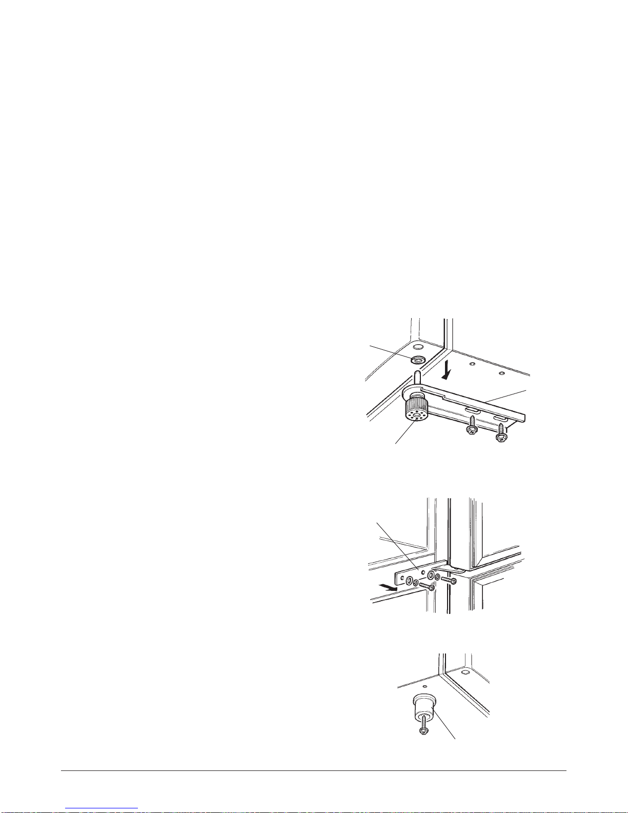
The chiller must be installed on a firm, flat and
level surface for it to work quietly and efficiently. If
necessary, turn the adjustable foot to level the
appliance (Figure 5).
Switching on
Plug the chiller into a nearby power socket and
switch on. A humming from the compressor will
indicate that the chiller is running.
Installation
Important
Make sure that the voltage marked on the rating label on the product corresponds with the voltage in your
home.
This quality product has been tested and certified to meet all applicable UK electrical and safety standards.
ADJUSTABLE FOOT
FIGURE 5
Door lock
The door locks both compartments.Turn the lock
anti-clockwise to unlock the door and clockwise to
lock. Always remember where you keep the key.

Page 5
Interior light
FIGURE 7
The interior lamp is only available in the lower
compartment.To turn the lamp to ON press the
rocker switch to ON.To turn the lamp to OFF press
the rocker switch to OFF.The lamp must be
manually turned OFF and ON.
Replacing the lamp
Unplug the chiller from the mains supply.
Remove the screw and diffuser.
Unscrew the lamp from the lampholder and replace
it with a lamp of the same type and wattage (10
Watts).
SCREW
DIFFUSER
LAMP
LAMPHOLDER
ON/OFF
SWITCH
Maintenance and cleaning
It is recommended to clean and wipe out the chiller
after any spillage inside or outside the appliance.
Use a teaspoonful of bicarbonate of soda diluted in
a pint of warm water.Wipe the internal surfaces
and shelving to remove residues. Leave to dry
before reloading.
Keep water away from the temperature controls.
Finally, wipe the door seal.
The chiller automatically keeps a constant
temperature dependent upon the thermostat
setting. Beware of the back wall as this may be
cold to the touch.
Wipe the outside casing from time to time in order
to remove dirt and dust.
Drainage channel
Water collects in the drainage channel on the back
wall located in the lower compartment.The
drainage needs to be cleaned regularly to avoid the
build up of impurities.Wipe the channel with a
damp cloth and clean out any residue from the
drainage hole (Figure 8).
Use a soft brush or vacuum cleaner to remove the
dust from behind the chiller, taking care not to
damage the pipes and wiring.
Also remove dust from the compressor motor
housing which is situated at the rear back of the
appliance casing.
Clean the collecting tray from above the
compressor motor (rear of the casing) ensuring that
the drainage pipe is also clear.
Important
The chiller must be turned off at the mains before maintaining or cleaning.
FIGURE 8 DRAINAGE
HOLE
DRAINAGE
CHANNEL
When not in use
If leaving the chiller unused for a prolonged period, unplug from mains, wipe dry and leave the doors
open.

Page 6
This product is supplied with a fitted plug which contains a 13A fuse. If
you are simply replacing the fuse, you must use a 13A fuse which has
been approved by ASTA to BS1362.
If the plug does not fit the socket or becomes damaged, a new plug must
be fitted. Replace the original plug with the correct plug for your socket. If
this is a 3-pin (square pin) 13A (BS1363) plug, you must make sure that it
is fitted with an ASTA approved 13A fuse.
If another type of plug is used, it must be protected by a 15A fuse, either in
the plug or at the distribution board.
1. Cut off the existing fitted plug.
2. The wires in the mains lead supplied with this appliance are coloured in accordance with the following
code (Figure 9):
GREEN/YELLOW = EARTH (E) BLUE = NEUTRAL (N) BROWN = LIVE (L)
This product must be earthed.
As the colours of the wires in the mains lead may not correspond with the colour markings identifying the
terminals in your new plug, proceed as follows.
The wire which is coloured GREEN or YELLOW/GREEN must be connected to the terminal which is
marked with the letter E or Esymbol or coloured GREEN orYELLOW/GREEN.
The wire which is coloured BLUE must be connected to the terminal in the plug which is marked with the
letter N or coloured BLACK or BLUE.
The wire which is coloured BROWN must be connected to the terminal which is marked with the letter L or
coloured RED or BROWN.
3. Ensure that the connections are tight and that no loose strands are left out of the terminals.
IF IN ANY DOUBT CONSULT A QUALIFIED ELECTRICIAN.
If the mains lead becomes damaged consult a qualified electrician.
Fuse and mains plug replacement
FIGURE 9
Problem Possible cause Remedy
Appliance does not run No power Check power is switched ON
Faulty fuse Check fuse in plug
Temperature control set to OFF Turn thermostat setting higher
Chiller is not cold enough Door is open for too long Do not open door needlessly
Located too near a heat source Relocate appliance
Inadequate airflow around appliance
Thermostat set too high Lower temperature by turning
control towards LO
Abnormal noise and Appliance not level Choose a level surface
vibration Cooling tubes touching cabinet Carefully ease away tubes from
or other parts other parts
Troubleshooting

Page 7
Specification
Capacity (litres) 82
Dimensions: HxWxD mm 846x472x450
Power consumption (Watts) 78
Power supply 220/240V, 50Hz
Climate class N
Refrigerant R600a
Product specification may vary without prior notice.
Safety measures
This appliance/fitting is marked according to the European directive 2002/96/EC on Waste Electrical and Electronic
Equipment (WEEE). By ensuring this product is disposed of correctly, you will help prevent potential negative consequences
for the environment and human health, which could otherwise be caused by inappropriate waste handling of this product.
The symbol on the product, or on the documents accompanying the product, the Crossed Out Wheelie Bin symbol, indicates
that this appliance/fitting may not be treated as household waste. Instead it shall be handed over to the applicable collection
point for the recycling of electrical and electronic equipment. Disposal must be carried out in accordance with local
environmental regulations for waste disposal. For more detailed information about treatment, recovery and recycling of this product,
please contact your local authority, your household waste disposal service or the retailer where you purchased the product."
After sales service
Never try to repair the appliance or the electrical parts yourself. Any repair carried out by an unskilled
person is dangerous and may affect the guarantee. Contact the Helpline below for assistance and advice.
Disposal of old chiller or fridge
Disposal of the appliance must conform with EU environmental regulations.
Cut off the mains lead and remove any door locks to ensure the appliance is beyond further use.
The appliance must be delivered to an authorised collection centre.
For Faults and Assistance
Phone: 0844 871 0011
This appliance is guaranteed for a period of two years from date of purchase against defects in materials
and workmanship only, and provided that all these user instructions have been strictly complied with.The
guarantee does not cover incidental or consequential loss, such as loss of consumables.
Where this guarantee applies, the appliance will be repaired or replaced at the manufacturer's option
without charge. If the guarantee does not apply or has expired, you will be given a quotation for cost of
repairs and any parts required.
Keep your purchase receipt with these instructions, and in the event of breakdown contact the HELPLINE
on 0844 871 0011.

CZ26139/200208
We continuously try to improve our products for the benefit of our customers.
For this reason we reserve the right to make changes to any product at any time, without notice.
Table of contents
Other Coolzone Chiller manuals
Popular Chiller manuals by other brands

Elkay
Elkay ECP8 2GQ Series Installation, care & use manual

Aqua Medic
Aqua Medic Titan 150 Operation manual

Envision
Envision NXW Series installation manual

York
York YLUA Series Operation manual

Elkay
Elkay ERS1-2F Installation, care & use manual

Hoshizaki
Hoshizaki LANCER S8E V2.5 Hi-Carb Superchiller Installation, operation & service manual

Aqua Cooler
Aqua Cooler G Series owner's manual

Thermal Care
Thermal Care Accuchiller NQ Series Operation, installation, and maintenance manual

Daikin
Daikin EWYQ080DAYN Operation manual

Fast Chiller
Fast Chiller TT3X User's Guide Care and Maintenance

McQuay
McQuay WMC-B 145S installation manual

Trane
Trane CGCN Installation operation & maintenance