Cooper Crouse-Hinds CEAG GHG 525 Series User manual

Betriebsanleitung
Operating instructions
Mode d’emploi
COOPER Crouse-Hinds GmbHCOOPER Crouse-Hinds GmbH
COOPER Crouse-Hinds GmbH
Neuer Weg - Nord 49
D 69412 Eberbach / Germany
Fone +49 (0) 6271/806 - 500
Fax +49 (0) 6271/806 - 476
Internet: http://www.CEAG.de
E-Mail: Info-ex @ ceag.de
GHG 510 7004 P0003 D/E/F (B)
Steckvorrichtungen für Industriean-
wendungen
125A, 4-polig und 5-polig,
GHG 525
Plug and socket system for
industrial use
125A, 4-pole and 5-pole,
GHG 525
Fiches et prises de
125, à 4 pôles et 5 pôles,
pour utilisation industrielle,
GHG 525
GHG 525 45
GHG 525 75

Cooper Crouse-Hinds GmbH
22
22
2
Steckvorrichtung 125A,
GHG 525
Plug and socket system
125A, GHG 525
Fiches et prises de 125A,
GHG 525
Inhalt:Inhalt:
Inhalt:Inhalt:
Inhalt:
Inhalt................................... 2
Maßbild............................... 3
Anschlussbild...................... 6
1 Technische Angaben........... 3
1.1 Steckvorrichtung GHG 525. 3
2 Sicherheitshinweise............. 4
3 Normenkonformität............. 4
4 Verwendungsbereich........... 4
5 Verwendung/
Eigenschaften..................... 4-5
6 Installation.......................... 5
6.1 Montage............................. 5
6.2 Öffnen des Gerätes/
Elektrischer Anschluss......... 5
6.3 Kabel- und Leitungs-
einführung; Verschluss-
stopfen............................... 6
6.4 Schließen des Gerätes........ 6
6.5 Inbetriebnahme.................. 6
7 Instandhaltung/Wartung 6
8 Reparatur / Instandsetzung/
Änderungen........................ 6
9 Entsorgung / Wieder-
verwertung......................... 6
10 Konformitätserklärung........ 15
Contents:Contents:
Contents:Contents:
Contents:
Contents.............................. 2
Dimensional drawings.......... 7
Connection diagram............. 10
1 Technical data...................... 7
1.1 Plug and socket GHG 525.... 7
2 Safety instructions................ 8
3 Conformity with standards... 8
4 Field of application................ 8
5 Application/Properties........... 8-9
6 Installation............................ 9
6.1 Mounting.............................. 9
6.2 Opening the device /
Electrical connection............. 9
6.3 Cable entry (KLE);
blanking plug........................ 10
6.4 Closing the device................ 10
6.5 Taking into operation............ 10
7 Maintenance/Servicing......... 10
8 Repairs/Modifications.......... 10
9 Disposal/Recycling.............. 10
10 Declaration of conformity..... 15
Contenu:Contenu:
Contenu:Contenu:
Contenu:
Contenu............................. 2
Plans cotés................. ....... 11
diagram de connexion......... 14
1 Caractéristiques
techniques......................... 11
1.1 Fiche et prise GHG 525..... 11
2 Consignes de sécurité....... 12
3 Conformité avec les
normes............................. 12
4 Domaine d’utilisation........ 12
5 Utilisation/Propriétés........ 12-13
6 Installation....................... 13
6.1 Montage........................... 13
6.2 Ouverture de l’appareil/
Raccordement électrique.. 13
6.3 Entrées de câble (KLE)
bouchons de fermeture.... 14
6.4 Fermeture de l’appareil/
Fermeture du couvercle... 14
6.5 Mise en service................ 14
7 Maintien/Entretien........... 14
8 Réparation/Remise
en état/Modifications....... 14
9 Évacuation des déchets/
Recyclage.......................... 14
10 Déclaration de conformité.... 15

Cooper Crouse-Hinds GmbH 33
33
3
1 Technische Angaben
1.11.1
1.11.1
1.1 Steckvorrichtung GHG 525Steckvorrichtung GHG 525
Steckvorrichtung GHG 525Steckvorrichtung GHG 525
Steckvorrichtung GHG 525
Nennspannung: bis 690 V, 50/60 Hz
Max. Nennstrom: 125A
Max. Vorsicherung: 125A
Schaltvermögen Wandsteckdose mit Schalter: bis 415V 500V 690V
AC 22 125 A 125 A 125 A
AC 23 90 A 70 A 50 A
Zul. Lagertemperatur in Originalverpackung: -55°C bis +80°C
Schutzart bei geschlossenem und gesichertem
Klappdeckel sowie ordnungsgemäß gesteckten
Kombinationen nach EN 60529 / IEC 529: IP 66 (Listenausführung)
Schutzklasse nach EN 60598/IEC 598: I - wird von den Geräten erfüllt
Leitungseinführung: (Listenausführung)
Wandsteckdose mit Schalter 1x M63 (Ø 35 - 46mm) + 1x Verschluss M63
Stecker / Kupplung Ø 31-58 mm
Anschlussklemme: Querschnitt Abisolierlänge der Adern
Wandsteckdose mit Schalter 1 x 10 - 70 mm² 18,00 mm
Stecker / Gerätestecker 1 x 4 - 35 mm² 13,00 mm
mit Stiftkabelschuh 1x50mm²
Flanschsteckdose / Kupplung / 1 x 16 - 70 mm² 16,00 mm
Pilotkontakt 1 x 2,5 mm² 10,00 mm
Prüfdrehmomente:
Hutmutter der KLE M63 5,0 Nm
Deckelschrauben 2,5 Nm
Anschlussklemmen 4,5 Nm
Selbstschneidende Schrauben Größe 4 2,0 Nm
Selbstschneidende Schrauben Größe 5 3,0 Nm
Anschlussschrauben des Schalters 6,0 Nm
Gewicht: (Listenausführung) 4-polig 5-polig
Wandsteckdose mit Schalter GHG 525 4. ca. 8,50 kg ca. 8,70 kg
Stecker GHG 525 7. ca. 1,30 kg ca. 1,40 kg
Flanschsteckdose GHG 525 8. ca. 1,40 kg ca. 1,50 kg
Gerätestecker GHG 525 9. ca. 0,90 kg ca. 1,00 kg
Kupplung GHG 525 3. ca. 2,00 kg ca. 2,10 kg
Steckvorrichtung 125A, GHG 525
Maßangaben in mm
X = Befestigungsmaße
Flanschsteckdose
Kupplung
Gerätestecker, 4- polig
Stecker, 4- polig
Stecker, 5- polig
Gerätestecker, 5- polig
Flanschausschnitt FlanschsteckdoseFlanschausschnitt Gerätestecker Wandsteckdose mit Schalter

Cooper Crouse-Hinds GmbH
44
44
4
2 Sicherheitshinweise
Die Steckvorrichtungen GHG 525
sind nicht für explosionsgefährdete
Bereiche geeignet.
Umbauten oder Veränderungen an den
Steckvorrichtungen sind nicht gestattet.
Sie sind bestimmungsgemäß in unbe-
schädigtem und einwandfreiem Zustand
zu betreiben.
Als Ersatz und zur Reparatur dürfen nur
Originalteile von CEAG verwendet werden.
Reparaturen dürfen nur von CEAG oder
einer qualifizierten Elektrofachkraft in
Übereinstimmung mit national geltenden
Regeln durchgeführt werden.
Vor Inbetriebnahme müssen die Steckvor-
richtungen entsprechend der im Abschnitt 6
genannten Anweisung geprüft werden.
Die Steckvorrichtungen nur mit unbeschä-
digten Steckern betreiben.
Alle Fremdkörper müssen vor der ersten
Inbetriebnahme aus den Geräten entfernt
werden.
Beachten Sie die nationalen Sicherheits-
und Unfallverhütungsvorschriften und die
nachfolgenden Sicherheitshinweise in
dieser Betriebsanleitung, die wie dieser
Text in Kursivschrift gefasst sind!
Steckvorrichtung 125A, GHG 525
3 Normenkonformität
Das Betriebsmittel ist gemäß
DIN EN ISO 9001 entwickelt, gefertigt und
geprüft worden.
Es entspricht den in der Konformitätser-
klärung aufgeführten Normen.
Weitere Anforderungen wie die Richtlinie
"Elektromagnetische Verträglichkeit
(2004/108/EG)" werden von den Steckvor-
richtungen erfüllt.
44
44
4VV
VV
Verwendungsbererwendungsber
erwendungsbererwendungsber
erwendungsbereicheich
eicheich
eich
Die Steckvorrichtungen GHG 525 nach
IEC 309 sind zum Einsatz in schweren
Industriebereichen geeignet!
Die eingesetzten Gehäusematerialien ein-
schließlich der außenliegenden Metallteile
bestehen aus hochwertigen Werkstoffen, die
einen anwendungsgerechten Korrosions-
schutz und Chemikalienresistenz in "normaler
Industrieatmosphäre" gewährleisten:
- schlagfestes Polyamid
- glasfaserverstärktes Polyester
- Edelstahl AISI 316 L.
Bei Einsatz in extrem aggressiver Atmosphäre
sind die zusätzlichen Informationen über die
Chemikalienbeständigkeit der eingesetzten
Kunststoffe dem Datenblatt
GHG 902 4001 P0001 zu entnehmen.
5 Verwendung / Eigenschaften
Die Steckvorrichtungen GHG 525 dienen zur
Stromversorgung von standortvariablen Vor-
Ort-Steuerungen, elektrischen Anlagen sowie
von beweglichen Maschinen und Antrieben in
industriellen Bereichen. Sie sind nach IEC bis
max. 125A einsetzbar (siehe techn. Daten).
Die Steckvorrichtungen sind generell für den
in der IEC 309 festgelegten Spannungsbereich
einsetzbar (z.B. UN400V das entspricht dem
Spannungsbereich 380 - 415V).
Das am Stecker angeschlossene Betriebs-
mittel muss für die anliegende Netzspan-
nung geeignet sein.
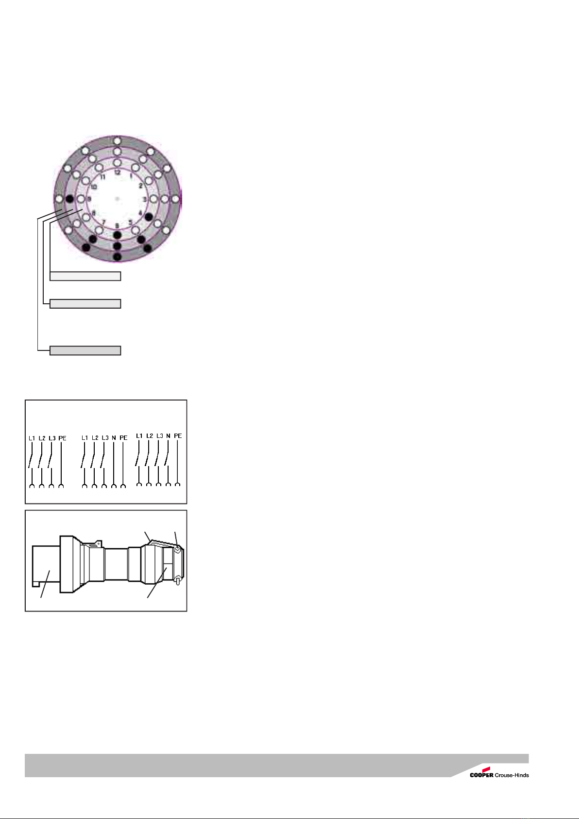
Bild 1: Zur Inbetriebnahme der Steckdosen
sowie der Kupplung, muss zuerst der
Bajonettring Pos 2 von der Steckdose Pos. 1
aufgeschraubt und aufgeklappt werden.
Bild 2: Nach dem Stecken des Steckers in
die Steckdose wird, um die Schutzart IP 66
herzustellen, der Bajonettring des Steckers
Pos. 2 auf die Steckdose bis zum Anschlag
aufgedreht.
Zum Betreiben der Wandsteckdose mit
Verriegelungsschalter ist wie folgt vorzugehen:
Bild 1 und Bild 2: Wie oben beschrieben
Bild 3: Danach wird der Schalter Pos 3,
eingeschaltet und somit der Stecker in der
Steckdose verriegelt.
Zum Ausschalten und Ziehen des Steckers
aus der Wandsteckdose mit Schalter ist in
umgekehrter Reihenfolge vorzugehen.
Nach dem Trennen des Steckers von der
Steckdose ist, um die Schutzart IP 66
herzustellen, die Steckdose mit dem Klapp-
deckel zu schließen und mit dem Bajonettring
zu sichern.
Das Stecken und Trennen des Steckers von
der Wandsteckdose mit Schalter ist nur im
ausgeschalteten Zustand möglich.
Die Verantwortung hinsichtlich bestim-
mungsgemäßer Verwendung dieser
Steckvorrichtung liegt allein beim Betreiber.
Nach einem Kurzschluss im Stromkreis ist
die Funktionsfähigkeit zu überprüfen.
Angaben aus Punkt 3 und 4 sind bei der
Verwendung zu berücksichtigen.
Andere als die beschriebenen Anwendun-
gen sind ohne schriftliche Erklärung der Fa.
CEAG nicht zulässig.
Beim Betrieb sind die in der Betriebsanlei-Beim Betrieb sind die in der Betriebsanlei-
Beim Betrieb sind die in der Betriebsanlei-
tung unter Punkt 7 genannten Anweisun-tung unter Punkt 7 genannten Anweisun-
tung unter Punkt 7 genannten Anweisun-
gen zu beachten.gen zu beachten.
gen zu beachten.
Bild 1
Bild 2
Pos 1
Pos 2
Pos 2
Pos 3
Bild 3

Cooper Crouse-Hinds GmbH 55
55
5
Steckvorrichtung 125A, GHG 525
Die Isolation der Anschlussleitungen muss
bis an die Klemme heranreichen. Der Leiter
selbst darf nicht beschädigt sein.
Die minimal und maximal anschließbaren
Leiterquerschnitte sind zu beachten (siehe
technische Daten).
Die ordnungsgemäß abisolierten Anschluss-
leitungen der Kabel sind unter Berücksichti-
gung einschlägiger Vorschriften anzuschlie-
ßen.
Der elektrische Anschluss der Stecker
erfolgt wie in Bild 4 und 5 dargestellt:
Der Steckereinsatz, Pos. 2, ist durch lösen der
Befestigungsschrauben, Pos. 3, aus der
Steckerhülse, Pos. 1, herauszunehmen.
Danach kann der Steckereinsatz, Pos 2, an
den Anschlüssen der Steckerstifte, Pos L1, ...
und PE, angeschlossen werden.
Achtung: Bei Verlust der Befestigungs-
schrauben, Pos. 3, Bild 4, sind diese durch
gleichartige Schrauben zu ersetzen, oder
direkt vom Hersteller anzufordern.
Typ Größe 5 = KTG 50 x 50 x 50 / 25.
Der Zusammenbau erfolgt nach dem
Kabelanschluss in umgekehrter Reihenfolge.
Der elektrische Anschluss der Gerätestek-
ker erfolgt wie in Bild 6 bis 8 dargestellt:
Bild 6:
Der Steckereinsatz, Pos 2, wird durch Lösen
der zwei Schrauben, Pos 3, aus dem Geräte-
flansch, Pos 2, entnommen.
Bild 7:
Nun können die Anschlussleitungen, Pos 4, an
den Anschlussklemmen,L1... und PE, des
Steckereinsatzes, Pos 2, wie unter Punkt 6.2
beschrieben, angeschlossen werden.
Bild 8:
Zum Schluss wird der Steckereinsatz, Pos. 2,
mit den Formschrauben, Pos. 3, in den
Geräteflansch, Pos. 1, lagerichtig einge-
schraubt.
Alle Schrauben und/oder Muttern der
Anschlussklemmen, auch die der nicht
benutzten, sind fest anzuziehen.
Bei übermäßigem Anziehen der Anschluss-
schrauben kann der Anschluss beeinträchtigt
oder beschädigt werden.
Die Anschlussklemmen sind für den Anschluss
von Kupferleitern ausgelegt.
Bei der Verwendung von mehr- oder fein-
drähtigen Anschlusskabel /-leitungen sind die
Aderenden entsprechend den geltenden
nationalen Vorschriften zu behandeln (z.B.
Verwendung von Aderendhülsen).
Pos 2 Pos 1
Bild 6
6 Installation
Für das Errichten / Betreiben sind die
relevanten nationalen Vorschriften sowie die
allgemein anerkannten Regeln der Technik
maßgebend.
UnsachgemäßeInstallation und Betrieb der
Steckvorrichtung kann zum Verlust der
Garantie führen.
6.1 Montage
Die Montage der Wandsteckdosen kann ohne
Öffnen der Gehäuse erfolgen.
Die Wandsteckdosen dürfen bei der Direkt-
montage an der Wand nur an den vorgesehe-
nen Befestigungspunkten eben aufliegen. Die
gewählte Schraube muss der Befestigungs-
öffnung angepasst sein (siehe Maßbilder) und
sie darf die Öffnung nicht beschädigen (z.B.
Verwendung einer Unterlegscheibe).
Das Gerät ist mit mindestens 2 Schrauben
diagonal zu befestigen.
Die Wandsteckdosen und Flanschsteckdosen
sind so zu montieren, dass die Stecköffnung
nicht nach oben zeigt.
Bei übermäßigem Anziehen der Schrauben
kann das Gerät beschädigt werden.
Pos 1
Die Stecker sind im Freien vorzugsweise mit
der Steckeröffnung (Stiftseite) nach unten
aufzubewahren bzw. mit optional erhältlichen
Steckerschutzkappen zu verschließen.
Pos 3 Pos 3
Bild 4
Bild 8
Bild 5
Bild 7
Pos 2 Pos 1 Pos 4 Pos 2 Pos 1
Pos 1
Pos 2
L2 L3
L1 N
PE
Pos 2
Pos 3
Pos 3
Pos 3
6.2 Öffnen des Gerätes /
Elektrischer Anschluss
Der elektrische Anschluss des Betriebsmit-
tels darf nur durch Fachpersonal erfolgen.
Vor öffnen der Geräte ist die Spannungs-
freiheit sicherzustellen bzw. sind geeignete
Schutzmaßnahmen zu ergreifen.
Pos 2 Pos 3 Pos 1

Cooper Crouse-Hinds GmbH
66
66
6
Steckvorrichtung 125A, GHG 525
Codierung der Spannung und Polzahl
nach IEC
Spannung Farbe h (PE)
2-polig + PE
110 - 130V 50/60Hz gelb 4 Uhr
200 - 250V 50/60Hz blau 6 Uhr
3-polig + PE
200 - 250V 50/60Hz blau 9 Uhr
480 - 500V 50/60Hz schwarz 7 Uhr
380 - 415V 50/60Hz rot 6 Uhr
600 - 690V 50/60Hz schwarz 5 Uhr
3-polig + N + PE
480 - 500V 50/60Hz schwarz 7 Uhr
380 - 415V 50/60Hz rot 6 Uhr
600 - 690V 50/60Hz schwarz 5 Uhr
6.5 Inbetriebnahme
Vor Inbetriebnahme des Betriebsmittels sind
die in den einzelnen nationalen Bestimmungen
genannten Prüfungen durchzuführen.
Außerdem ist vor der Inbetriebnahme die
korrekte Funktion und Installation des
Betriebsmittels in Übereinstimmung mit dieser
Betriebsanleitung und anderen anwendbaren
Bestimmungen zu überprüfen.
Vor jedem Stecken des Steckers in die
Steckdose ist dieser auf Beschädigungen zu
überprüfen.
Der Betreiber muss dafür sorgen, dass beim
Betrieb der Steckvorrichtung überall ein
gleiches Erdpotential anliegt.
Unsachgemäße Installation und Betrieb der
Steckvorrichtungen kann zum Verlust der
Garantie führen.
7 Instandhaltung / Wartung
Vor Öffnen des Gehäuses Spannungs-
freiheit sicherstellen oder geeignete
Schutzmaßnahmen ergreifen.
Die erforderlichen Wartungsintervalle sind
anwendungsspezifisch und daher in Abhän-
gigkeit von den Einsatzbedingungen vom
Betreiber festzulegen.
Sollte bei einer Wartung festgestellt werden,
daß Instandsetzungsarbeiten erforderlich sind,
ist Abschnitt 8 dieser Betriebsanleitung zu
beachten.
8 Reparatur / Instand-
setzung / Änderungen
Instandsetzungsarbeiten / Reparaturen dürfen
nur mit CEAG Originalersatzteilen vorgenom-
men werden.
Umbauten oder Änderungen am Betriebs-
mittel sind nicht gestattet.
9 Entsorgung / Wiederver-
wertung
Bei der Entsorgung des Betriebsmittels sind
die jeweils geltenden nationalen Abfall-
beseitigungsvorschriften zu beachten.
Zur Erleichterung der Wiederverwertbarkeit
von Einzelteilen sind Kunststoffteile mit dem
Kennzeichen des verwendeten Kunststoffes
versehen.
Programmänderungen und -ergänzungen sind
vorbehalten.
6.4 Schließen des Gerätes
Zur Sicherstellung der Schutzart sind die
Deckelschrauben, die Schrauben der Stecker
und der Kupplung fest anzuziehen.
Bei übermäßigem Anziehen kann die
Schutzart beeinträchtigt werden.
Alle Fremdkörper sind aus dem Gerät zu
entfernen.
Pos 1 Pos 2
Bild 9
Anschlussbilder mit Schalter
Pos 3 Pos 4
3-polig+PE 3-polig + N + PE
Standard Optional
Beim Einsatz von KLE mit einer niedrigeren als
der für das Gerät zutreffenden IP-Schutzart,
(siehe Seite 3 technische Daten) wird die IP-
Schutzart des gesamten Gerätes reduziert.
Die für die eingesetzten KLE maßgebenden
Montagerichtlinien sind zu beachten.
Nicht benutzte Einführungsöffnungen sind mit
einem Verschlussstopfen zu verschließen, um
die Schutzart sicherzustellen.
Es ist darauf zu achten, dass bei der Installati-
on der KLE die für den Leitungsdurchmesser
geeigneten Dichtungseinsätze verwendet
werden.
Bei ausschneidbaren Dichtungseinsätzen ist
sicherzustellen,dass der Einsatz ordnungsge-
mäß dem Leitungsdurchmesser angepasst
wird.
Zur Sicherstellung der Schutzart sind die
KLE fest anzuziehen.
Bei übermäßigem Anziehen kann die
Schutzart beeinträchtigt werden.
Achtung: Metallflansche, Metallplatten und
Metallverschraubungen müssen in den
Potentialausgleich miteinbezogen werden.
6.3.2 Stecker und Kupplung
Bild 9:
Es dürfen generell nur die im Stecker und der
Kupplung vorhandenen Dichteinsätze verwen-
det werden.
Bei der Installation der Leitung ist darauf zu
achten, dass die für den Leitungsdurchmesser
geeigneten Dichtungseinsätze verwendet
werden.
Nach dem Anschluss der Leitung ist die
Überwurfmutter Pos 2, handfest bis zur
Erzielung der Dichtwirkung anzuziehen.
Danach sind die Schrauben Pos 4, der
Zugentlastung Pos 3, fest anzuziehen.
Achtung! Übermäßiges Anziehen kann die
Zugentlastungswirkung negativ beeinträch-
tigen bzw. das Anschlusskabel beschädi-
gen.
6.3 Kabel- und
Leitungseinführungen
(KLE); Verschlussstopfen
6.3.1 Steckvorrichtung:
Für bewegliche Leitungen sind Trompeten-
verschraubungen oder andere geeignete
Einführungen mit zusätzlicher Zug-
entlastung zu verwenden.

Cooper Crouse-Hinds GmbH 77
77
7
Plug and socket system 125A, GHG 525
Dimensions in mm
X = fixing dimensions
1 Technical data
1.11.1
1.11.1
1.1 Plug and socket GHG 525Plug and socket GHG 525
Plug and socket GHG 525Plug and socket GHG 525
Plug and socket GHG 525
Rated voltage: up to 690 V, 50/60 Hz
Rated current: max. 125A
Back-up fuse: max. 125A
Switching capacity wall socket with switch: up to 415V 500V 690
AC 22 125 A 125 A 125 A
AC 23 90 A 70 A 50 A
Perm. storage temperature in original packing: -55°C to +80°C
Protection category acc. to EN 60529 / IEC 529
with closed and secured hinged cover as well
as combinations properly plugged together: IP 66 (catalogue version)
Insulation class acc. to EN 60598/IEC 598: I - is complied with by the devices
Cable entries: (catalogue version)
Wall socket with switch 1x M63 (Ø 35-46mm) +1 x blanking plug M63
Plug / Coupler Ø 31-58mm
Supply terminal: Cross section Stripped wire length
Wall socket with switch 1 x 10 - 70 mm² 18 mm
Plug 1 x 4.00 - 35 mm² 13 mm
with pin cable lug 1x 50 mm²
Flange socket / Coupler 1 x 16 - 70 mm² 16 mm
Pilot contact 1x 2.5 - 4.00 mm² 10 mm
Test torques:
Cap nut of the M63 entry 5.0 Nm
Cover screws 2.5 Nm
Terminals 4.5 Nm
Self-cutting screws size 4 2.0 Nm
Self-cutting screws size 5 3.0 Nm
Switch connection screw 6.0 Nm
Weight: (catalogue version) 4-pole 5-pole
Wall socket with switch GHG 525 4. approx. 8.50 kg 5.60 kg
Plug GHG 525 7. approx. 1.30 kg 1.40 kg
Flange socket GHG 525 8. approx. 1.40 kg 1.50 kg
Inlet GHG 525 9. approx. 0.90 kg 1.00 kg
Coupler GHG 525 3. approx. 2.00 kg 2.10 kg
Flange socket
Coupler
Inlet, 4- pole
Plug, 4- pole
Plug, 5- pole
Inlet, 5- pole
Drilling template for flange socketsDrilling template for inlets Wall socket with switch

Cooper Crouse-Hinds GmbH
88
88
8
2 Safety instructions
The GHG 525 plugs and sockets
are not suitable for explosion
hazardous areas.
Modifications to the plugs and sockets or
changes of their design are not permitted.
They shall be used for their intended
purpose and in perfect and clean condition.
For replacement and repair only genuine
CEAG spare parts shall be used.
Repairs that affect the explosion protection,
may only be carried out by CEAG or a qualified
electrician in compliance with the respective
national regulations.
Prior to taking the plugs and sockets into
operation, they will have to be checked in acc.
with the instruction as per section 6.
The sockets may only be used in
undamaged condition.
Before the initial operation, any foreign
matter will have to be removed from the
the plugs and sockets.
Observe the national safety rules and
regulations for prevention of accidents as
well as the safety instructions included in
these operating instructions and set in
italics the same as this text!
Plug and socket system 125A, GHG 525
3 Conformity with standards
The apparat is conform to the standards
specified in the EC-Declaration of conformity.
It has been designed, manufactured and
tested according to the state of the art and to
DIN EN ISO 9001.
The apparats fulfil further requirements, such
as the EC directive on electromagnetic
compatibility (2004/108/EEC)
4 Field of application
The plugs and sockets GHG 525, acc to.
IEC 309 are suitable for use in heavy industrial
areas !
The enclosure materials employed, including the
exterior metal parts, are made of high-quality
materials which ensure a corrosion protection and
resistance to chemical substances corresponding
to the requirements in a “normal industrial
atmosphere”:
- impact resistant polyamide
- glass-fibre reinforced polyester
- special steel AISI 316 L
In case of use in an extremely aggressive
atmosphere, the additional data on the
employed plastic materials’resistance against
chemicals will have to be taken from the data
sheet GHG 902 4001 P0001.
5 Use/Properties
The GHG 525 plugs and sockets are used for
the power supply of local controls with varying
locations, as well as of electrical installations,
mobile machinery and driving gear in industrial
areas. Acc. to IEC they are used up to max.
125A (see page 7, Technical data).
The plugs and sockets can generally be used
for the voltage range laid down in IEC 309
(e.g. UN 400V that corresponds to the voltage
range 380-415V).
The apparatus connected to the plug shall
be suitable for the applied mains voltage.
Fig. 1:
In order to activate the sockets, first the
bayonet ring item 2 is to be screwed off the
socket item 1 and to be folded open.
Fig. 2:
After pushing the plug into the socket, the
bayonet ring of the plug item 2 is screwed to
its stop onto the socket in order to establish
IP 66 protection category.
For operating the 4-pole wall socket (with
interlocking switch) proceed as follows:
Fig. 1 + fig. 2:
As described above.
Fig. 3:
The switch item 3 is switched on, thereby
locking the plug in the socket.
Proceed in inverse order to switch off and pull
the plug from the wall socket with switch.
After having removed the plug from the
socket, close the latter with the folding cover
and secure it with the bayonet ring in order to
establish IP 66 type of protection.
The plug can be pushed into the socketThe plug can be pushed into the socket
The plug can be pushed into the socket
and pulled out of it only whilst the walland pulled out of it only whilst the wall
and pulled out of it only whilst the wall
socket with switch is switched ofsocket with switch is switched of
socket with switch is switched off.f.
f.f.
f.
The user alone is responsible for the
appropriate use of this plug and socket
system.
After a short in the circuit, the
operativeness has to be checked.
The data as per point 3 and 4 will have to
be taken into account with the use.
Applications other than described are not
permitted without CEAG’s prior written
consent.
For the operation, the instructions stated in
section 7 of the operating instructions will
have to be observed.
Fig. 1
Fig. 2
Item 1
Item 2
Item 2
Item 3
Fig. 3

Cooper Crouse-Hinds GmbH 99
99
9
Plug and socket system 125A, GHG 525
6 Installation
For the mounting and operation, the
respective national regulations (e. g. ElexV,
equipment safety law for Germany) as well as
the general rules of engineering will have to be
observed.
The improper installation and operation of
safety switches may result in the
invalidation of the guarantee
6.1 Mounting
The wall sockets can be mounted without
opening their enclosure.
In case the wall sockets are mounted directly
onto the wall, they may rest evenly only at the
respective fastening points. The chosen screw
shall match the fastening hole (see dimensio-
nal drawing) and it must not damage the hole
(e. g. use of a washer).
The device shall be fastened diagonally with
at least 2 screws.
The wall sockets and flange sockets shall be
mounted so that the plug hole does not point
upwards.
If the screws are overtightened, the apparatus
may be damaged.
In the open air, the plugs must be kept with
the plug opening (pin side) pointing down-
wards or be closed with protective plug caps
available as an optional extra (see general
catalogue).
Before opening the apparatus, ensure that
it has been isolated from the voltage
supply, or take appropriate protective
meassures.
The insulation of the conductors shall
reach up to the terminal. The conductor
itself shall not be damaged.
The connectible min. and max. conductor
cross-sections shall be observed (see
technical data).
Taking into account the respective regulations,
the properly bared conductors of the cables
shall be connected.
The electrical connection of the plugs is
established as shown in fig. 4 and 5:
The plug insert (item 2, fig. 5) is removed from
the pin bushing (item 1, fig. 5), after the
fastening screws (item 3, fig. 4) have been
unscrewed. Thereafter, the plug insert can be
connected to the connections of the plug pins
(see view 1, fig. 5).
Attention: When the fastening screws (item
3, fig. 4) get lost, they will have to be
replaced by similar screws or to be ordered
directly from the manufacturer.
Type: Size 5 = KTG 50 x 50 x 50 / 25
Assembly is made in inverse order, after the
cable has been connected.
The inlets are electrically connected as
shown in fig. 6 through 8.
Fig. 6:
After unscrewing the two screws item 3, the
plug insert item 2 is removed from the flange
item 2.
Fig. 7:
Now the connecting leads item 4 can be
connected to the terminal L1... and PE als of
the plug insert item 2 as described in point
6.2.
Fig. 8:
Finally, using the self-cutting screws item 3,
the plug insert item 2 is screwed into the
flange, observing its proper position.
All screws and/or nuts of the supply
terminals, also of those remaining vacant,
shall be tightened down.
Excessive tightening may affect or damage
the connection.
The supply terminals are designed for the
connection of copper conductors. If multi- or
fine-wire connecting cables are used, the wire
ends will have to be handled in acc. with the
applicable national and international rules (e.g.
use of sleeves for strands).
Item 2 Item 1
Fig. 6
Item 1
Item 3 Item 3
Fig. 4
Fig. 8
Fig. 5
Fig. 7
Item 2 Item 1 Item 4 Item 2 Item 1
Item 1
Item 2
L2 L3
L1 N
PE
Item 2
Item 3
Item 3
Item 3
Item 2 Item 3 Item 1
6.2 Opening the device/
Electrical connection
The electrical connection of the device may
only be carried out by skilled staff.

Cooper Crouse-Hinds GmbH
1010
1010
10
Plug and socket system 125A, GHG 525
Code for voltage and No. of poles
acc. to IEC
Clock
face
Voltage Colour (PE)
2-pole + PE
110 - 130V 50/60Hz yellow 4 h
200 - 250V 50/60Hz blue 6 h
3-pole + PE
200 - 250V 50/60Hz blue 9 h
480 - 500V 50/60Hz black 7 h
380 - 415V 50/60Hz red 6 h
600 - 690V 50/60Hz black 5 h
3-pole + N + PE
480 - 500V 50/60Hz black 7 h
380 - 415V 50/60Hz red 6 h
600 - 690V 50/60Hz black 5 h
6.5 Taking into operation
Prior to taking the apparatus into operation,
the tests specified in the relevant national
regulations shall be carried out. Apart from
that, the correct functioning and installation of
the apparatus in accordance with these
operating instructions and other applicable
regulations will have to be checked.
Check the plug for any damages before
putting it in the socket.
The user must ensure that a uniform
equipotential earth applies throughout when
the plug and socket system is operated.
The inappropriate installation and
operation of the plugs and sockets can
entail the loss of warranty.
7 Maintenance/Servicing
Before opening the enclosure, make sure
that the device is disconnected from the
voltage, or take appropriate protective
measures.
The required maintenance intervals depend on
the specific application and will therefore have
to be determined by the user dependent on
the conditions of use.
If during servicing, repairs prove to be
necessary, section 8 of these operating
instructions will have to be observed.
8 Repair/Overhaul/
Modifications
Repairs and overhaul may only be carried out
with genuine CEAG spare parts.
Modifications to the device or changes of
its design are not permitted.
9 Disposal/Recycling
When the apparatus is disposed of, the
respective national regulations on waste
disposal will have to be observed. In order to
facilitate the recycling of individual
components, plastic parts are provided with
the identification mark of the plastic material
used.
Subject to modifications or supplement of the
product range
6.4 Closing the device
In order to ensure the required minimum
protection category, the cover screws, the
screws of the plug and of the coupler shall be
tightened down.
Overtightening might impair the protection
category.
Any foreign matter shall be removed from
the device.
When using cable entries with a lower IP
protection than that which applies to the
device (see page 7, technical data), the IP
protection of the whole device will be reduced.
The mounting directives applicable to the
cable entries used shall be observed.
Unused holes shall be closed with a blanking
plug in order to establish the minimum
protection category.
In case of sealing inserts that are cut out, it
shall be ensured that the insert is properly
adapted to the cable diameter.
Care has to be taken that when fitting the
cable entries, sealing inserts appropriate to
the cable diameter are used.
In order to ensure the required minimum
protection category, the cable glands are to
be tightened down.
Overtightening might impair the protection
category.
Attention: Metal flanges, metal plates and
metal cable glands shall be included in the
equipotential earth connection.
6.3.2 Plug and coupler
Fig. 9:
In general, only the sealing inserts fitted in the
plug and coupler may be used.
When mounting the cable, attention has to be
paid that sealing inserts matching the cable
diameter be used.
After having connected the cable, the
coupling ring item 2 is to be screwed
fingertight until the sealing effect is obtained.
Then the screws item 4 of the pull-relief, item
3, are to be tightened down.
Mind! Overtightening might impair the pull-
relief effect!
Contact arrangement with switch
3-pole+PE 3-pole + N + PE
Standard Optional
Item 1 Item 2
Fig. 9 Item 3 Item 4
6.3 Cable entries (KLE);
blanking plugs
6.3.1 Plug and socket
Flexible cables shall be used with trumpet-
shaped cable glands or other suitable
entries with additional pull-relief.

Cooper Crouse-Hinds GmbH 1111
1111
11
1 Caracteristiques techniques
1.11.1
1.11.1
1.1 Fiche et prise GHG 525Fiche et prise GHG 525
Fiche et prise GHG 525Fiche et prise GHG 525
Fiche et prise GHG 525
Tension nominale: jusqu’à 690VCA, 50/60 Hz
Courant nominal: 125A au maxi
Fusible maximal placé en amont: 125A au maxi
Puissance de cupre: 415V 500V 690V
Prise murale avec interrupteur AC 22 125A 125A 125A
AC 23 90A 70A 50A
Température de stockage dans l’emballage original: -55°C bis +80°C
Indice de protection selon EN 60529/CEI 529,
avec le couvercle rabattant fermé et arrêté et
les dispositifs dûment enfichés: IP 66 (standard catalogue)
Classe d’isolation selon EN 60598 / CEI 598: I - est remplie par les dispositifs
Entrée de câble: (standard catalogue)
Prise murale avec interrupteur 1x M63 (Ø 35-46mm)+1xbouchon de fermeture
Fiche / Coupleur Ø 19 - 34 mm
Borne de connexion: Section transv. Longueur dénudée des fils
Prise murale avec interrupteur 1 x 10 - 70 mm² 18 mm
Connexion de la fiche 1 x 4,00 - 35 mm² 13 mm
avec cosse - cheville de câble 1 x 50 mm²
Prise encastrable / Coupleur 1 x 16 - 70 mm² 16 mm
Contact pilote 1 x 2,5 mm²
Torques d’essai:
Ecrou borgne de l’entrée de câble M63 5,0 Nm
Vis de couvercle 2,5 Nm
Bornes de connexion 4,5 Nm
Vis auto-taraudeuse taille 4 2,0 Nm
Vis auto-taraudeuse taille 5 3,0 Nm
Vis de connexion de la interrupteur 6,0 Nm
Poids: (standard catalogue) 4-pôles 5-pôles
Prise murale avec interrupteur GHG 524 4. ca. 8,50 kg ca. 8,70 kg
Fiche GHG 524 7. ca. 1,30 kg ca. 1,40 kg
Prise encastrable GHG 524 8. ca. 1,40 kg ca. 1,50 kg
Connecteur GHG 524 9. ca. 0,90 kg ca. 1,00 kg
Coupler GHG 524 3. ca. 2,00 kg ca. 2,10 kg
Fiches et prises de 125A, GHG 525
Dimensions en mm
X = dimensions de fixation
Prise encastrable
Coupleur
Connecteur, 4- pôles
Fiche, 4- pôles
Fiche, 5- pôles
Connecteur, 5- pôles
Gabarit de perçage pour prise encastrable Prise murale sans interrupteurGabarit de perçage pour connecteur

Cooper Crouse-Hinds GmbH
1212
1212
12
2 Consignes de sécurité
Les fiches et prises du type GHG 525
ne doivent pas être utilisées en
atmosphére explosive.
Il n’est pas admis de transformer ou de
modifier les fiches et prises.
Elles ne doivent être employées que pour la
fonction qui leur est dévolue et qu’en parfait
état de propreté et de fonctionnement.
Seules des pièces de rechange homologuées
d’origine CEAG devront être utilisées comme
remplacement et pour des réparations.
Des réparations qui portent sur la
protection contre l’explosion, ne devront
être exécutées que par CEAG ou par un
électricien qualifié en conformité avec la
règlementation nationale en vigueur.
Avant leur mise en service, les fiches et
prises doivent être vérifiées selon
l’instruction donnée dans la section 6.
Les prises ne doivent être utilisées qu’avec
les fiches y appartenants et en parfait état.
Avant la première mise en service, tout
corps étranger doit être ôté des appareils.
Respectez les prescriptions nationales de
sécurité et de prévoyance contre les
accidents ainsi que les consignes de
sécurité qui suivent dans ce mode d’emploi
et qui sont mises en italique comme ce
texte!
Fiches et prises de 125A, GHG 525
3 Conformité avec les normes
Les boîtes à bornes ont été conçues,
fabriquées et contrôlées suivant
DIN EN ISO 9001.
Les Appareils sont conformes aux normes
reprises dans la déclaration de conformité.
De Appareils de commande répondent à
d’autres exigences comme par exemple,
celles de la directive CE “Compatibilité
électromagnétique” (2004/108/CEE).
4 Domaine d’utilisation
Les fiches et prises selon CEI 309, du type
GHG 525, conviennent à l’emploi en
atmosphère industrielle!
Pour l’enveloppe, y compris les pièces
métalliques extérieures, des matières de qualité
supérieure ont été employées qui assurent une
protection appropriée contre la corrosion et une
résistance contre des agents chimiques en
“atmosphère industrielle normale”:
- polyamide résistant au choc
- polyester renforcé par fibre de verre
- acier spécial AISI 316
En cas d’utilisation dans une ambiance
extrêmement agressive, des informations
supplémentaires au sujet de la résistance
contre des agents chimiques des matières
plastiques employées se trouvent dans la
fiche technique GHG 902 4001 P0001.
5 Utilisation/Propriétés
Les fiches et prises GHG 525 servent à
l’alimentation en courant de réglages
automatiques en place à emplacement
variable et d’installations électriques ainsi que
de machines et de mécanismes de comman-
de mobiles en atmosphère industrielle.
Elles peuvent être exploitées jusqu’à 125A au
maxi selon CEI (voir Caractéristiques
techniques).
Les prises et fiches sont utilisables dans les
fourchettes de tension comprises dans la
norme CEI 309 (par exemple, UN 400V
appartient à la fourchette 380 - 415V).
L’ appareil connecté à la fiche doit être
adapté à la tension du réseau
correspondant.
Fig. 1: Pour la mise en circuit de lesprises, il
faut d’abord dévisser l’anneau à baïonnette,
pos. 2 de la prise, pos. 1, et le déplier.
Fig. 2: Après avoir en fiché la fiche dans la
prise, l’anneau à baïonnette, de la fiche,
pos. 2, est vissé jusqu’à sa butée sur la prise
afin d’établir l’indice de protection IP 66.
Pour la mise en circuit de la prise murale
avec interrupteur de verouillage procédez
comme suit:
Fig. 1 et fig. 2, comme décrit ci-dessus.
Fig. 3: Puis, l’interrupteur pos. 3 est
enclenché et, par conséquent, la fiche est
bloquée dans la prise.
Pour la mise hors circuit et pour retirer la fiche
de la prise murale à 4 pôles, procédez dans
l’ordre inverse.
Après avoir séparé la fiche de la prise, celle-ci
doit être fermée avec le couvercle à charnière
et bloquée avec l’anneau à baïonnette, afin
d’établir l’indice de protection IP 66.
La fiche ne peut être enfichée dans la prise
ou retirée de celle-ci que lorsque la prise
est mise hors circuit.
Seul l’utilisateur est responsable de
l’emploi comme prévu de cette fiche et
prise.
Après un court-circuit dans le circuit, la
capabilité de fonctionner doit être vérifiée.
Pour l’emploi, les consignes des sections 3
et 4 devront être respectées.
Des emplois autres que ceux décrits ne
sont admis qu’avec le consentement par
écrit de la part de CEAG.
Lors de l’utilisation, les instructions selon
le point 7 de ce mode d’emploi doivent être
respectées
Fig. 1
Fig. 2
Pos 1
Pos 2
Pos 2
Pos 3
Fig. 3

Cooper Crouse-Hinds GmbH 1313
1313
13
Fiches et prises de 125A, GHG 525
6 Installation
Pour l’installation et l’exploitation d’appareils
électriques pour atmosphère explosive, la
règlementation nationale en vigueur ainsi que
les règles de la technique généralement
reconnues devront être respectées.
L’installation et l’exploitation inadéquates
des fiches et prises peuvent entraîner la
perte de la garantie.
6.1 Montage
Le montage des prises murales peut se faire
sans ouvrir l’enveloppe.
En cas de montage directement au mur, les
prises murales ne doivent reposer au niveau
du mur qu’en les points de fixation prévus. La
vis choisie doit correspondre au trou de
fixation (voir plan coté) et elle ne doit pas
avarier l’ouverture (par ex. emploi d’une
rondelle). Le dispositif doit être fixé en
diagonale avec au moins deux vis.
Le montage de la prise murale et de la prise à
bride doit se faire de sorte que l’ouverture
d’enfichage ne soit pas dirigée vers le haut.
Un serrage excessif vis peut endommager
l’appareil.
En plein air, les fiches doivent être gardées avec
leur ouverture (côté des broches) vers le bas.
A l’option, elles peuvent être fermées avec les
capuchons protecteurs pour la fiche qui sont
disponibles sur demande (voir catalogue général).
L’isolation doit couvrir le conducteur
jusqu’à la borne. Le conducteur lui-même
ne doit pas être endommagé.
Les sections minimales et maximales
admissibles des conducteurs doivent être
respectées (voir caractéristiques
techniques).
En tenant compte des règlements respectifs,
les conducteurs dûment dénudés des câbles
sont raccordés.
Le raccordement électrique des fiches se
fait comme montré dans les figures 4 et 5.
Les vis de fixation (pos. 3, fig. 4) de l’insert de
la fiche (pos. 2, fig. 5) sont desserrées pour le
sortir de l’alvéole. Puis, l’insert peut être
raccordé aux connexions des contacts L1, ....
et PE mâles (voir vue 1, fig. 5).
Attention: En cas de perte des vis de
fixation (pos. 3, fig. 4) celles-ci doivent être
remplacées par des vis similaires ou être
demandées au fabricant.
Type taille 5 = KTG 50x50/25.
Après le raccordement du câble, le montage
se fait dans l’ordre inverse.
Le raccordement électrique des
connecteurs se fait comme montré dans
les figures 6 à 8:
Fig. 6:
Après avoir dévissé les deux vis pos. 3,
l’insert de commutation pos. 2 est sorti de la
bride pos. 2.
Fig. 7:
Puis, les fils d’alimentation pos. 4 peuvent
être raccordés aux bornes de l’insert de
commutation pos. 2, comme décrit sous point
6.2.
Fig. 8:
Enfin, l’insert de commutation pos. 2 est vissé
dans la bride pos. 1 au moyen des vis auto-
taraudeuses pos. 3 tout en respectant sa
position correcte.
Toutes les vis et/ou écrous des bornes de
connexion, aussi celles des bornes non
utilisées, doivent être serrées à fond.
Un serrage excessif vis peut endommager
l’appareil.
Les bornes sont prévues pour le raccor-
dement de conducteurs en cuivre.
En cas d’utiliser des câbles de connexion
multifilaires ou à fils de faible diamètre, les
bouts de fil doivent être traités selon la
règlementation nationale et internationale y
applicable (par ex. emploi des embouts).
Pos 2 Pos 1
Fig. 6
Pos 1
Pos 3 Pos 3
Fig. 4
Fig. 8
Fig. 5
Fig. 7
Pos 2 Pos 1 Pos 4 Pos 2 Pos 1
Pos 1
Pos 2
L2 L3
L1 N
PE
Pos 2
Pos 3
Pos 3
Pos 3
Pos 2 Pos 3 Pos 1 6.26.2
6.26.2
6.2 OuverturOuvertur
OuverturOuvertur
Ouverture du dispositif/e du dispositif/
e du dispositif/e du dispositif/
e du dispositif/
RaccorRaccor
RaccorRaccor
Raccordement électriquedement électrique
dement électriquedement électrique
dement électrique
Le raccordement électrique du dispositif ne
doit se faire que par du personnel qualifié.
Avant ouverture de l’enveloppe, mettre
l’appareil hors-tension et prendre les
mesures préventives appropriées.

Cooper Crouse-Hinds GmbH
1414
1414
14
Fiches et prises de 125A, GHG 525
Codage de la tension et du nombre de
pôles selon CEI
Tension Couleur h (PE)
2 pôles + PE
110 - 130V 50/60Hz jaune 4 h
200 - 250V 50/60Hz bleu 6 h
3 pôles + PE
200 - 250V 50/60Hz bleu 9 h
480 - 500V 50/60Hz noir 7 h
380 - 415V 50/60Hz rouge 6 h
600 - 690V 50/60Hz noir 5 h
3 pôles + N + PE
480 - 500V 50/60Hz noir 7 h
380 - 415V 50/60Hz rouge 6 h
600 - 690V 50/60Hz noir 5 h
6.5 Mise en service
Avant la mise en service du matériel, les
vérifications spécifiées dans les règlements
nationaux individuels devront être exécutées.
De plus, il faudra vérifier son fonctionnement
et installation corrects en conformité avec ce
mode d’emploi et avec d’autres règlements y
applicables.
Chaque fois que la fiche est enfichée dans la
prise, elle devra d’abord être vérifiée pour des
avaries.
L’utilisateur doit veiller à ce que le même
potentiel terrestre soit appliqué en tout lieu.
L’installation et l’exploitation inadéquates
des fiches et prises peut entraîner la perte
de la garantie.
7 Maintien/Entretien
Avant d’ouvrir l’enveloppe, débrancher le
dispositif de la tension ou prendre des
mesures préventives appropriées.
Les intervalles de service requis dépendent de
l’emploi spécifique et devront donc être fixés
par l’utilisateur en tenant compte des
conditions d’exploitation.
Si, lors d’un entretien, on constate que des
travaux d’entretien sont nécessaires, il faudra
suivre le point 8 de ce mode d’emploi.
8 Réparation / Remise en état
Des réparations ne doivent être exécutées
qu’à l’aide de pièces de rechange d’origine
CEAG.
Il n’est pas permis de transformer ou de
modifier ce matériel.
9 Évacuation des déchets/
Recyclage
Lors de l’évacuation de ce matériel électrique,
la règlementation nationale respective en
vigueur devra être respectée. Pour faciliter la
réutilisation des composants individuels, des
pièces en matière plastique sont repérées de
la marque distinctive de la matière plastique
employée.
Sous réserve de modification ou de
supplément de cette série de produits.
6.4 Fermeture du dispositif
Les vis du couvercle, de la fiche et du
prolongateur doivent être serrées à fond afin
d’assurer l’indice de protection minimum requis.
Au cas où elles seraient forcées, cela pourrait
être nuisible à l’indice de protection.
Tout corps étranger doit être ôte du dispositif.
Lorsque des entrées de câble avec un indice
de protection IP inférieur à celui du dispositif
sont employées (voir page 3), l’indice de
protection IP de l’ensemble sera réduit.
Les directives pour le montage applicables
aux entrées de câble montées doivent être
respectées.
Des ouvertures d’entrée non utilisées doivent
être fermées avec un bouchon de fermeture
pour établir l’indice de protection.
Lors du montage des entrées de câble il
faudra veiller à ce que des garnitures
d’étanchéité correspondant au diamètre du
câble soient utilisées.
En cas de garnitures qui doivent être coupées
sur mesure, il faudra faire attention à ce que la
garniture soit adaptée au diamètre du câble.
Les entrées de câble doivent être serrées à
fond pour maintenir l’indice de protection.
Au cas où elles seraient forcées, cela
pourrait être nuisible à l’indice de
protection.
Attention: les plaques à brides métalliques,
les plaques de fond métalliques et les
presse-étoupe métalliques doivent être
reliés au même potentiel.
6.3.2 Fiche et coupleur
Fig. 9:
Généralement, les garnitures pourvues dans la
fiche et coupleur doivent être utilisées.
Lors du montage du câble, il faut faire
attention à ce que des garnitures convenables
pour le diamètre du câble soient employées.
Après avoir connecté le câble, la collerette de
fixation, pos 2, doit être vissée à la main
jusqu’à ce que l’étanchéité soit assurée. Puis,
les vis, pos 4, de la pince de décharge de
traction, pos 3, doivent être serrées à fond.
Attention! Un serrage excessif peut nuir à
l’effet de décharge de traction.
Pos 1 Pos 2
Fig. 9
Disposition des contacts avec interrupteur
Pos 3 Pos 4
3-pôles+PE 3-pôles + N + PE
Standard Optional
6.3 Entrées de câble (KLE);
bouchons de fermeture
6.3.16.3.1
6.3.16.3.1
6.3.1 Fiche et priseFiche et prise
Fiche et priseFiche et prise
Fiche et prise
Pour des câbles flexibles il faudra utiliser
des presses-étoupes à trompette ou
d’autres entrées convenables avec
décharge de traction supplémentaire.

Cooper Crouse-Hinds GmbH 1515
1515
15
GHG 525 ...

Cooper Crouse-Hinds GmbHCooper Crouse-Hinds GmbH
Cooper Crouse-Hinds GmbH
Neuer Weg - Nord 49
D 69412 Eberbach / Germany
Fone: +49 (0) 6271/806-500
Fax: +49 (0) 6271/806-476
Internet: www.CEAG.de
E-Mail: [email protected]
GHG 510 7004 P0003 D/E/F/ (B)/ Auflage/ 0509/ Str
&=7HQWRQiYRGNSRXåLWtVLPåHWHY\åiGDW
YHVYpPPDWHĜVNpPMD]\FHXSĜtVOXãQp R
]DVWRXSHQtVSROHþQRVWL&RRSHU&URXVH
+LQGV&($*YHYDãt]HPL
'.0RQWDJHYHMOHGQLQJHQNDQRYHUVWWHVWLO
DQGUH(8VSURJRJUHNYLUHUHV RV'HUHV
&RRSHU&URXVH+LQGV&($*OHYHUDQG¡U
((QFDVRQHFHVDULRSRGUiVROLFLWDUGHVX
UHSUHVHQWDQWH&RRSHU&URXVH+LQGV&($*
HVWDVLQVWUXFFLRQHVGHVHUYLFLRHQRWURLGLRPD
GHOD8QLRQ(XURSHD
(676HGDNDVXWXVMX HQGLWRPDULLJLNHHOHV
Y}LWHNVLGDRPDULLJLVDVXYDVWDVMDRPDVHVW
&RRSHU&URXVH+LQGVL&($*HVLQGXVHVW
),17DUYLWWDHVVDWlPlQNl\WW|R MHHQNllQQ|V
RQVDDWDYLVVDWRLVHOOD(8QNLHOHOOl7HLGlQ
&RRSHU&URXVH+LQGV&($*HGXVWDMDOWDQQH
*5ǼĮȞȤȡİȚĮıșİȚİIJĮȡĮıȘIJȦȞȠįȘȖȚȦȞȤȡȘıİ
ȦȢıİĮȜȜȘȖȜȦııĮIJȘȢǼǼʌȠȡİȚȞĮȗȘIJȘșİȚĮʌȠ
IJȠȞǹȞIJȚʌȡȠıȦʌȠIJȘȢ&RRSHU&URXVH
+LQGV&($*³
+$NH]HOpVL~WPXWDWyWD]DGRWWRUV]iJ
Q\HOYpQD&RRSHU&URXVH+LQGV&($*FpJ
HO\LNpSYLVHOHWpQLJpQ\HO HWLPHJ
,6HGHVLGHUDWHODWUDGX]LRQHGHOPDQXDOH
RSHUDWLYRLQXQDOWUDOLQJXDGHOOD&RPXQLWj
(XURSHDSRWHWHULF LHGHUODDOYRVWUR
UDSSUHVHQWDQWH&RRSHU&URXVH+LQGV&($*
/7âLRVQDXGRMLPRLQVWUXNFLMRVLãYHUVWRVƳ-njVǐ
JLPWąMąNDOEąJDOLWHSDUHLNDODXWLDWVDNLQJRMH
&RRSHU&URXVH+LQGV&($*DWVWRY\EHMHVDYR
ãDO\MH
/9âRHNVSOXDWƗFLMDVLQVWUXNFLMXYDOVWVYDORGƗ
YDUDWSLHSUDVƯWMXVXYDOVWVDWELOGƯJDMƗ&RRSHU
&URXVH+LQGV&($*SƗUVWƗYQLHFƯEƗ
0-LVWJƫXMLWROEXGDQLOPDQZDOILOOLQJZD
QD]]MRQDOLWDJƫRPPLQJƫDQGLUUDSSUHĪHQWDQW
WD&RRSHU&URXVH+LQGV&($*ISDMMLĪRP
1/,QGLHQQRRG]DNHOLMNNDQGHYHUWDOLQJYDQ
GH]HJHEUXLNVLQVWUXFWLHLQHHQDQGHUH(8WDDO
ZRUGHQRSJHYUDDJGELM8Z&RRSHU&URXVH
+LQGV&($*YHUWHJHQZRRUGLJLQJ
36HIRUQHFHVViULDDWUDGXomRGHVWDV
LQVWUXo}HVGHRSHUDomRSDUDRXWURLGLRPDGD
8QLmR(XURSHLDSRGHVROLFLWDODMXQWRGRVHX
UHSUHVHQWDQWH&RRSHU&URXVH+LQGV&($*
3/1LQLHMV]ąLQVWUXNFMrREV XJLZRGSRZLHGQLHM
ZHUVMLMĊ]\NRZHMPRĪQD]DPyZLüZ
SU]HGVWDZLFLHOVWZLHILUP\&RRSHU&URXVH
+LQGV&($*QDGDQ\NUDM
6(Q|YHUVlWWQLQJDYGHQQDPRQWDJHRF
VN|WVHOLQVWUXNWLRQWLOODQQDW(8VSUnNNDQYLG
EH RYEHVWlOODVIUnQ(U&RRSHU&URXVH
+LQGV&($*UHSUHVHQWDQW
6.7HQWRQiYRGQDREVOX X9iPYR9DãRP
URGQRPMD]\NXSRVN\WQH]DVW~SHQLHVSRORþQRVWL
&RRSHU&URXVH+LQGV&($*YR9DãHMNUDMLQH
6/21DYRGLOD]DXSRUDERY9DãHPMH]LNX
OD NR]D WHYDWHSULSULVWRMQHP]DVWRSQLãWYX
SRGMHWMD&RRSHU&URXVH+LQGV&($*Y9DãL
GUåDYL
This manual suits for next models
2
Table of contents
Languages:
Other Cooper Crouse-Hinds Accessories manuals
Popular Accessories manuals by other brands

Northern Lights
Northern Lights Lugger M944W Assembly instructions

Siemens
Siemens SITRANS TS100 Compact operating instructions

American Standard
American Standard Chandler Sink 7401.100 Specification sheet

Baumer
Baumer UNAR 18P7912/S14G manual

Celestron
Celestron 93571 manual

Burkert
Burkert 8798 operating instructions